

Craftsman 152217050 Owner’s Manual
truction anu
6-1/8-in. Wide
1-1/2 Horsepower (continuous duty)
5000 Cutterhead R.P.M. (no load speed)
/
Mode_ No.
152.217050
®
C S
FOR YOUR OWN SAFETY; Read
and foUlow all of the Safety and
Operating Instructions before
Operating this Table Saw.
Customer Helpline
1-800-897-7709
PRease have your Model No.
and SedaR No. availabUe.
Sears, Roebuck and Co., Hoffman Estates, JL 60179 U.S.A.
Part No. 0R92216
EspaSoU,pg, 33

SECTION PAGE
Warranty..........................................................................................................................................................................2
ProductSpecifications...................................................................................................................................................2
Safetyinstructions.........................................................................................................................................................3
Groundinginstructions..................................................................................................................................................5
SpecificSafetyinstructionsfor Jointer/Ptaner...........................................................................................................6
AccessoriesandAttachments......................................................................................................................................7
CartonContents..............................................................................................................................................................8
KnowYourJointer/PJaner............................................................................................................................................10
Assemblyinstructions.................................................................................................................................................11
OperatingtheJointedPtaner.......................................................................................................................................18
DustCollectionfortheJointedPtaner........................................................................................................................25
Maintenance..................................................................................................................................................................26
TroubleshootingGuide................................................................................................................................................27
PartsList.......................................................................................................................................................................28
EspaSoJ..........................................................................................................................................................................33
Service information ...................................................................................................................................... Back Cover
ONE FULL YEAR WARRANTY
if this product fails due to a defect in material or workmanship within one year from the date of purchase,
call 1-800-4-MYoHOME C_)to arrange for free product repair,
This warranty gives you specific legal rights, and you may also have other rights, which vary, from state to state,
Sears, Roebuck and Co,, Dept, 817 WA, Hoffman Estates, IL 60179
Motor
Continuous Duty HP
Volts
Hertz
RPM
Infeed table dimension:
Outfeed table dimension:
1-1/2
120
6O
3450 R,P,M
(no load speed)
22-inch
22-3/8-inch
To avoid electrical shock to yourself and damage to the
Jointer/Planer, use proper circuit protection,
The Jointer/Planer is factory wired for 120V, 60 Hz,
operation, Connect to a 120V, 15 amp branch circuit
and use a 15 amp time delay fuse or circuit breaker,
The electrical circuit cannot have any wire size less
than #14, To avoid shock or fire, replace power cord
immediately if it is damaged in any way,
Fence Tilt:
Fence Positive Stops:
Cutterhead RPM:
45 Degrees in and out
90, 45 Degrees in and out
5000 RPM

GENERAL SAFETY INSTRUCTmONS
Operating a Jointer/Haner can be dangerous if safety
and common sense are ignored, The operator must be
familiar with the operation of the tool Read this manuaU
to understand this Jointer/Haner, DO NOT operate this
Jointer/Haner if you do not fully understand the Hmita-
tions of this tool DO NOT modify this Jointer/Haner in
any way,
BEFORE USUNG THE JOINTER/PLANER
To avoid serious injury and damage to the tool, read
and follow all of the Safety and Operating Instructions
before operating the Jointer/Haner,
READ the entire Owner's Manual, LEARN how to
use the tool for its intended applications,
2,
GROUND ALL TOOLS, If the tool is supplied with
a 3-prong plug, it must be plugged into a 3-contact
electrical receptacle, The 3rd prong is used to
ground the tool and provide protection against
accidental electric shock, DO NOT remove the 3rd
prong, See Grounding Instructions,
3,
AVOID A DANGEROUS WORKING ENVIRON-
MENT. DO NOT use electrical tools in a damp
environment or expose them to rain,
4,
DO NOT use electrical tools in the presence of
flammable liquids or sasses,
5,
ALWAYS keep the work area clean, well lit, and
organized, DO NOT work in an environment with
floor surfaces that are slippery from debris, grease,
or wax,
6,
KEEP VISITORS AND CHILDREN AWAY, DO NOT
permit people to be in the immediate work area,
especially when the electrical tool is operating,
7,
DO NOT FORCE THE TOOL to perform an opera°
tion for which it was not designed, It will do a safer
and higher quality job by only performing operations
for which the tool was intended,
8, WEAR PROPER CLOTHING. DO NOT wear loose
clothing, gloves, neckties, or jewelry, These items
can get caught in the machine during operations
and pull the operator into the moving parts, Users
must wear a protective cover on their hair, if the
hair is long, to prevent it from contacting any
moving parts,
9,
ALWAYS WEAR EYE PROTECTION, Any power
tooUcan throw debris into the eyes during opera-
tions, which couUdcause severe and permanent
eye damage, Everyday eyegUasses are NOT safety
gUasses,ALWAYS wear Safety Goggbs (that
compUy with ANSi standard Z87,1) when operating
power toob, Safety Goggbs are avaHabb at Sears
Retail Stores,
10,
ALWAYS WEAR HEARING PROTECTION,
Plain cotton is not an acceptable protective device,
Hearing equipment should comply with ANSI $3,19
Standards,
11,
ALWAYS UNPLUG THE TOOL FROM THE ELEC-
TRICAL RECEPTACLE when making adjustments,
changing parts or performing any maintenance,
12,
KEEP PROTECTIVE GUARDS IN PLACE AND IN
WORKING ORDER,
13,
AVOID ACCIDENTAL STARTING, Make sure that
the power switch is in the "OFF" position before plugo
gins in the power cord to the electrical receptacle,
14,
REMOVE ALL MAINTENANCE TOOLS from the
immediate area prior to turning "ON" the Jointed
Planer,
15, USE ONLY RECOMMENDED ACCESSORIES,
Use of incorrect or improper accessories could
cause serious injury to the operator and cause
damage to the tool, If in doubt, check the instruction
manual that comes with that particular accessory,
16, NEVER LEAVE A RUNNING TOOL UNATTENDED,
Turn the power switch to the "OFF" position, DO
NOT leave the tool until it has come to a complete
stop,
17, DO NOT STAND ON A TOOL, Serious injury could
result if the tool tips over or you accidentally contact
the tool,
18, DO NOT store anything above or near the tool where
anyone might try to stand on the tool to reach it,
19, MAINTAIN YOUR BALANCE. DO NOT extend your°
self over the tool, Wear oil resistant rubber-soled
shoes, Keep floor clear of debris, grease, and wax,
20, MAINTAIN TOOLS WITH CARE, Always keep tools
clean and in good working order, Keep all blades
and tool bits sharp
SAVE THESE INSTRUCTIONS.

21.
EACH AND EVERY TmME,CHECK FOR DAM-
AGED PARTS PRmORTO USmNGTHE TOOL.
Carefully check aHguards to see that they operate
properUy,are not damaged, and perform their
intended functions. Check for alignment, binding or
breaking of moving parts. A guard or other part that
is damaged shouUd be immediateUy repaired or
repUaced.
22. CHILDPROOF THE WORKSHOP AREA by remov-
ing switch keys, unplugging tools from the electrical
receptacles, and using padlocks.
23, DO NOT OPERATE TOOLS IF UNDER THE
INFLUENCE OF DRUGS OR ALCOHOL.
24. SECURE ALL WORK. When it is possible, use
clamps or jigs to secure the workpiece. This is safer
than attempting to hold the workpiece with your
hands.
25, STAY ALERT, WATCH WHAT YOU ARE DOING,
AND USE COMMON SENSE WHEN OPERATING
A POWER TOOL. DO NOT USE A TOOL WHILE
TIRED OR UNDER THE INFLUENCE OF DRUGS,
ALCOHOL, OR MEDmCATmON,A moment of inat-
tention while operating power tooUsmay resuUtin
serious personaU injury.
26, ALWAYS WEAR A DUST MASK TO PREVENT
INHALING DANGEROUS DUST OR AIRBORNE
PARTICLES, including wood dust, crystalline sHba
dust and asbestos dust, Direct particles away from
face and body, Always operate tool in well ventilat-
ed area and provide for proper dust removal, Use
dust collection system wherever possible, Exposure
to the dust may cause serious and permanent res-
piratory or other injury, including silicosis (a serious
lung disease), cancer, and death, Avoid breathing
the dust, and avoid prolonged contact with dust,
Allowing dust to get into your mouth or eyes, or lay
on your skin may promote absorption of harmful
material, Always use properly fitting NIOSH/OSHA
approved respiratory protection appropriate for the
dust exposure, and wash exposed areas with soap
and water,
27, USE A PROPER EXTENSION CORD IN GOOD
CONDITION. When using an extension cord, be
sure to use one heavy enough to carry the current
your product will draw, The table to the right shows
the correct size to use depending on cord length
and nameplate amperage rating, if in doubt, use the
next heavier gauge. The smaller the gauge number,
the larger diameter of the extension cord. if in doubt
of the proper size of an extension cord, use a short°
er and thicker cord. An undersized cord will cause a
drop in line voltage resulting in a loss of power and
overheating, USE ONLY A 3_WIRE EXTENSION
CORD THAT HAS A 3-PRONG GROUNDING
PLUG AND A 3-POLE RECEPTACLE THAT
ACCEPTS THE TOOL'S PLUG.
GUIDEUNES FOR
EXTENSUON CORDS
The smaller the gauge-number, the larger diameter of
the extension cord, if in doubt of the proper size of an
extension cord, use a shorter and thicker cord, An
undersized cord wiii cause a drop in line voltage result-
ing in a loss of power and overheating, USE ONLY A
3-WIRE EXTENSION CORD THAT HAS A 3-PRONG
GROUNDING PLUG AND A 3-POLE RECEPTACLE
THAT ACCEPTS THE TOOL'S PLUG.
If you are using an extension cord outdoors, be sure
it is marked with the suffix "W-A" CW" in Canada) to
indicate that it is acceptable for outdoor use.
Be sure your extension cord is property sized, and
in good electrical condition. Always replace a damaged
extension cord or have it repaired by a qualified person
before using it.
Protect your extension cords from sharp objects,
excessive heat, and damp or wet areas,
120 VOLT OPERATION ONLY
25'LONG 50' LONG 100' LONG
0 to 6 Amps
6 to 10 Amps
10to 12 Amps
12 to 15 Amps
0 to 6 Amps
6 to 10 Amps
10to 12 Amps
12 to 15 Amps
18 AWG
18 AWG
16 AWG
14 AWG
240 VOLT OPERATION ONLY
25' LONG
18 AWG
18 AWG
16 AWG
14 AWG
16 AWG
16 AWG
16 AWG
12 AWG
50' LONG
18 AWG
18 AWG
16 AWG
12 AWG
16 AWG
14 AWG
14 AWG
Not
recommended
100' LONG
16 AWG
14 AWG
14 AWG
Not
recommended
THiS TOOL MUST BE GROUNDED WHILE iN USE
TO PROTECT THE OPERATOR FROM ELECTRIC
SHOCK.
iN THE EVENT OF A MALFUNCTION OR BREAK-
DOWN, grounding provides the path of bast resistance
for eUectriccurrent and reduces the risk of eUectric
shock, This tooUis equipped with an eUectric cord that
has an equipment-grounding conductor and a ground-
ing pDg, The pUugMUST be pDgged into a matching
eUectrbaUreceptacle that is properUy installed and
grounded in accordance with ALL bcaU codes and ordi-
nances,
DO NOT MODIFY THE PLUG PROVIDED. ff it wHUnot
fit the eUectrbaUreceptacb, have the proper eUectrbaU
receptacle installed by a qualified electrician,
IMPROPER ELECTRICAL CONNECTION of the equip-
ment-grounding conductor can result in risk of electric
shock, The conductor with the green insulation (with or
without yellow stripes) is the equipment-grounding
conductor, DO NOT connect the equipment-grounding
conductor to a live terminal if repair or replacement of
the electric cord or plug is necessary,
USE ONLY A 3-WIRE EXTENSION CORD THAT HAS
A 3-PRONG GROUNDING PLUG AND A 3-POLE
RECEPTACLE THAT ACCEPTS THE TOOL'S PLUG.
REPLACE A DAMAGED OR WORN CORD IMMED-
iATELY.
FOR GROUNDED, CORD-CONNECTED MACHINES
INTENDED FOR USE ON A SUPPLY CIRCUIT HAVING
A NOMINAL RATING LESS THAN 150 VOLTS.
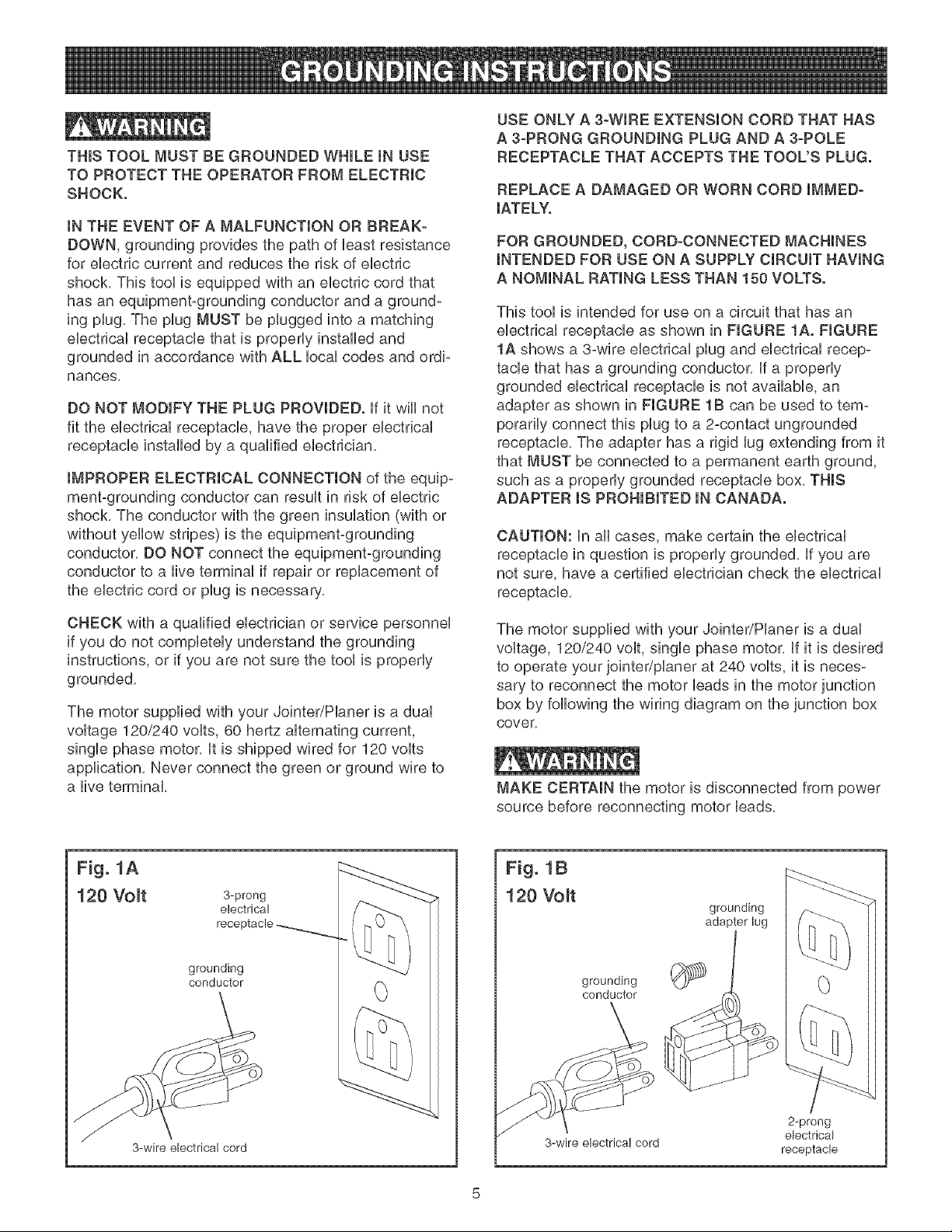
This tool is intended for use on a circuit that has an
electrical receptacle as shown in FIGURE 1A. FIGURE
1A shows a 3-wire electrical plug and electrical recep-
tacle that has a grounding conductor, if a properly
grounded electrical receptacle is not available, an
adapter as shown in FIGURE 1B can be used to tem-
porarily connect this plug to a 2-contact ungrounded
receptacle, The adapter has a rigid lug extending from it
that MUST be connected to a permanent earth ground,
such as a properly grounded receptacle box, THIS
ADAPTER IS PROHIBITED IN CANADA.
CAUTION: in all cases, make certain the electrical
receptacle in question is properly grounded, if you are
not sure, have a certified electrician check the electrical
receptacle,
CHECK with a qualified electrician or service personnel
if you do not completely understand the grounding
instructions, or if you are not sure the tool is properly
grounded,
The motor supplied with your Jointer/Planer is a dual
voltage 120/240 volts, 60 hertz alternating current,
single phase motor, it is shipped wired for 120 volts
application, Never connect the green or ground wire to
a live terminal,
Fig. 1A
120 Volt 3-prong
electrical
receptacle
grounding
conductor
The motor supplied with your Jointer/Planer is a dual
voltage, 120/240 volt, single phase motor, if it is desired
to operate your jointer/planer at 240 volts, it is neces-
sary to reconnect the motor leads in the motor junction
box by following the wiring diagram on the junction box
cover,
MAKE CERTAIN the motor is disconnected from power
source before reconnecting motor leads,
Fig. 1B
120 Voff
grounding
adapter lug
grounding
conductor
0
3-wire electrical cord
3-wire electrical cord
2-prong
electrical
receptacle

it is aUsonecessary to repUacethe 120 voUtpUug,sup-
plied with the motor, with a UL/CSA Listed pUugsuitabb
for 240 voUtsand rated current of the jointer/pUaner,
Contact a bcaU qualified eUectdcian for proper proce-
dures to install the pUug,The jointer/pUaner must compUy
with aHbcaUand nationaU eUectdcaUcodes after the
240 voUtpUugis installed,
The jointer/planer with a 240 volt plug should only be
connected to an outlet having the same configuration
as the plug shown in FmGURE2, No adapter is available
or should be used with the 240 volt plug,
Fig. 2
240 Volt
current carMng
prongs
grounding blade is
longest of the 3 blades
grounded outlet box
6)
3,
KEEP cutterhead knives sharp and free of all rust
and pitch,
4,
BEFORE starting machine, check cutterhead guard
to make sure it is not damaged and operates freely,
5,
ALWAYS make sure exposed cutterhead behind
the fence is guarded, especially when jointing near
the edge,
6,
NEVER perform jointing or planing operations with
the cutterhead guard removed,
7,
MAKE CERTAIN the infeed and outfeed tables are
tightened before starting the machine,
8,
NEVER start the jointer with the workpiece contact-
ing the cutterhead,
9,
ALWAYS hold the workpiece firmly against the
tables and fence,
10,
NEVER perform any operations "FREE-HAND"
which means using your hands to support or guide
the workpiece, ALWAYS use the fence to position
and guide the work,
MAKE CERTAIN the receptacle in question is properly
grounded, if you are not sure have a qualified electric-
ian check the receptacle,
This Jointer/Planer is for indoor use only, Do not
expose to rain or use in damp locations,
SPECIFIC SAFETY iNSTRUCTiONS
FOR JOINTER/PLANER
The operation of any Jointer/Planer can result in debris
being thrown into your eyes, which can result in severe
eye damage, ALWAYS wear Safety Goggles (that
comply with ANSi standard Z87,1 ) when operating the
Jointer/Planer, Safety Goggles are available at Sears
Retail Stores, Keep your thumbs and fingers away from
the cutterhead,
1, WARNING: Do not operate the Jointer/Planer until
it is completely assembled and installed according
to the instructions,
2, IF YOU ARE NOT thoroughly familiar with the oper-
ation of Jointers/Pianers, obtain advice from your
supervisor, instructor or other qualified person,
11,
AVOID awkward operations and hand positions
where a sudden slip could cause your hand to
move into the cutterhead,
12,
ALWAYS use hold-down/push blocks for jointing
material less than 3 inches in height or planing
material thinner than 3 inches,
13,
DO NOT perform jointing operations on material
shorter than 10 inches, narrower than 3/4 inch or
less than 1/2 inch thick,
14,
DO NOT perform planing operations on material
shorter than 10 inches, narrower than 3/4 inch or
less than 1/2 inch thick,
15,
NEVER make jointing or planing cuts deeper than
1/8 inch, On cuts more than 1-1/2 inches wide,
adjust depth of cut to 1/16 inch or less to avoid
overloading machine and to minimize chance of
kickback (work thrown back toward you),
16,
MAINTAIN the proper height between the outfeed
table surface and the cutting circle of the knives,
17,
SUPPORT the workpiece adequately at all times
during operation; maintain control of the work at all
times,
18,
DO NOT back the workpiece over the cutterhead
toward the infeed table,
19,DONOTattemptto performanabnormalorlittle-
usedoperationwithoutstudyandtheuseofade-
quateholddown/pushblocks,jigs,fixtures,stops,
pushblocks,etc,
20,SHUTOFFpowerbeforeadjustingjointer,
21,DISCONNECTJointer/Hanerfrompowersource
beforeservicinganddeanthemachinebefore
havingit,
22,MAKESUREtheworkareaiscleanbeforehaving
themachine,
permanentrespiratoryorotherinjury,including
silicosis(aseriouslungdisease),cancer,and
death.Avoidbreathingthedust,andavoidpro-
longedcontactwithdust.Allowingdustto getinto
yourmouthoreyes,orlayonyourskinmaypro-
moteabsorptionofharmfulmaterial.Alwaysuse
properlyfittingNIOSH/OSHAapprovedrespiratory
protectionappropriateforthedustexposure,and
washexposedareawithsoapandwater.
26.
ADDITIONALINFORMATIONregardingthesafe
andproperoperationofthisproductisavailable
from:
23,SHOULDanypartofyourjointerbemissing,dam-
aged,orfailinanyway,oranyebctdcalcompo-
nentsfailtoperformproperly,shutoffswitchand
removeplugfrompowersupplyoutbt,Replace
missing,damagedorfaibdpartsbeforeresuming
operation,
24.THEUSEofattachmentsandaccessoriesnot
recommendedmayresultintheriskofinjuries.
25,USEofthistoolcangenerateanddisbursedustor
otherairborneparticles,includingwooddust,crys-
tallinesilicadustandasbestosdust,Directparticles
awayfromfaceandbody,Alwaysoperatetoolin
wellventilatedareaandprovideforproperdust
removal,Usedustcollectionsystemwhereverpos-
sibb,Exposuretothedustmaycauseseriousand
PowerToolinstitute
1300SummerAvenue
Cleveland,OH44115-2851
www.powertoolinstitute.org
NationalSafetyCouncil
1121SpringLakeDrive
Itasca,IL60143-3201
AmericanNationalStandardsinstitute
25West43rdStreet,4thFloor
NewYork,NY10036
www.ansi.org
ANSi01.1SafetyRequirementsfor
WoodworkingMachinesandthe
U.S.DepartmentofLaborRegulations
www.osha.gov
27,SAVETHESEINSTRUCTIONS,Refertothem
oftenandusethemtoinstructothers,
AVAILABLE ACCESSORIES
Visit your Sears Hardware Department or see the
Sears Power and Hand Tool Catalog for the following
accessories.
ITEM
Replacement Push Blocks
Sears may recommend other accessories not listed in
this manual.
See your nearest Sears Hardware Department or Sears
Power and Hand Tool Catalog for other accessories.
Do not use any accessory unless you have completely
read the Owner's Manual for that accessory.
Use only accessories recommended by Sears for this
Jointer/Planer. Using other accessories may cause
serious injury and cause damage to the Jointer/Planer.
UNPACKUNG AND CHECKUNG CONTENTS
The Jointer/Haner is a heavy machine, two peopb are
required to unpack and lift it, This machine will require
some amount of assembly, You will need for assembly
a #2 Phillips screwdriver, 8mm, lOmm, 14mm, 16mm,
17mm and 19mm open end wrench (not included), Hex
wrenches 2,5mm, 3mm, 4mm and 6mm are provided,
1, Remove all parts from the carton and lay them on a
clean work surface,
2, Two or more people are required to lift the
Jointer/Planer out of the carton,
3,
Remove all protective materials and coatings from
the parts, The protective coatings can be removed
by spraying WD-40 on a part and wiping it off with a
soft cloth, This may need to be redone several
times before all of the protective coatings are
removed completely,
CAUTION: DO NOT use acetone, gasoline or
lacquer thinner to remove any protective coatings,
4,
After cleaning, apply a good quality automotive wax
to any unpainted surfaces, Make sure to buff out
the wax before assembly,
5,
Compare the parts to figures 2-1,2°2, and 2-3,
Verify that all items are accounted for before dis-
carding the shipping carton, if there are any missing
parts, call Customer Helpline 1-800-897°7709,
Please have your part number ready, Part numbers
can be found in the Parts List section of your
instruction Manual,
To avoid injury, DO NOT turn on the Jointer/Planer until
all parts have been assembled correctly, if any parts
are broken or missing DO NOT use until the parts have
been obtained and assembled,
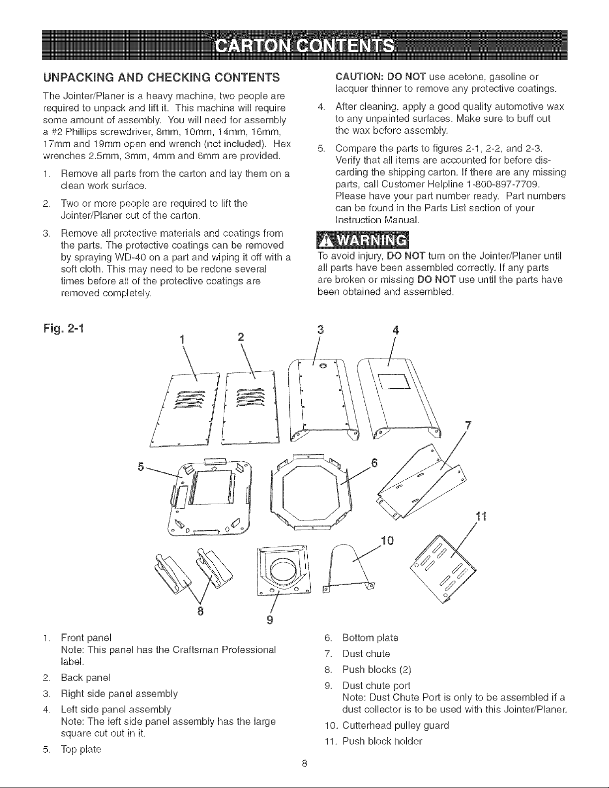
Fig. 2-1
2
3 4
11
10
1, Front panel
Note: This panel has the Craftsman Professional
label,
2, Back panel
3, Right side panel assembly
4, Left side panel assembly
Note: The left side panel assembly has the large
square cut out in it,
5, Top plate
9
6, Bottom plate
7, Dust chute
8, Push blocks (2)
9, Dust chute port
Note: Dust Chute Port is only to be assembled if a
dust collector is to be used with this Jointer/Planer,
10, Cutterhead pulley guard
11, Push block holder
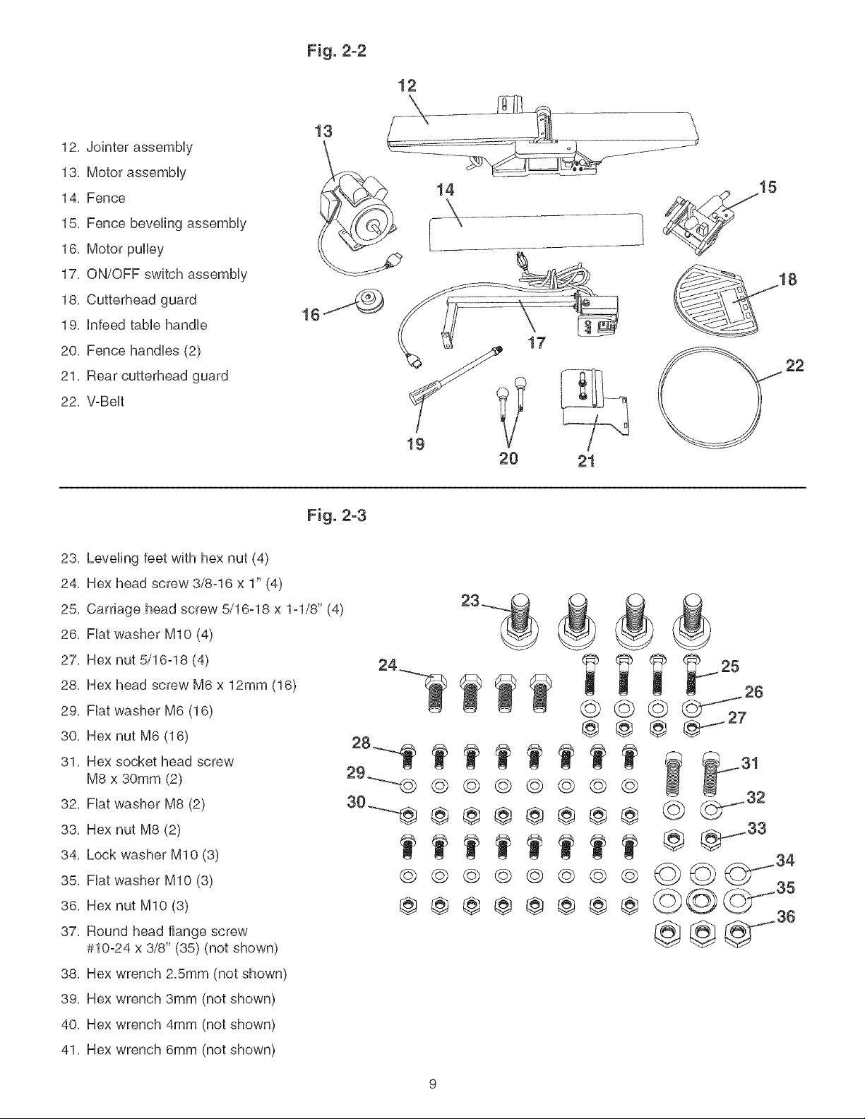
12,Jointerassembly
13,Motorassembly
14,Fence
15,Fencebevelingassembly
16,Motorpulley
17,ON/OFFswitchassembly
18,Cutterheadguard
19,Infeedtablehandle
20,Fencehandles(2)
21,Rearcutterheadguard
22,V-Belt
Fig. 2-2
12
18
17
22
20 21
Fig. 2-3
23, Leveling feet with hex nut (4)
24, Hex head screw 3/8-16 x 1" (4)
25, Carriage head screw 5/16o18 x 1ol/8" (4)
26, Fiat washer MIO (4)
27, Hex nut 5/16°18 (4)
28, Hex head screw M6 x 12mm (16)
29, Fiat washer M6 (16)
30, Hex nut M6 (16)
31, Hex socket head screw
M8 x 30mm (2)
32, Fiat washer M8 (2)
33, Hex nut M8 (2)
34, Lock washer MIO (3)
35, Fiat washer MIO (3)
36, Hex nut MIO (3)
37, Round head flange screw
#10o24 x 3/8" (35) (not shown)
29----m@ @
© ©
@®
@@@@
@@@@
@@@@
@@@@
@@@
@@@
@ @
@ @ (_ 32
36
@@
38, Hex wrench 2,Smm (not shown)
39, Hex wrench 3mm (not shown)
40, Hex wrench 4mm (not shown)
41, Hex wrench 6mm (not shown)

Fig. 3-1
_6
5_
3
2
7
10
1, Outfeed TaMe
2, Fence
3, Fence Cam HockhandHe
4, Fence handHe
5, ThermaH reset button
6, ON/OFF switch
7, Cutterhead guard
8, Hnfeed tame
9, Hnfeed tame height adjustment handHe
12
13
10, Depth-of-Cut scaHe
11, Push Mocks
12, Push Mock hoHder
13, EncHosed stand
14, Leveling feet
15, Dust Chute Port
Note: Dust Chute Port is onHyto be assembHed if a
dust coHHectoris to be used with this Jointer/PHaner
16, Outfeed tame height adjustment handHe
10
TO AVOmDSERmOUSmNJURYAND DAMAGE TO THE
JOmNTER/PLANEFt:
1, DO NOT assemble the Jointer/Planer until you are
sure the tool mSNOT plugged in,
2, DO NOT assemble the Jointer/Planer until you are
sure the power switch is in the "OFF" position,
3, DO NOT assemble the Jointer/Planer until you have
read and understood this entire instruction Manual,
4, DO NOT assemble Jointer/Planer if any parts are
missing or damaged,
C
13"
A
Fig. 4-2 I
C
G
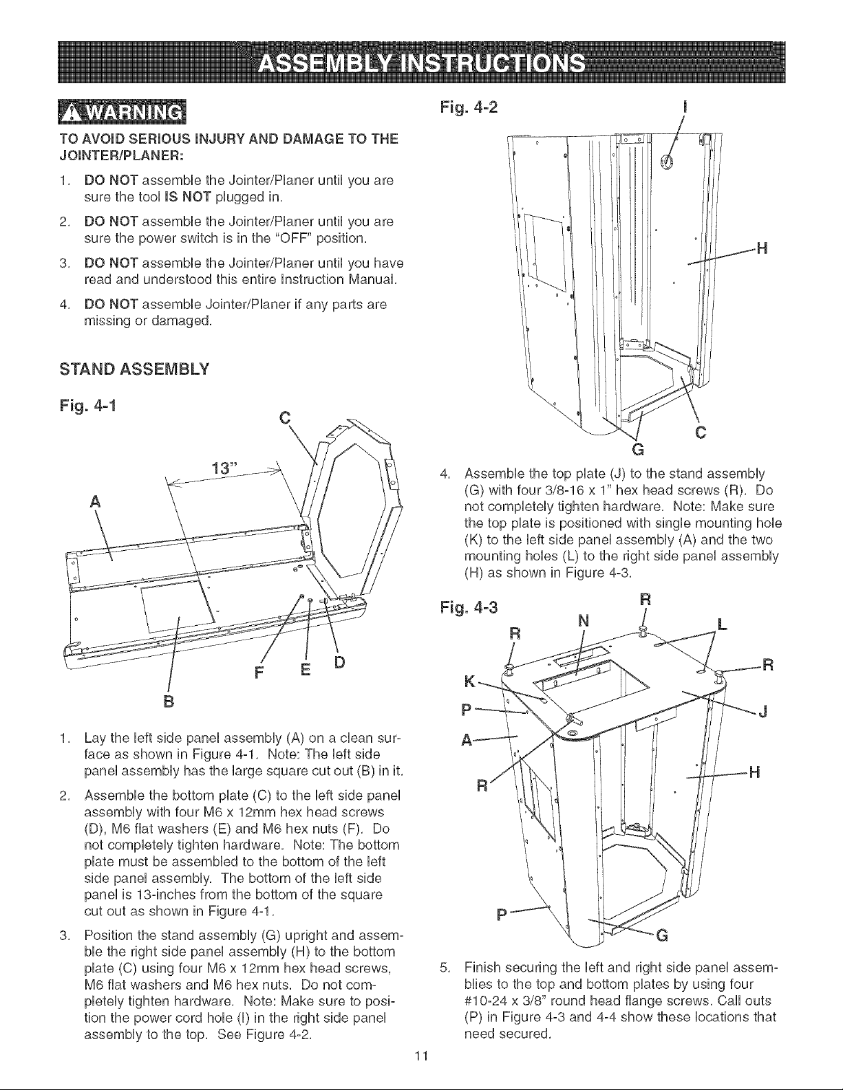
4,
Assemble the top plate (J) to the stand assembly
(G) with four 3/8-16 x 1" hex head screws (R), Do
not completely tighten hardware, Note: Make sure
the top plate is positioned with single mounting hob
(K) to the left side panel assembly (A) and the two
mounting hobs (L) to the right side panel assembly
(H) as shown in Figure 4-3,
B
1, Lay the left side panel assembly (A) on a clean sur-
face as shown in Figure 4-1, Note: The left side
panel assembly has the large square cut out (B) in it,
2, Assemble the bottom plate (C) to the left side panel
assembly with four M6 x 12mm hex head screws
(D), M6 fiat washers (E) and M6 hex nuts (F), Do
not completely tighten hardware, Note: The bottom
plate must be assembled to the bottom of the left
side panel assembly, The bottom of the left side
panel is 13-inches from the bottom of the square
cut out as shown in Figure 4-1,
3, Position the stand assembly (G) upright and assem-
ble the right side panel assembly (H) to the bottom
plate (C) using four M6 x 12mm hex head screws,
M6 fiat washers and M6 hex nuts, Do not com-
pletely tighten hardware, Note: Make sure to posi-
tion the power cord hob (I) in the right side panel
assembly to the top, See Figure 4-2,
11
N
5,
Finish securing the left and right side panel assem-
bibs to the top and bottom plates by using four
#10-24 x 3/8" round head flange screws, Call outs
(P) in Figure 4-3 and 4-4 show these locations that
need secured,
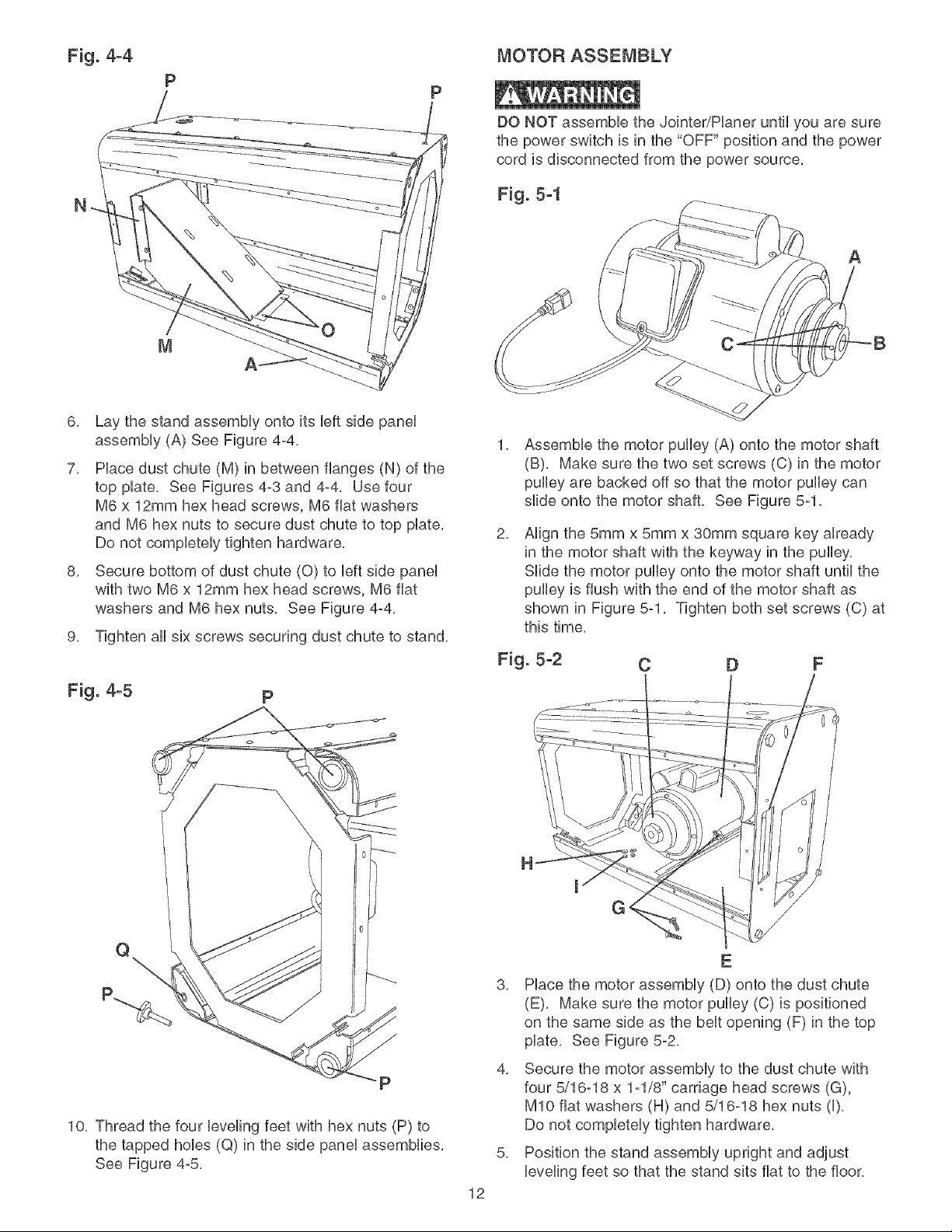
Fig. 4-4 MOTOR ASSEMBLY
P
DO NOT assemMe the Jointer/Haner until you are sure
the power switch is in the "OFF" position and the power
cord is disconnected from the power source,
N
6, Lay the stand assemMy onto its Ueftside paneU
assemMy (A) See Figure 4-4,
7, Hace dust chute (M) in between flanges (N) of the
top pUate, See Figures 4-3 and 4-4, Use four
M6 x 12mm hex head screws, M6 fiat washers
and M6 hex nuts to secure dust chute to top pUate,
Do not compUeteUytighten hardware,
8, Secure bottom of dust chute (0) to Ueftside paneU
with two M6 x 12mm hex head screws, M6 fiat
washers and M6 hex nuts, See Figure 4-4,
1,
Assemble the motor pulley (A) onto the motor shaft
(B), Make sure the two set screws (C) in the motor
pulley are backed off so that the motor pulley can
slide onto the motor shaft, See Figure 5-1,
2,
AHgn the 5mm x 5mm x 30mm square key aUready
in the motor shaft with the keyway in the pufley,
SHde the motor pufley onto the motor shaft until the
pufley is flush with the end of the motor shaft as
shown in Figure 5-1, Tighten both set screws (C) at
this time,
9, Tighten aft six screws securing dust chute to stand,
Fig. 5-2 C D
A
Fig. 4-5 p
X\
10, Thread the four leveling feet with hex nuts (P) to
the tapped holes (Q) in the side panel assemblies,
See Figure 4-5,
12
H
E
3,
Place the motor assembly (D) onto the dust chute
(E), Make sure the motor pulley (C) is positioned
on the same side as the belt opening (F) in the top
plate, See Figure 5-2,
4,
Secure the motor assembly to the dust chute with
four 5/16-18 x 1-1/8" carriage head screws (G),
MIO flat washers (H) and 5/16-18 hex nuts (I),
Do not completely tighten hardware,
5,
Position the stand assembly upright and adjust
leveling feet so that the stand sits flat to the floor,
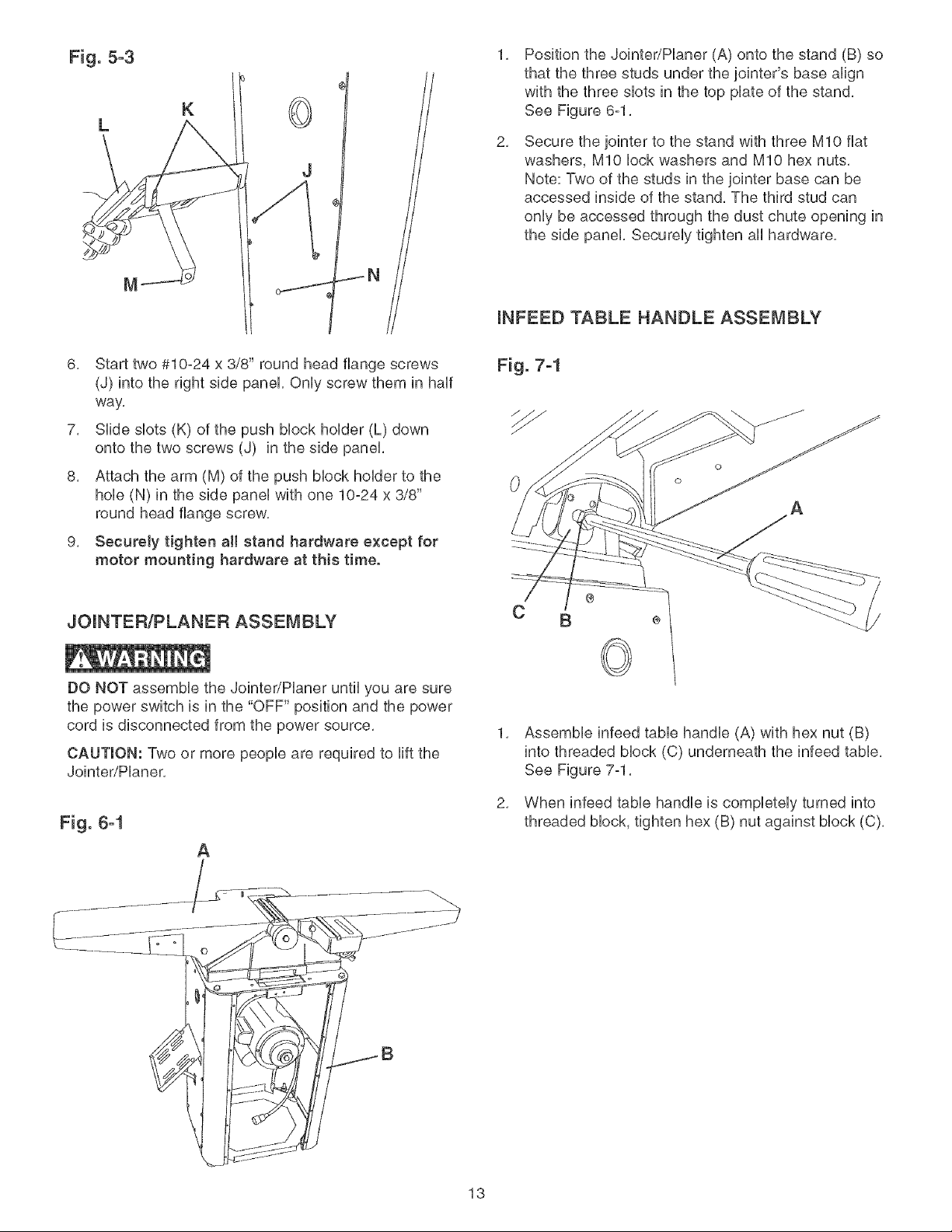
Fig. 5-3
L
1,
Position the Jointer/Haner (A) onto the stand (B) so
that the three studs under the jointer's base a(ign
with the three sbts in the top plate of the stand,
K
See Figure 6-1,
2,
Secure the jointer to the stand with three MIO fiat
washers, MIO bck washers and MIO hex nuts,
Note: Two of the studs in the jointer base can be
accessed inside of the stand, The third stud can
only be accessed through the dust chute opening in
the side panel Securely tighten aU hardware,
(NFEED TABLE HANDLE ASSEMBLY
6, Start two #10-24 x 3/8" round head flange screws
(J) into the right side panel Only screw them in haft
way,
7, SHde sbts (K) of the push Mock holder (L) down
onto the two screws (J) in the side panel
8, Attach the arm (M) of the push Mock holder to the
hob (N) in the side pane( with one 10-24 x 3/8"
round head flange screw,
9, Securely tighten a)( stand hardware except for
motor mounting hardware at this time.
JO(NTER/PLANER ASSEMBLY
DO NOT assemble the Jointer/Haner until you are sure
the power switch is in the "OFF" position and the power
cord is disconnected from the power source,
CAUTION: Two or more people are required to lift the
Jointer/Haner,
Fig. 6-1
A
Fig. 7-1
@
C B ÷
©
1,
Assemble infeed table handle (A) with hex nut (B)
into threaded block (C) underneath the infeed table,
See Figure 7-1,
2,
When infeed table handle is completely turned into
threaded block, tighten hex (B) nut against block (C),
13
BELT ASSEMBLY GUARD AND SWITCH ASSEMBLY
DO NOT assembb the Jointer/Haner until you are sure
the power switch is in the "OFF" position and the power
cord is disconnected from the power source,
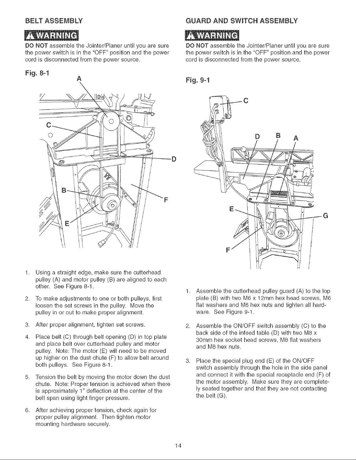
Fig. 8-1
A
O
DO NOT assembb the Jointer/Haner until you are sure
the power switch is in the "OFF" position and the power
cord is disconnected from the power source,
Fig. 9-1
D B A
Using a straight edge, make sure the cutterhead
pulby (A) and motor pulby (B) are aligned to each
other, See Figure 8-1,
2,
To make adjustments to one or both pulbys, first
loosen the set screws in the pulby, Move the
pulby in or out to make proper alignment,
8,
After proper alignment, tighten set screws,
4,
Hace belt (C) through belt opening (D) in top plate
and place belt over cutterhead pulby and motor
pulby, Note: The motor (E) will need to be moved
up higher on the dust chute (F) to allow belt around
both pulleys, See Figure 8-1,
8,
Tension the belt by moving the motor down the dust
chute, Note: Proper tension is achieved when there
is approximately 1" deflection at the center of the
belt span using light finger pressure,
1,
Assemble the cutterhead pulley guard (A) to the top
plate (B) with two M6 x 12mm hex head screws, M6
fiat washers and M6 hex nuts and tighten all hard°
ware, See Figure 9-1,
2,
Assemble the ON/OFF switch assembly (C) to the
back side of the infeed table (D) with two M8 x
30mm hex socket head screws, M8 fiat washers
and M8 hex nuts,
8,
Place the special plug end (E) of the ON/OFF
switch assembly through the hob in the side panel
and connect it with the special receptacle end (F) of
the motor assembly, Make sure they are complete-
ly seated together and that they are not contacting
the belt (G),
G
6,
After achieving proper tension, check again for
proper pulley alignment, Then tighten motor
mounting hardware securely,
14
FENCE ASSEMBLY
DO NOT assemble the Jointer/Haner until you are sure
the power switch is in the "OFF" position and the power
cord is disconnected from the power source,
\
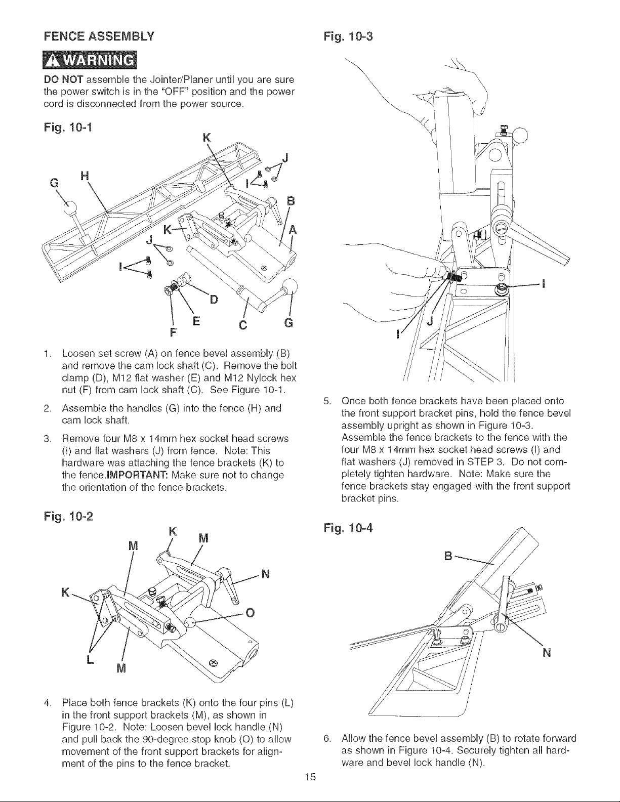
Fig. 10-1
K
G
H
E C G
F
Loosen set screw (A) on fence bevel assembly (B)
and remove the cam lock shaft (C), Remove the bolt
damp (D), M12 fiat washer (E) and M12 Nylock hex
nut (F) from cam lock shaft (C), See Figure 10-1,
2,
Assemble the handles (G) into the fence (H) and
cam lock shaft,
3,
Remove four M8 x 14mm hex socket head screws
(I) and fiat washers (J) from fence, Note: This
hardware was attaching the fence brackets (K) to
the fence,IMPORTANT: Make sure not to change
the orientation of the fence brackets,
J
B
5,
Once both fence brackets have been placed onto
the front support bracket pins, hold the fence bevel
assembly upright as shown in Figure 10-3,
Assemble the fence brackets to the fence with the
four M8 x 14mm hex socket head screws (I) and
fiat washers (J) removed in STEP 3, Do not com-
pletely tighten hardware, Note: Make sure the
fence brackets stay engaged with the front support
bracket pins,
Fig. 10-2
K
4,
Hace both fence brackets (K) onto the four pins (L)
in the front support brackets (M), as shown in
Figure 10-2, Note: Loosen bevel lock handle (N)
and pull back the 90-degree stop knob (0) to allow
movement of the front support brackets for align-
ment of the pins to the fence bracket,
Fig. 10-4
N
N
6,
Allow the fence bevel assembly (B) to rotate forward
as shown in Figure 10-4, Securely tighten all hard-
ware and bevel lock handle (N),
15
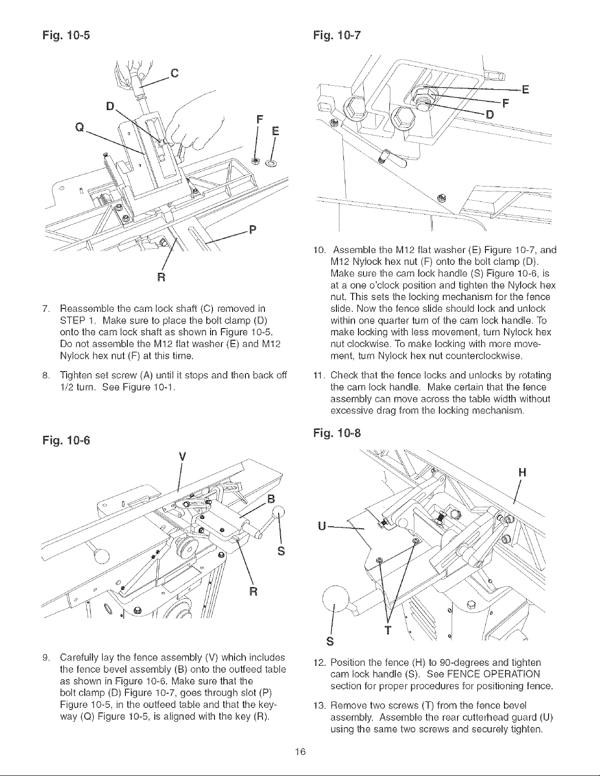
Fig. 10-5 Fig. 10-7
10,
Assemble the M12 fiat washer (E) Figure 10-7, and
M12 Nylock hex nut (F) onto the bolt clamp (D),
Make sure the cam lock handle (S) Figure 10-6, is
at a one o'clock position and tighten the Nyloek hex
nut, This sets the locking mechanism for the fence
7,
Reassembb the cam lock shaft (C) removed in
STEP 1, Make sure to place the bolt clamp (D)
onto the cam lock shaft as shown in Figure 10-5,
Do not assembb the M12 fiat washer (E) and M12
Nylock hex nut (F) at this time,
slide, Now the fence slide should lock and unlock
within one quarter turn of the cam lock handle, To
make locking with less movement, turn Nylock hex
nut clockwise, To make locking with more move-
ment, turn Nylock hex nut counterclockwise,
E
5,
Tighten set screw (A) until it stops and then back off
1/2 turn, See Figure 10-1,
Fig. 10-6
9,
Carefully lay the fence assembly (V) which includes
the fence bevel assembly (B) onto the outfeed table
as shown in Figure 10-6, Make sure that the
bolt clamp (D) Figure 10-7, goes through slot (P)
Figure 10-5, in the outfeed table and that the key-
way (Q) Figure 10-5, is aligned with the key (R),
11,
Check that the fence locks and unlocks by rotating
the cam lock handle, Make certain that the fence
assembly can move across the table width without
excessive drag from the locking mechanism,
Fig. 10-8
H
I
T
S
12, Position the fence (H) to 90-degrees and tighten
cam lock handle (S). See FENCE OPERATION
section for proper procedures for positioning fence,
13, Remove two screws (T) from the fence bevel
assembly, Assemble the rear cutterhead guard (U)
using the same two screws and securely tighten,
16
CUTTERHEAD GUARD ASSEMBLY FRONT AND BACK PANEL ASSEMBLY
DO NOT assembie the Jointer/Pianer until you are sure
the power switch is in the "OFF" position and the power
cord is disconnected from the power source,
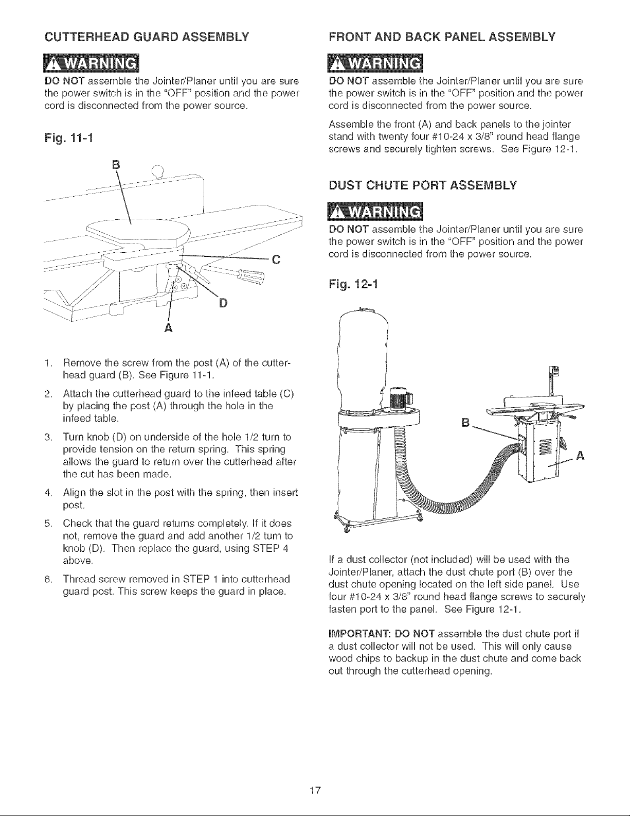
Fig. 11-1
B
C
A
1, Remove the screw from the post (A) of the cutter-
head guard (B), See Figure 11-1,
DO NOT assembie the Jointer/Pianer until you are sure
the power switch is in the "OFF" position and the power
cord is disconnected from the power source,
Assembie the front (A) and back paneis to the jointer
stand with twenty four #10-24 x 3/8" round head flange
screws and secureiy tighten screws, See Figure 12-1,
DUST CHUTE PORT ASSEMBLY
DO NOT assembie the Jointer/Pianer until you are sure
the power switch is in the "OFF" position and the power
cord is disconnected from the power source,
Fig. 12-1
2, Attach the cutterhead guard to the infeed tame (C)
by piacing the post (A) through the hob in the
infeed tame,
3,
Turn knob (D) on underside of the hob 1/2 turn to
provide tension on the return spring, This spring
allows the guard to return over the cutterhead after
the cut has been made,
4, Align the slot in the post with the spring, then insert
post,
5, Check that the guard returns completely, if it does
not, remove the guard and add another 1/2 turn to
knob (D), Then replace the guard, using STEP 4
above,
6, Thread screw removed in STEP 1 into cutterhead
guard post, This screw keeps the guard in place,
B
if a dust collector (not included) wiii be used with the
Jointer/Planer, attach the dust chute port (B) over the
dust chute opening located on the left side panel, Use
four #10-24 x 3/8" round head flange screws to securely
fasten port to the panel, See Figure 12-1,
IMPORTANT: DO NOT assemble the dust chute port if
a dust collector wiii not be used, This wiii only cause
wood chips to backup in the dust chute and come back
out through the cutterhead opening,
17
CAUTION
• AseparateeUectdcaUcircuitshouUdbeusedforyour
Jointer/Haner.TheJointer/Hanercomespre-wiredfor
120-voUtuse.ThecircuitshouUdnotbeUessthan#14
AWGwireandshouUdbeprotectedwitha15-amp
timeUagfuse.
HaveaquaUifiedeUectdcianrepairorrepUacedam-
agedorworncordimmediateUy.
BeforeconnectingthemotortothepowerHne,make
certaintheswitchisinthe"OFF"positionandbesure
thattheeUectriccurrentisofthesamecharacteristics
asthemotornamepUate.AHHneconnectionsshouUd
makegoodcontact.
RunningonUowvoUtageorUongextensioncordswHU
damagethemotor.
STARTING AND STOPPING
,, DO NOT expose the Jointer/Haner to rain or operate
it in damp locations,
2. To turn the Jointer/Haner on, press the green "ON"
button (B) in one-half inch. Note: There is a safety
feature on the switch to insure that the switch must
be completely pressed before the motor will start.
3. To turn the Jointer/Haner off, press the large red
"OFF" paddle (C) or lift the paddle and press direct°
ly on the red "OFF" button (D). See Figure 13-1
and 13-2.
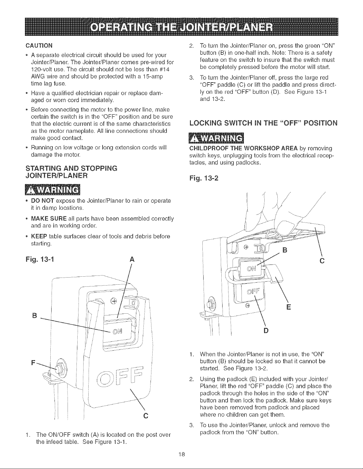
LOCKING SWITCH IN THE "OFF" PosmoN
CHILDPROOF THE WORKSHOP AREA by removing
switch keys, unplugging tools from the electrical recep-
tacles, and using padlocks.
Fig. 13-2
MAKE SURE all parts have been assembled correctly
and are in working order,
,, KEEP table surfaces clear of tools and debris before
starting,
Fig. 13-1 A
B
r
C
1. The ON/OFF switch (A) is located on the post over
the infeed table. See Figure 13-1.
C
E
D
1. When the Jointer/Planer is not in use, the "ON"
button (B) should be locked so that it cannot be
started. See Figure 13o2.
2. Using the padlock (E) included with your Jointeri
Planer, lift the red "OFF" paddle (C) and place the
padlock through the holes in the side of the "ON"
button and then lock the padlock. Make sure keys
have been removed from padlock and placed
where no children can get them.
3. To use the Jointer/Planer, unlock and remove the
padlock from the "ON" button.
18
 Loading...