

Page 1
Owner’s Manual
CRRFTSMRN
PIOFESSIOHAL
1-1/2 Horsepower (continyous duty)
2.1 Horsepower (maximum developed)
1200 C.F.M.
3450 R.P.M. (no load R.P.M.)
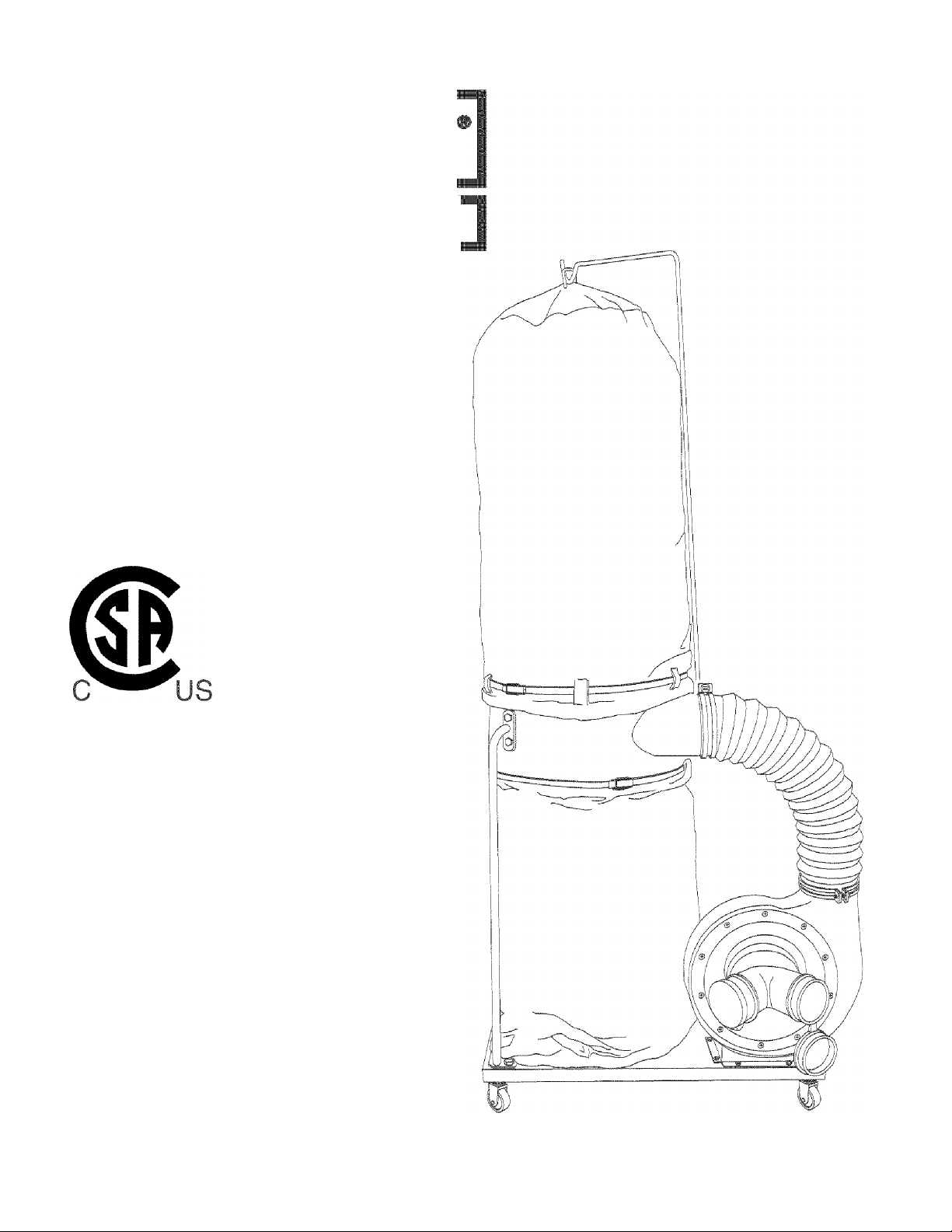
DUST COLLECTOR
Model No.
152.213371
CAUTION:
FOR YOUR OWN SAFETY; Read
and foilow all of the Safety and
Operating Instructions before
Operating this Dust Collector.
Customer Helpline
1-800-897-7709
Please have your Model No.
and Serial No. available.
Sears, Roebuck and Co., Hoffman Estates, IL 60179 U.S.A.
Part No. OR93765
Espanol pg. 25
Page 2

SECTION PAGE
Warranty..................................................................................... 2
Product Specifications ......................................................................... 2
Safety Instructions ............................................................................ 3
Grounding Instructions......................................................................... 5
Specific Safety Instructions for Dust Collectors .................................................... 6
Accessories and Attachments................................................................... 7
Carton Contents .............................................................................. 8
Know Your Dust Collector ..................................................................... 10
Assembly Instructions ........................................................................ 11
Operating the Dust Collector................................................................... 15
Dust Collector in the Shop..................................................................... 17
Maintenance................................................................................. 20
Troubleshooting Guide........................................................................ 20
Parts List ................................................................................... 21
Service Information........................................................................... 48
WARRANT
£
ONE-YEAR FULL WARRANTY ON CRAFTSMAN PROFESSIONAL TOOL
If this Craftsman tool fails due to a defect in material or workmanship within one year from the date of purchase,
CALL 1 -800-4-MY-HOME® TO ARRANGE FOR FREE REPAIR.
This warranty applies only while this tool is in the United States.
This warranty gives you specific legal rights, and you may also have other rights, which vary, from state to state.
Sears, Roebuck and Co., Dept. 817WA, Hoffman Estates, IL 60179 06/05
PRODUCT SPECIFICATION
Induction Motor
Continuous duty HP
Maximum developed HP
Amps
Volts
Hertz
RPM
Standard Bag Top
Standard Bag Bottom
Collection Hose
Maximum C. F. M.
Maximum static pressure
in inches of water
1-1/2
2.1
12/6
120/240
60
3450 R.P.M.
(no load R.P.M.)
30 micron
30 micron
4-inch Flexible Hose
1200
12
Awarning
To avoid electrical shock to yourself and damage to the
Dust Collector, use proper circuit protection. Do not
expose to rain, or use in a damp environment.
The Dust Collector is factory wired for 120V, 60 Hz,
operation. Connect to a 120V, 15 amp branch circuit
and use a 15 amp time delay fuse or circuit breaker.
The electrical circuit cannot have any wire size less
than #14. To avoid shock or fire, replace power cord
immediately if it is damaged in any way.
Filter Bag capacity
Collection Bag capacity
6 cubic feet
6 cubic feet
Page 3

GENERAL SAFETY INSTRUCTIONS
Operating a Dust Collector can be dangerous if safety
and common sense are ignored. The operator must be
familiar with the operation of the tool. Read this manual
to understand this Dust Collector. DO NOT operate this
Dust Collector if you do not fully understand the limita
tions of this tool. DO NOT modify this Dust Collector in
any way. REMEMBER: Your personal safety is your
responsibility.
BEFORE USING THE DUST COLLECTOR
9. ALWAYS WEAR EYE PROTECTION. Any power
tool can throw debris into the eyes during opera
tions, which could cause severe and permanent
eye damage. Everyday eyeglasses are NOT safety
glasses. ALWAYS Wear Safety Goggles (that
comply with ANSI standard Z87.1) when operating
power tools. Safety Goggles are available at Sears
Retail Stores.
ikWARNING
To avoid serious injury and damage to the tool, read
and follow all of the Safety and Operating Instructions
before operating the Dust Collector.
1. READ the entire Owner's Manual. LEARN how to
use the tool for its intended applications.
2. GROUND ALL TOOLS. If the tool is supplied with a
3-prong plug, it must be plugged into a 3-contact
electrical receptacle. The 3rd prong is used to
ground the tool and provide protection against
accidental electric shock. DO NOT remove the 3rd
prong. See Grounding Instructions.
3. AVOID A DANGEROUS WORKING ENVIRON
MENT. DO NOT use electrical tools in a damp
environment or expose them to rain.
4. DO NOT use electrical tools in the presence of
flammable liquids or gasses.
5. ALWAYS keep the work area clean, well lit, and
organized. DO NOT work in an environment with
floor surfaces that are slippery from debris, grease,
and wax.
6. KEEP VISITORS AND CHILDREN AWAY. DO NOT
permit people to be in the immediate work area,
especially when the electrical tool is operating.
7. DO NOT FORCE THE TOOL to perform an opera
tion for which it was not designed. It will do a safer
and higher quality job by only performing operations
for which the tool was intended.
8. WEAR PROPER CLOTHING. DO NOT wear loose
clothing, gloves, neckties, or jewelry. These items
can get caught in the machine during operations
and pull the operator into the moving parts. The
user must wear a protective cover on their hair, if
the hair is long, to prevent it from contacting any
moving parts.
10. ALWAYS WEAR HEARING PROTECTION. Plain
cotton is not an acceptable protective device.
Hearing equipment should comply with ANSI S3.19
Standards.
11. ALWAYS UNPLUG THE TOOL FROM THE ELEC
TRICAL RECEPTACLE when making adjustments,
changing parts or performing any maintenance.
12. KEEP PROTECTIVE GUARDS IN PLACE AND IN
WORKING ORDER.
13. AVOID ACCIDENTAL STARTING. Make sure that
the power switch is in the "OFF" position before
plugging in the power cord to the electrical
receptacle.
14. REMOVE ALL MAINTENANCE TOOLS from the
immediate area prior to turning the tool “ON".
15. USE ONLY RECOMMENDED ACCESSORIES.
Use of incorrect or improper accessories could
cause serious injury to the operator and cause
damage to the tool. If in doubt, check the instruction
manual that comes with that particular accessory.
16. NEVER LEAVE A RUNNING TOOL UNATTENDED.
Turn the power switch to the "OFF" position. DO
NOT leave the tool until it has come to a complete
stop.
17. DO NOT STAND ON A TOOL. Serious injury could
result if the tool tips over or you accidentally contact
the tool.
18. DO NOT store anything above or near the tool where
anyone might try to stand on the tool to reach it.
19. MAINTAIN YOUR BALANCE. DO NOT extend your
self over the tool. Wear oil resistant rubber-soled
shoes. Keep floor clear of debris, grease, and wax.
20. MAINTAIN TOOLS WITH CARE. Always keep tools
clean and in good working order. Keep all blades
and tool bits sharp.
Page 4

21. EACH AND EVERY TIME, CHECK FOR DAM
AGED PARTS PRIOR TO USING THE TOOL.
Carefully check all guards to see that they operate
properly, are not damaged, and perform their
intended functions. Check for alignment, binding or
breaking of moving parts. A guard or other part that
is damaged should be immediately repaired or
replaced.
22. CHILDPROOF THE WORKSHOP AREA by remov
ing switch keys, unplugging tools from the electrical
receptacles, and using padlocks.
23. DO NOT OPERATE TOOL IF UNDER THE INFLU
ENCE OF DRUGS OR ALCOHOL.
24. SECURE ALL WORK. When it is possible, use
clamps or jigs to secure the work-piece. This is
safer than attempting to hold the work-piece with
your hands.
25. STAY ALERT, WATCH WHAT YOU ARE DOING,
AND USE COMMON SENSE WHEN OPERATING
A POWER TOOL. DO NOT USE A TOOL WHILE
TIRED OR UNDER THE INFLUENCE OF DRUGS,
ALCOHOL, OR MEDICATION. A moment of
inattention while operating power tools may result
in serious personal injury.
26. ALWAYS WEAR A DUST MASK TO PREVENT
INHALING DANGEROUS DUST OR AIRBORNE
PARTICLES, including wood dust, crystalline silica
dust and asbestos dust. Direct particles away
from face and body. Always operate tool in well
ventilated area and provide for proper dust removal.
Use dust collection system whenever possible.
Exposure to the dust may cause serious and
permanent respiratory or other injury, including
silicosis (a serious lung disease), cancer, and
death. Avoid breating the dust, and avoid prolonged
contact with dust. Allowing dust to get into your
mouth or eyes, or lay on your skin may promote
absorption of harmful material. Always use properly
fitting NIOSH/OSHA approved respiratory protection
appropriate for the dust exposure, and wash
exposed areas with soap and water.
The smaller the gauge number, the larger diameter of
the extension cord. If in doubt of the proper size of an
extension cord, use a shorter and thicker cord. An
undersized cord will cause a drop in line voltage
resulting in a loss of power and overheating. USE
ONLY A 3-WIRE EXTENSION CORD THAT HAS A
3-PRONG GROUNDING PLUG AND A 3-POLE
RECEPTACLE THAT ACCEPTS THE TOOL'S PLUG.
GUIDELINES FOR
EXTENSION CORDS
If you are using an extension cord outdoors, be sure
it is marked with the suffix "W-A" ("W" in Canada) to
indicate that it is acceptable for outdoor use.
Be sure your extension cord is properly sized, and
in good electrical condition. Always replace a damaged
extension cord or have it repaired by a qualified person
before using it.
Protect your extension cords from sharp objects,
excessive heat, and damp or wet areas.
MINIMUM RECOMMENDED GAUGE FOR EXTENSION CORDS (AWG)
120 VOLT OPERATION ONLY
25’ LONG 50’ LONG 100’ LONG
0 to 6 Amps 18 AWG 16 AWG 16 AWG
6 to 10 Amps 18 AWG 16 AWG 14 AWG
10 to 12 Amps 16 AWG 16 AWG 14 AWG
240 VOLT OPERATION ONLY
25’ LONG 50’ LONG 100’ LONG
0 to 6 Amps 18AWG 18 AWG 16 AWG
6 to 10 Amps 18 AWG 18 AWG 14 AWG
10 to 12 Amps 16 AWG 16 AWG 14 AWG
27. USE A PROPER EXTENSION CORD IN GOOD
CONDITION. When using an extension cord, be
sure to use one heavy enough to carry the current
your product will draw. Please see minimum recom
mended gauge for extension cords (AWG) table for
correct sizing of an extension cord. If in doubt, use
the next heavier gauge.
Page 5
Awarning
THIS TOOL MUST BE GROUNDED WHILE IN USE TO
PROTECT THE OPERATOR FROM ELECTRIC SHOCK.
IN THE EVENT OF A MALFUNCTION OR BREAK
DOWN, grounding provides the path of least resistance
for electric current and reduces the risk of electric
shock. This tool is equipped with an electric cord that
has an equipment-grounding conductor and a ground
ing plug. The plug MUST be plugged into a matching
electrical receptacle that is properly installed and
grounded in accordance with ALL local codes and
ordinances.
DO NOT MODIFY THE PLUG PROVIDED. If it will not
fit the electrical receptacle, have the proper electrical
receptacle installed by a qualified electrician.
IMPROPER ELECTRICAL CONNECTION of the equip
ment-grounding conductor can result in risk of electric
shock. The conductor with the green insulation (with or
without yellow stripes) is the equipment-grounding
conductor. DO NOT connect the equipment-grounding
conductor to a live terminal if repair or replacement of
the electric cord or plug is necessary.
CHECK with a qualified electrician or service personnel
if you do not completely understand the grounding
instructions, or if you are not sure the tool is properly
grounded.
The motor supplied with your Dust Collector is a dual
voltage 120/240 volt, single-phase motor. It is shipped
wired for 120-volt application. Never connect the green
wire to a live terminal. See OPERATING DUST
COLLECTOR section for directions on changing motor
voltage.
USE ONLY A 3-WIRE EXTENSION CORD THAT HAS
A 3-PRONG GROUNDING PLUG AND A 3-POLE
RECEPTACLE THAT ACCEPTS THE TOOL'S PLUG.
REPLACE A DAMAGED OR WORN CORD IMMEDI
ATELY.
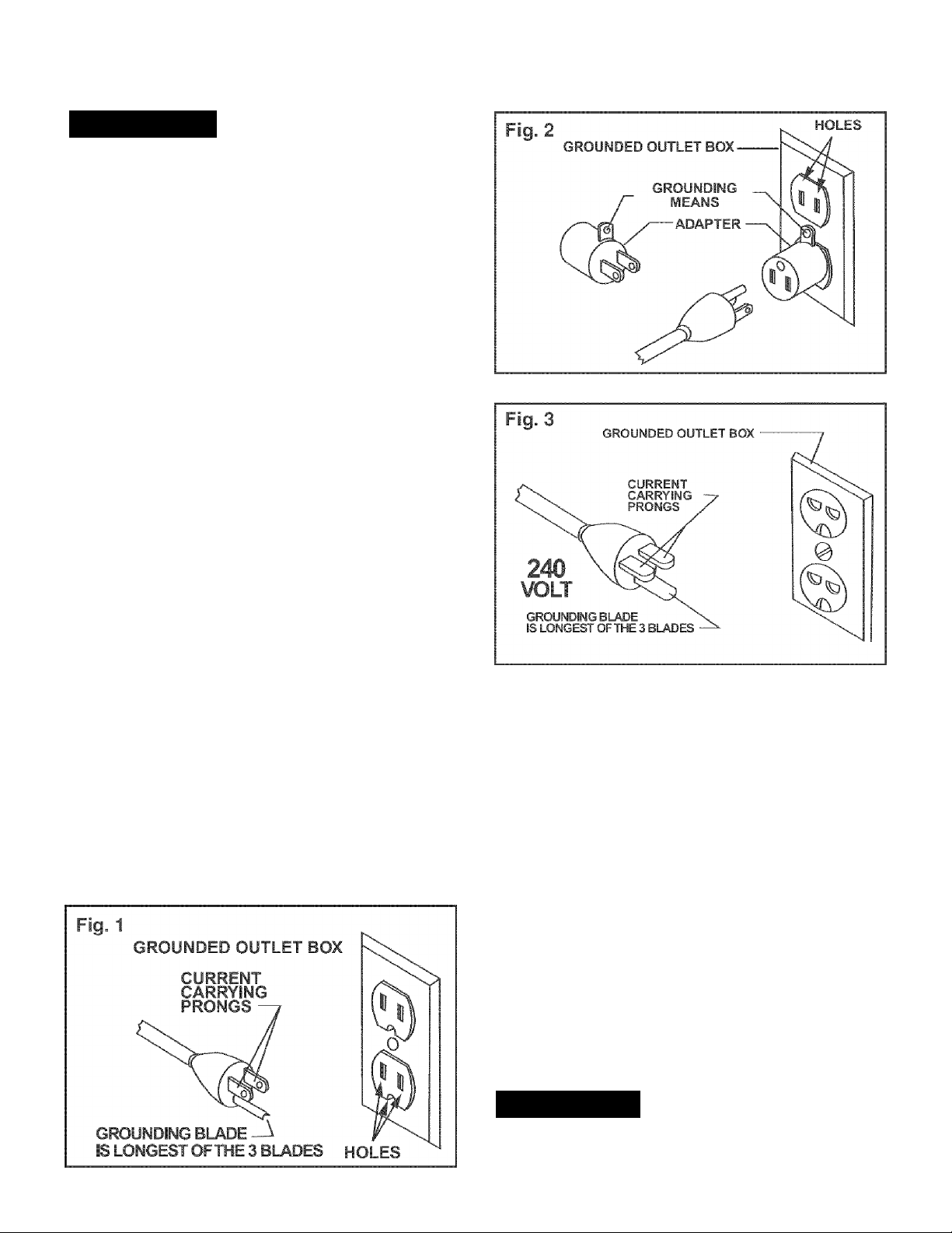
This tool is intended for use on a circuit that has an
electrical receptacle as shown in FIGURE 1. FIGURE 1
shows a 3-wire electrical plug and electrical receptacle
that has a grounding conductor. If a properly grounded
electrical receptacle is not available, an adapter as
shown in FIGURE 2 can be used to temporarily connect
this plug to a 2-contact ungrounded receptacle. The
adapter has a rigid lug extending from it that MUST be
connected to a permanent earth ground, such as a
properly grounded receptacle box. THIS ADAPTER IS
PROHIBITED IN CANADA.
A tool with a 240-volt plug should only be connected to
an outlet having the same configuration as the plug
shown in FIGURE 3. No adapter is available or should
be used with the 240-volt plug.
CAUTION: In all cases, make certain the electrical
receptacle in question is properly grounded. If you are
not sure have a certified electrician check the electrical
receptacle.
Awarning
This Dust Collector is for indoor use only. Do not
expose to rain or use in damp locations.
Page 6

SPECIFIC SAFETY INSTRUCTIONS FOR DUST COLLECTORS
12. USE only as described in this manual. USE acces
sories only recommended by Sears.
The operation of any Dust Collector can result in debris
being thrown into your eyes, which can result in severe
eye damage. ALWAYS Wear Safety Goggles (that com
ply with ANSI standard Z87.1) when operating the Dust
Collector. Safety Goggles are available at Sears Retail
Stores. Keep your thumbs and fingers away from intake
ports.
Basic precautions should always be followed when using
your dust collector. To reduce the risk of injury, electrical
shock or fire, comply with the safety rules listed below:
1. READ and understand the instruction manual
before operating the dust collector.
2. DO NOT OPERATE THIS MACHINE until it is
assembled and installed according to the instruc
tions.
3. OBTAIN ADVICE FROM YOUR SUPERVISOR,
instructor, or another qualified person if you are not
familiar with the operation of this machine.
4. DO NOT leave the dust collector plugged into the
electrical outlet Unplug dust collector from the out
let when not in use and before servicing, changing
bags, unclogging and cleaning.
13. DO NOT pull the dust collector by the power cord.
NEVER allow the power cord to come in contact
with sharp edges, hot surfaces, oil or grease.
14. DO NOT unplug the dust collector by pulling on the
power cord. ALWAYS grasp the plug, not the cord.
15. REPLACE a damaged cord immediately. DO NOT
use a damaged cord or plug. If the dust collector is
not operating properly, or has been damaged, left
outdoors or has been in contact with water, return it
to a Sears Service Center.
16. DO NOT use the dust collector as a toy. DO NOT
use near or around children.
17. DO NOT insert fingers or foreign objects into the
dust intake port. Keep hair, loose clothing, fingers,
and all body parts away from openings and moving
parts of the dust collector.
18. DO NOT use the dust collector without the dust
collection bag in place and properly secured.
19. ALWAYS use safety gates or caps to cover dust
ports when the dust collector is not in use or
mounted to a supporting surface for storage.
5. ALWAYS turn the power switch "OFF" before
unplugging the dust collector.
6. TO REDUCE THE RISK OF ELECTRICAL
SHOCK, do not use outdoors. Do not expose to
rain. Store indoors. Use only for dry pick up.
7. FOLLOW all electrical and safety codes, including
the National Electric Code (NEC) and the Occu
pational Safety and Health Regulations (OSHA). All
electrical connections and wiring should be made
by qualified personnel only.
8. DO NOT handle the plug or dust collector with wet
hands.
9. DO NOT use the dust collector to pick up flam
mable or combustible liquids, such as gasoline.
NEVER use the dust collector near any flammable
or combustible liquids.
10. USE the dust collector to pick up wood materials
only. DO NOT use the dust collector to pick up
metal shavings, metal dust, or parts.
20. PERIODICALLY INSPECT dust bag for any cuts,
rips or tears. NEVER operate the dust collector with
a damaged bag or vacuum hose.
21. The dust collector is designed for home use or light
commercial duty ONLY.
22. CONNECT dust collector to a properly grounded
outlet only. See grounding instructions.
23. ADDITIONAL INFORMATION regarding the safe
and proper operation of this product is available
from the National Safety Council, 1121 Spring Lake
Drive, Itasca, IL 60143-3201 in the Accident Pre
vention Manual for Industrial Operation and also in
the Safety Data Sheets provided by the NSC.
Please also refer to the American National Stand
ards Institute ANSI 01.1 Safety Requirements for
Woodworking Machinery and the U.S. Department
of Labor OSHA 1910.213 Regulations.
24. SAVE THESE INSTRUCTIONS. Refer to them
frequently and use them to instruct other users.
11. NEVER use the dust collector to dissipate fumes or
smoke. NEVER pick up anything that is burning or
smoking, such as cigarettes, matches or hot ashes.
Page 7

AVAILABLE ACCESSORIES
Visit your Sears Hardware Department or see the Sears
Power and Hand Tool Catalog for the following acces
sories.
Sears may recommend other accessories not listed in
this manual.
See your nearest Sears Hardware Department or Sears
Power and Hand Tool Catalog for other accessories.
ITEM
30 micron filter bag (top)
5 micron filter bag (top)
Plastic collection bag (bottom)
4" Diameter X 10' flexible hose
4" Diameter x 25' flexible hose
Various accessory fittings
STOCK NUMBER
21379
21380
21381
21372
21373
See catalog or store
Do not use any accessory unless you have completely
read the Owner's Manual for that accessory.
Awarning
Use only accessories recommended for this Dust
Collector. Using other accessories may cause serious
injury and cause damage to the Dust Collector.
Page 8
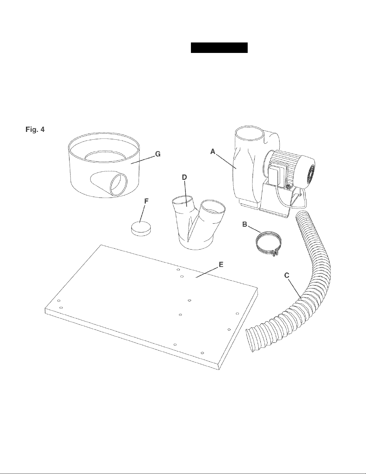
UNPACKING AND CHECKING CONTENTS (Figure 4 and Figure 5)
This Dust Collector will require a minimal amount of
assembly.
Remove all of the parts from the shipping box and lay
them on a clean work surface. Compare the items to
Figure 4 and Figure 5, verify that all items are account
ed for before discarding the shipping box.
Awarning
If any parts are missing, do not attempt to plug in the
power cord and turn "ON" the Dust Collector. The Dust
Collector can only be turned "ON" after all the parts
have been obtained and installed correctly.
A. Blower and motor Assembly E. Base
B. 4-inch Hose Clamp F. Intake Port Caps (2)
C. 4-inch Diameter Flexible Hose
D. Intake Port
G.
Drum
Page 9
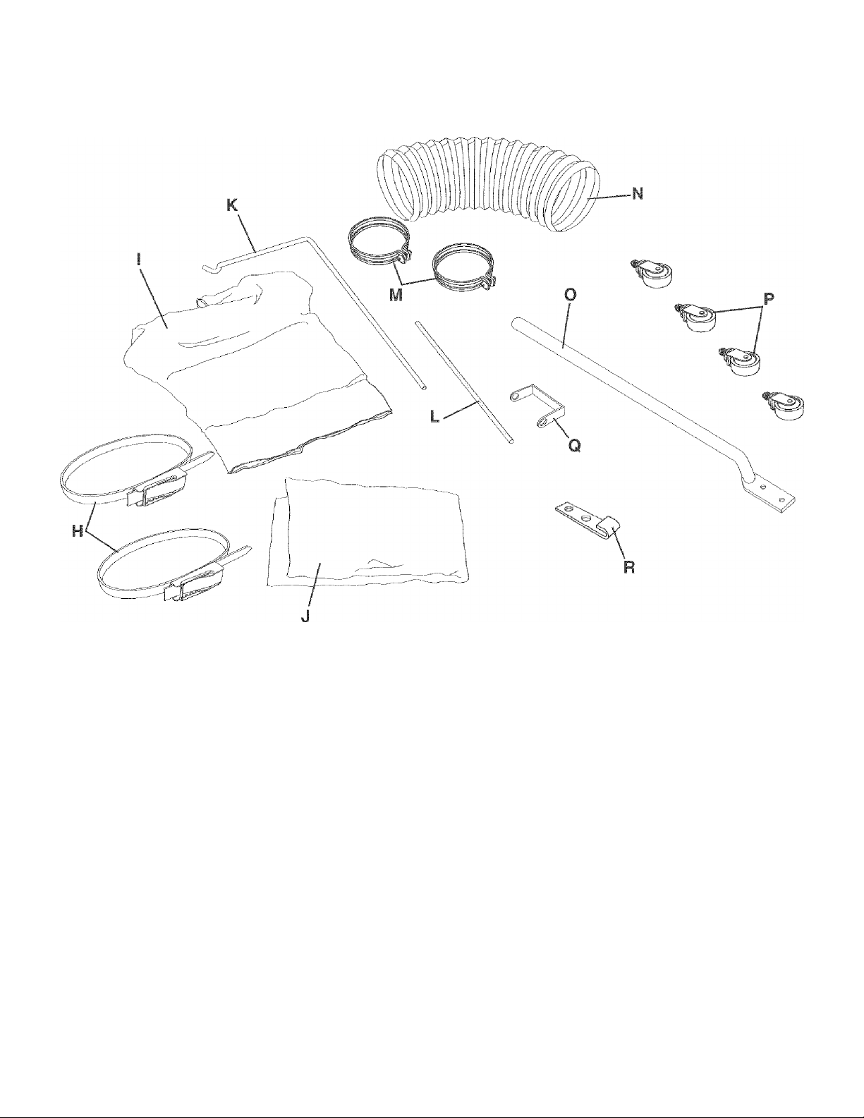
Fig. 5
H. Locking Band (2)
I. Filter Bag
J. Collection Bag
K. Upper Support Rod
L. Lower Support Rod
M. 6-inch Hose Clamp (2)
N. 6-inch Diameter Flexible Hose
O. Drum Support (3)
P. Caster Assembly (4)
Q. U-Bracket
R. Retaining Clip (4)
HARDWARE NOT SHOWN
* 5/16-18 X 5/8" Hex Head Screw (20)
* 5/16" Lock Washer (24)
* 5/16-18 Hex Nut (12)
* 5/16" X 7/8" O. D. Flat Washer (6)
* 1/4-20 X 5/8" Hex Head Screw (8)
* 1/4" Lock Washer (8)
* 1/4-20 Hex Nut (8)
* M4.2 Sheet Metal Screw (4)
Page 10
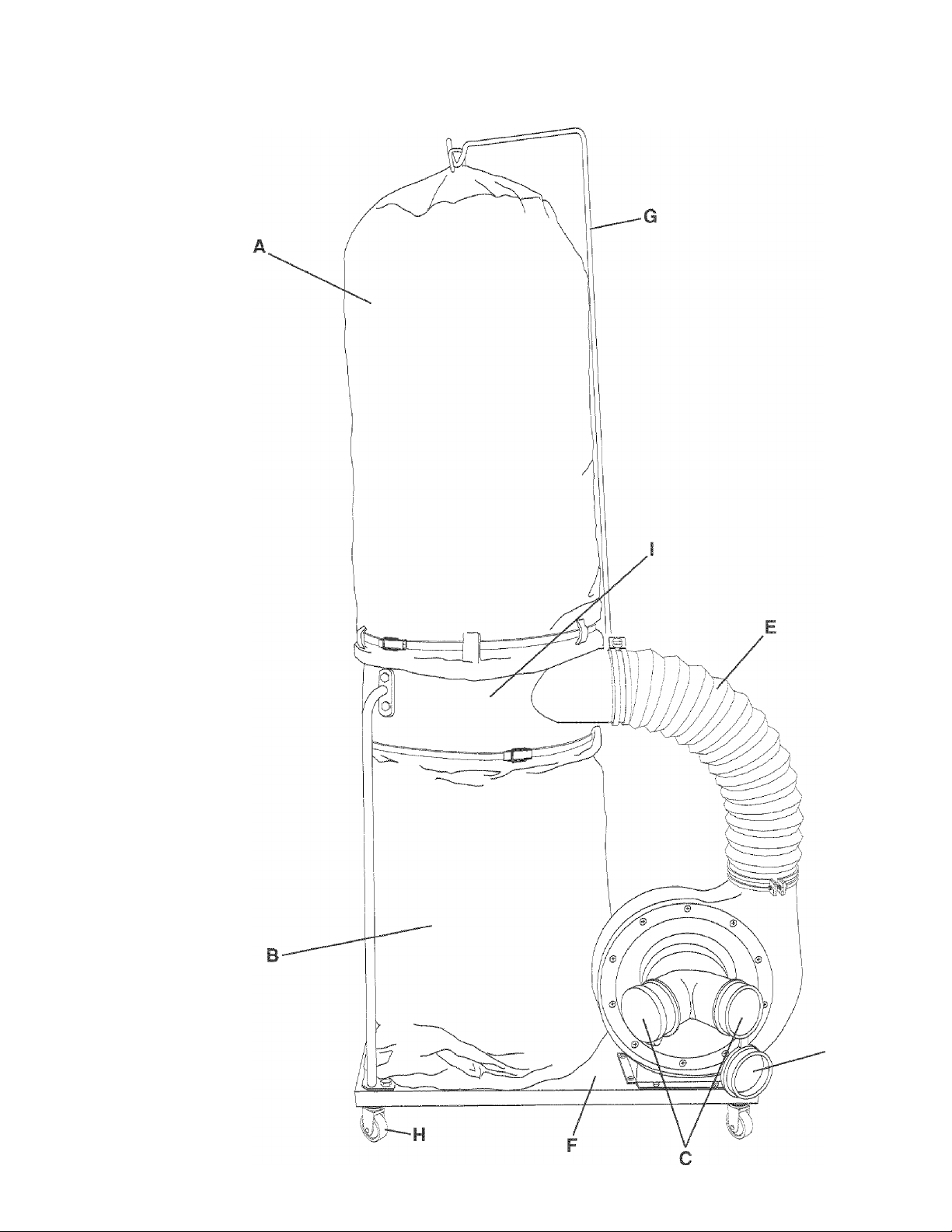
Fig. 6
A. Filter Bag
B. Collection Bag
C. 4-inch Intake Port
D. Intake Port Cap
E. 6-inch Flexible Hose
F. Base
G. Support Rod
H. Caster
I. Drum
10
Page 11
Awarning
1. DO NOT assemble the Dust Collector until you are
sure the tool IS NOT plugged in.
2. DO NOT assemble the Dust Collector until you are
sure the power switch is in the "OFF" position.
2. For your own safety, DO NOT connect the machine
to the power source until the machine is completely
assembled and you read and understand the entire
Owner's Manual.
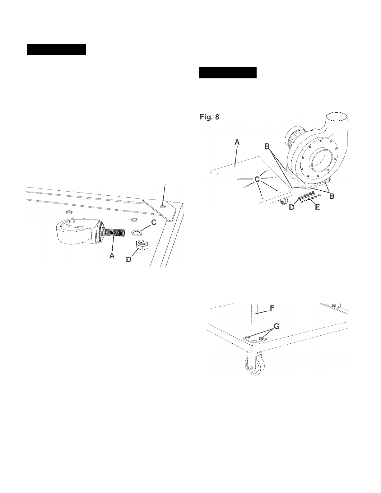
CASTER TO BASE ASSEMBLY
Fig. 7
B
BLOWER AND MOTOR ASSEMBLY
TO BASE ASSEMBLY
Awarning
MAKE CERTAIN THE DUST COLLECTOR IS
DISCONNECTED FROM THE POWER SOURCE.
Turn base (A) right side up. Align the mounting
holes at the base of blower and motor assembly (B)
with six pre-drilled holes (C) in base and fasten with
six 5/16-18 X 5/8" hex head screws (D) and 5/16"
lock washer (E). See figure 8.
1. Insert threaded rod of caster (A) into the hole
located on the underside of base (B) and fasten
with 3/8" lock-washer (C) and 3/8-16 hex nut (D).
See figure 7.
2. Assemble the remaining three casters to the under
side of the base in the same manner.
Fig. 9
Assemble drum support (F) to the two threaded
holes in the corner of base with two 5/16-18 x 5/8"
hex head screws and 5/16" lock washer (G). NOTE:
Do not completely tighten hardware at this time.
See figure 9.
Assemble the remaining drum supports to the base
in the same manner. NOTE: Do not completely
tighten hardware at this time.
11
Page 12
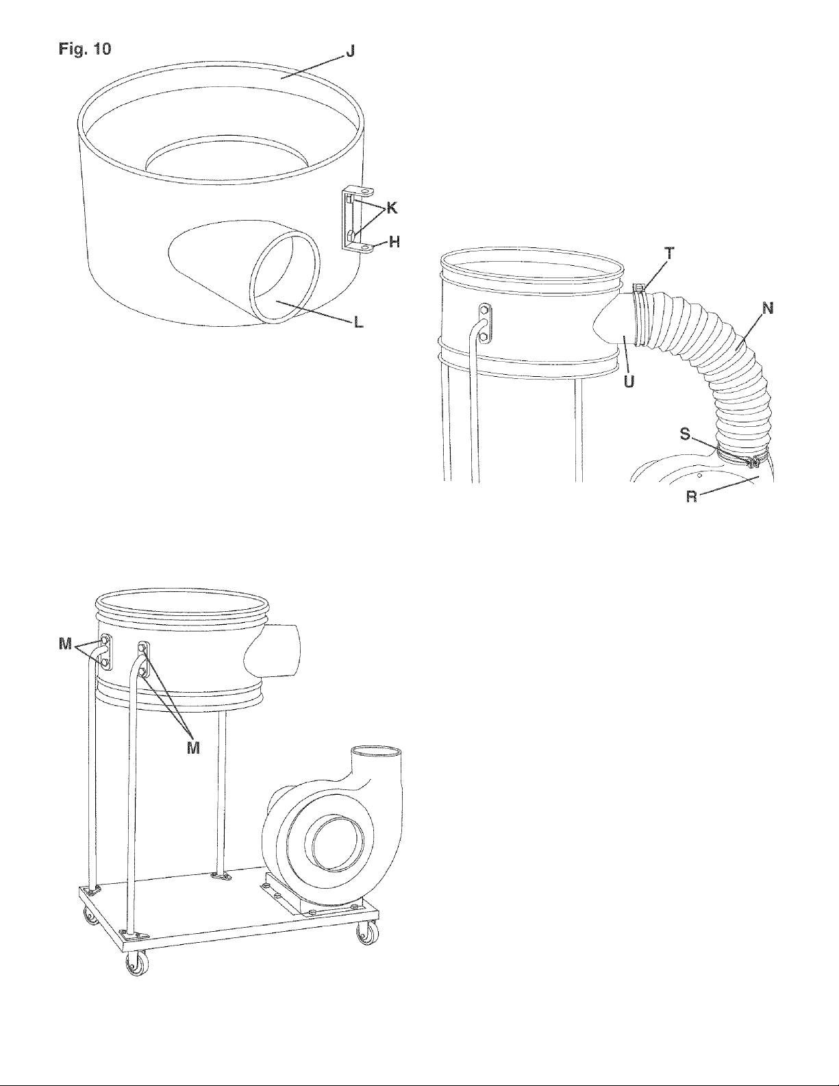
Assemble U-Bracket (H) to Drum (J). Place a 5/16"
lock washer then a 5/16" flat washer onto a 5/1618 X 5/8" hex head screw (K) thru the hole in the
U-Bracket and the hole in the drum, thread a 5/16"
hex nut onto the hex head screw. Repeat this
process for the remaining hole and securely tighten
both screws. NOTE: U-Bracket should be mounted
to the right side of opening (L) in the drum as
shown. See figure 10.
Align the holes in the drum support with the holes in
the drum (M). Place a 5/16" lock washer on a 5/16-
18 X 5/8" hex head screw, then 5/16" flat washer
onto the hex head screw. Insert the hex head screw
thru the hole in drum support and drum. Thread a
5/16" hex nut onto the hex head screw and tighten
securely. See figure 11. Fasten the remaining
drum supports to the drum in the same manner.
Fig. 12
Fig. 11
Place one end of 6-inch diameter flexible hose (N)
over blower/motor outlet(R). Slide one 6-inch
diameter hose clamp (S) down 6-inch flexible hose
and tighten hose clamp to blower/motor outlet.
See figure 12.
7.
Place the other 6-inch hose clamp (T) over the
6-inch flexible hose. Attach the 6-inch flexible hose
to the drum inlet (U) and tighten 6-inch hose clamp.
See figure 12.
12
Page 13
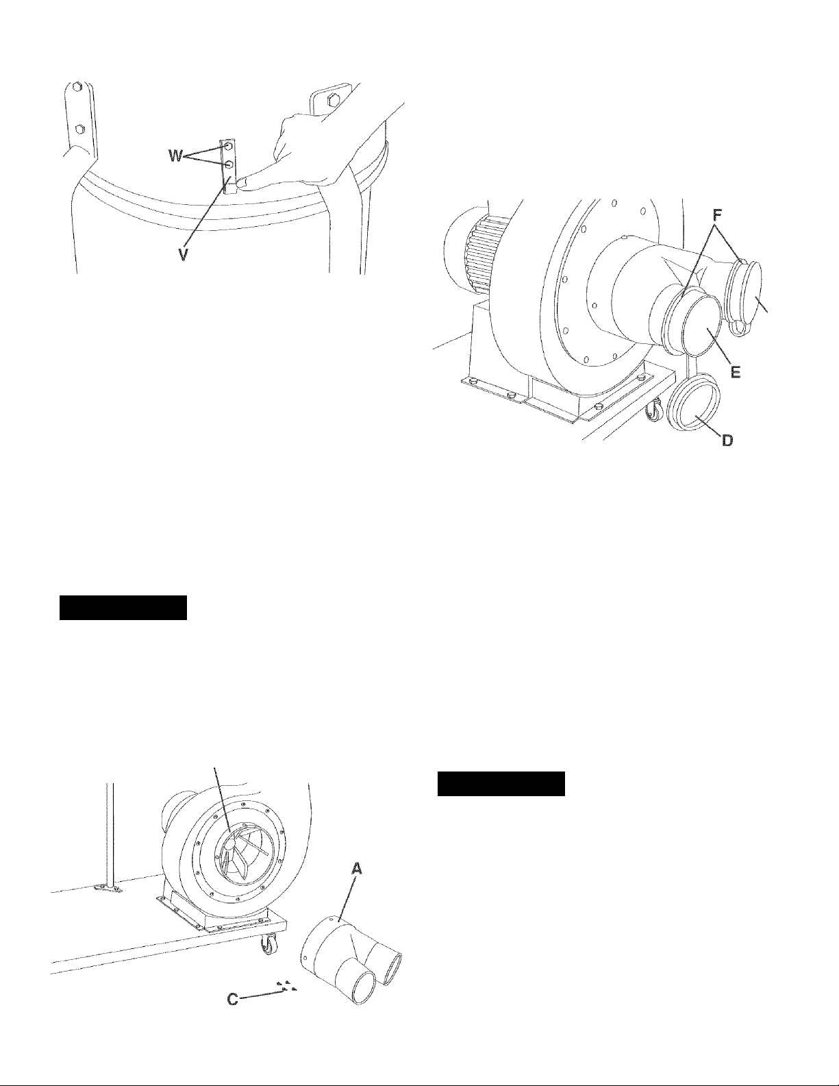
Fig. 13
Attach the lower dust bag retaining clip (V) to the
dust collector drum. Align both holes (W) in the
retaining clip with the two holes In the drum. Insert
a 1/4-20 X 5/8" hex head screw through each hole
in the retaining clip and drum. Place a 1/4" flat
washer and 1/4-20 hex nut onto screw inside of the
drum. Repeat this process for the other three
retaining clips and tighten all hardware.
See figure 13.
1. Align the four holes in intake port (A) with the
mounting holes in flange (B) of blower and motor
assembly and fasten with four M4.2 sheet metal
screws (C). See figure 14.
Fig. 15
INTAKE PORT TO BLOWER MOTOR ASSEMBLY
Awarning
MAKE CERTAIN THE DÜST COLLECTOR
DISCONNECTED FROM THE POWER SOURCE.
Fig. 14
B
2. Attach one intake port cap (D) to the intake port (E).
The intake port caps must be placed into the intake
ports when the intakes are not in use.
See figure 15.
IMPORTANT: When connecting an intake hose to one
or both intake ports, DO NOT REMOVE THE INTAKE
PORT CAP COLLARS (F) FROM THE INTAKE
PORTS. Slide the collar further back when attaching a
hose. See figure 15.
FILTER AND COLLECTION BAG
TO DRUM ASSEMBLY
Awarning
MAKE CERTAIN THE DUST COLLECTOR IS
DISCONNECTED FROM THE POWER SOURCE.
1. Hook the loop (A) on the top filter bag onto hook
(B) of the upper support rod. See figure 17.
13
Page 14
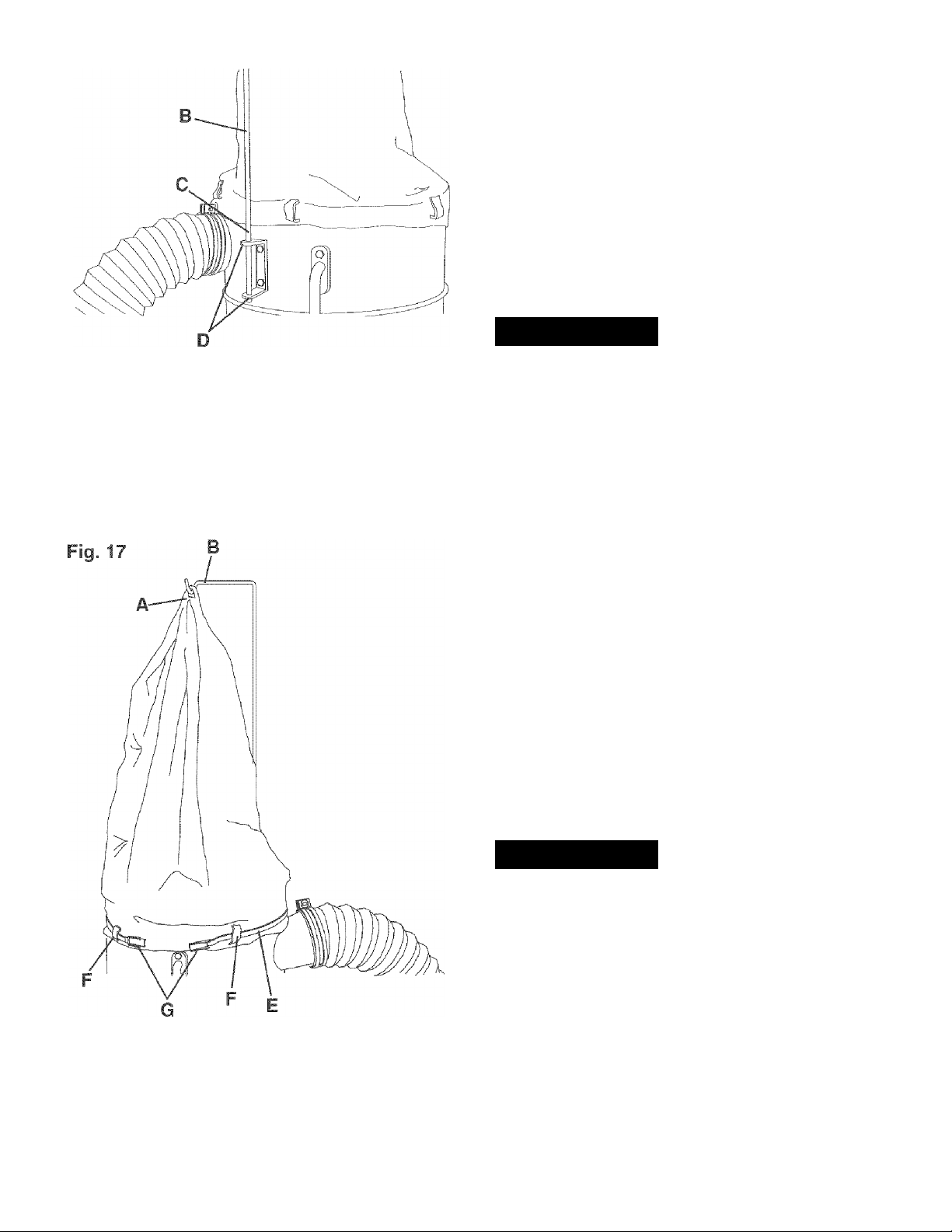
Fig. 16
Place the second locking band through all the loops
of the collection bag, similar to the filter bag.
Place the collection bag over the lower lip of the
drum. Pull up on the retaining clips and insert col
lection bag underneath each retaining clip. Make
certain the locking band is positioned in the lower
recessed channel of the drum and fasten clamp
securely to drum.
FLEXIBLE HOSE TO
INTAKE PORT ASSEMBLY
A WARNING
Slide the lower support rod (C) onto the end of
the upper support rod (B). Raise the assembled
support rod with filter bag attached and place the
end of the lower support rod into the holes of the
U-bracket (D). The flared end of lower support
rod will prevent the rod from sliding through the
U-bracket. See figure 16.
MAKE CERTAIN THE DUST COLLECTOR
DISCONNECTED FROM THE POWER SOURCE.
IMPORTANT: When connecting an intake hose to one
or both intake ports, DO NOT REMOVE THE INTAKE
PORT CAPS FROM THE INTAKE PORTS. Slide the
collar further back the intake port when attaching a
hose.
1. To attach the 4-inch flexible hose to one of the
intake ports, pull the intake port cap from the intake
port. Slide the collar of the intake port cap further
back the intake port and let the cap hang from the
intake port.
2. Place 4-inch hose clamp over 4-inch flexible hose.
Slide hose over one intake port opened Step 1
above and tighten hose clamp.
3. If you wish to use the second intake port, you
should purchase a second 4-inch flexible hose and
4-inch hose clamp and repeat Steps 1 and 2 above.
See your nearest Sears Hardware Department or Sears
Power and Hand Tool Catalog for other accessories.
3. Insert locking band (E) through all the loops of filter
bag (F). Position the open end of the filter bag over
the top lip of the drum. Make certain the locking
band is positioned in the upper recessed channel of
the drum and fasten clamp (G) securely to drum.
See figure 17.
A WARNING
Use only accessories recommended for this Dust
Collector. Using other accessories may cause serious
injury and cause damage to the Dust Collector.
14
Page 15
Awarning
START/STOP SWITCH
FOR OPERATOR SAFETY, keep fingers and all foreign
objects out of the intake ports. The rotating fan inside
the blower housing is accessible through the intake
ports and is hazardous. Do not wear loose clothing or
jewelry. Make certain that each intake port which is not
being used or attached to a dust collection system is
covered with an intake port cap.
CONNECTING TOOL TO POWER SOURCE
A separate electrical circuit should be used for your
tools. This circuit should not be less than #14 A. W. G.
wire and should be protected with a 15-amp time lag
fuse. Have a qualified electrician repair or replace dam
aged or worn cord immediately. Before connecting the
motor to the power line, make certain the switch is in
the "OFF" position and be sure that the electric current
is of the same characteristics as stamped on the motor
nameplate. All line connections should make good con
tact. Running on low voltage will damage the motor.
Awarning
DO NOT EXPOSE THE DUST COLLECTOR TO RAIN
OR OPERATE THE MACHINE IN DAMP LOCATIONS.
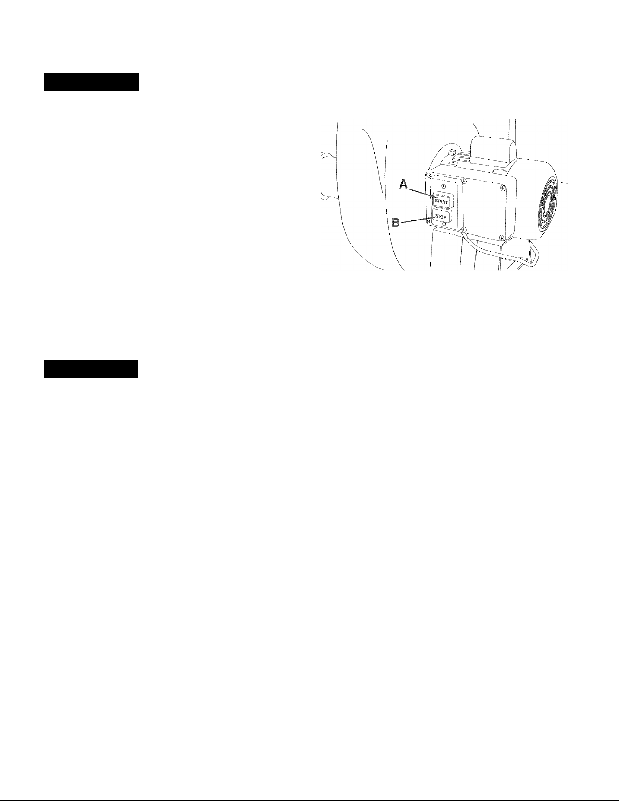
Fig. 18
The START/STOP switch is located on the side of the
motor. To turn the dust collector "ON", push the green
start button (A). To turn the dust collector "OFF", push
the red stop button (B). See figure 18.
LOCKING SWITCH IN
THE "OFF" POSITION
When the Dust Collector is not in use, the start button
can be locked so that it cannot be started. Using a
padlock (included) through the holes in the side of the
start button.
CIRCUIT BREAKER
Your dust collector motor is supplied with a resettable
circuit breaker. It is located on top of the starTstop
switch box on the side of the motor. If the motor shuts
off or fails to start due to an overload condition, turn the
dust collector "OFF," let the motor cool for three to five
minutes, and push the reset button on the circuit
breaker to reset the breaker. The motor can then be
turned on again in the usual manner.
15
Page 16

CHANGING MOTOR VOLTAGE
1. DISCONNECT THE DUST COLLECTOR FROM
THE POWER SOURCE.
Awarning
MAKE CERTAIN THE DUST COLLECTOR IS
DISCONNECTED FROM THE POWER SOURCE.
The motor supplied with your Dust Collector is a dual
voltage 120/240-volt, single-phase motor. It is shipped
wired for 120-volt application. If you choose 240-volt to
operate your machine, the following instructions must
be followed.
Awarning
If you are unsure of electrical connections or codes,
contact a certified electrician. All local and state codes
must be followed.
Refer to GROUNDING INSTRUCTION section before
proceeding:
ON/OFF SWITCH CIRCUIT BREAKER
—‘'XI
2. Remove the switch box cover.
3. The motor has four leads. Reconnect the motor
leads for chosen voltage, as shown in the wire
diagram. See figure 19.
4. The START/STOP switch is a double pole switch.
No changes are required for 120/240 volt operation.
5. Replace the plug with the correct plug with ground
for voltage required. The new plug must meet all
local and state electrical codes.
6. Reassemble switch box cover.
... 1. .1
3 / \
2 1 iviu i UH 1
4 V
J
120 VOLT CONNECTION
ON/OFF SWITCH CiRCUIT BREAKER
______
-----------------------------------
240 VOLT CONNECTION
Fig. 19
A
^
<
16
Page 17

Below are some terms that will help you to understand
and setup your Dust Collector and design your own
Dust Collection System.
Dust Collector - A machine used to collect fine wood
dust and chips.
Dust Collection System - A dust collector connected
to multiple woodworking machines utilizing various
types of hose/pipe and fittings.
C.F.M. = Cubic Feet/Minute - A measurement of the
amount of air volume that can move through a dust
collector in one minute.
Static Pressure - A measurement of the amount of the
resistance to airflow in a dust collection system.
HELPFUL HINTS:
• Always run the largest appropriate diameter hose
as far as possible. Running a smaller diameter hose
will greatly reduce the C.F.M. at the tool, yielding
marginal dust collection.
• The use of a low rated micron filter and collection
bag can increase the effectiveness of your dust
collector in removing fine particles of dust.
• Determine if you are to use your Dust Collector in a
Dust Collection System or as a direct hook-up to an
individual tool. If used in a Dust Collection System,
review Static Pressure Requirements below.
Awarning
To protect yourself from a static shock, ground the dust
collection system to a known ground.
THINGS TO CONSIDER:
• What is the maximum C.F.M. required for each tool
you intend to use? Your Dust Collector should be
rated for the tool that has the highest C.F.M.
requirement.
• Will two or more tools be running at the same time?
The Dust Collector should be rated to handle the
combined C.F.M. requirements of all operating tools.
If using the Dust Collector in a Dust Collector System,
make certain to:
• Ground the dust collection system to a known ground.
• Always keep blast gates closed to unused tools.
• Make all runs as short as possible, minimizing the
number of bends or turns that could greatly reduce
the efficiency of your Dust Collector.
• Position the tools that have the highest C.F.M.
ratings closest to the Dust Collector.
17
Page 18

C.F.M. REQUIREMENTS FOR TOOLS
Machine Minimum C.F.M. Required Minimum Duct Diameter
Band Saw (12 to 16-inch) 350 C.F.M. 4-inch
Belt/Disc Sander 450 C.F.M. 5-inch
Drill Press 350-400 C.F.M. 4-inch
Drum Sander (12 to 24-inch) 550-700 C.F.M. 5-inch
Floor Sweep 350-400 C.F.M. 4 to 5-inch
Jointer (up to 8-inch) 350-400 C.F.M. 4 to 5-inch
Jointer (over 8-inch) 450-550 C.F.M. 5-inch
Radial Arm Saw 450-600 C.F.M. 5-inch
Miter Saw 450-600 C.F.M. 5-inch
Router Table 200 C.F.M. 3-inch
Scroll Saw 200 C.F.M. 3-inch
Spindle Sander 400 C.F.M. 4-inch
Table Saw (10-inch) 350 C.F.M. 4-inch
Thickness Planer (10 to 15-inch) 400 C.F.M. 4-inch
Thickness Planer (16 to 20-inch) 600-800 C.F.M. 5 to 6-inch
STATIC PRESSURE REQUIREMENTS FOR A DUST COLLECTION SYSTEM
Using STEPS 1 thru 4 and the “Static Pressure Requirement Chart” you can determine the static pressure required
for your Dust Collector.
Step #1: Multiply the number of feet of Hose/Pipe times the appropriate inches rating.
Example: AQ feet of 4-inch diameter ribbed tubing x .11 =4.4 Total
Step #2: Multiply the fittings times the ratings and add them together.
Example:Jvio 90-degree Elbows (using 4-inch diameter Hose) = .84 PLUS two 90-degree T-fittings = .98
Total = 1.82
Step #3: Add 2.5 for the Machine Hook-up and “Dirty Bag" factors (1.5 for Hook-ups + 1.0 for Dirty Bag).
Step #4: Total the above three calculations. This total should not exceed the maximum static
pressure for your Dust Collector.
Example: AA (Total Step #1) x 1.82 (Total Step #2) + 2.5 (Total Step #3) = 8.72
For this example a Dust Collector with a Static Pressure rating of over 8.72 or higher is required.
See Product Specifications on page 2 for your dust collector maximum static pressure.
NOTE: To determine if you have met the Static Pressure Requirement when using a Dust Collection System, identify
the branch of the system with the highest static pressure requirement first. If you run your Dust Collection System with
more than one blast gate open, add the static pressure from all branches that are open to determine the total static
pressure requirements.
Static Pressure Requirement Chart
Size of Hose Hose/Pipe
Rigid Pipe
(per foot)
Ribbed Tubing
(per foot)
90-degree
Elbow
90-degree
Elbow
45-degree
T-fitting
Machine
Hook-Up
“Dirty Bag”
Adjustment
3 .10 .15 .50 .60 .25 1.50 1.0
4 .07 .11 .42 .49 .21 1.50 1.0
5 .055 .08 .49 .55 .25 1.50 1.0
18
Page 19

To purchase any of the Dust Collection Accessories listed below, visit your nearest Sears Store.
Various Fittings:
21340 3-inch Hose Coupling
21363 3-inch 90-degree Elbow
21365 3-inch Y-Fitting
21367 3-inch T-FItting
Hose:
21370 3-inch X 10-foot Flexible Hose
21371 3-inch X 25-foot Flexible Hose
21372 4-inch X 10-foot Flexible Hose
21373 4-inch X 25-foot Flexible Hose
Blast Gates
21359 3-inch Blast Gate - Plastic
21361 3-inch Blast Gate - Aluminum
Reducers:
21347 5 to 4-inch Reducer
21349 4 to 2-1/2-inch Reducer
21352 3 to 2-inch Reducer
21341 4-inch Hose Coupling
21364 4-inch 90-degree Elbow
21366 4-inch Y-Fitting
21368 4-inch T-Fitting
21360 4-inch Blast Gate - Plastic
21362 4-inch Blast Gate - Aluminum
21348 4 to 3-inch Reducer
21351 3 to 2-1/2-inch Reducer
21353 2-1/2 to 1-1/2-inch Reducer
Hose Clamps {Qty 2 per Pack)
21354 2-inch Hose Clamp
21356 3-inch Hose Clamp
21358 5-inch Hose Clamp
Dust Hoods:
21342 Jointer Dust Hood, 8-1/4" x 8-1/4" x 4" Diameter
21343 Jointer Dust Hood, 10-1/4" x 8-1/2" x 4" Diameter
21344 Table Saw Dust Hood, 12-1/4" x 12-1/4" x 4" Diameter
21345 Table Saw Dust Hood, 14" x 14" x 4" Diameter
21346 Universal Dust Hood, 6-1/4" x 6-1/4" x 4" Diameter
Floor Sweep:
21369 Floor Sweep
Kits:
21350 Wall Mounting Kit
21375 Dust Collector Accessory Kit
(contains: 6 - wall damps, 12-screws & 12-anchors)
(contains: 2-#21372, 1-#21344, 1-#21342, 1-#21346, 4-#21360, 1-#21369,
1-#21366, 1-#21350 & 5-#21357)
21355 2-1/2-inch Hose Clamp
21357 4-inch Hose Clamp
19
Page 20

Awarning
Turn the power switch "OFF" and unplug the power
cord from its power source prior to any maintenance.
Always make sure that the intake port caps covers the
intake port when a hose is not connected to the dust
collector.
air may damage insulation. The operator should always
wear eye protection when using compressed air.
Do not allow chips and dust to accumulate under dust
collector. Keep area clean and in safe order.
LUBRICATION
The Dust Collector has sealed lubricated bearings in
the motor housing that does not require any additional
lubrication from the operator.
CLEANING
With the Dust Collector unplugged, blow off motor with
low pressure air to remove dust or dirt. Air pressure
above 50 P. S. I. should not be used as high-pressured
CAUTION: DO NOT USE FLAMMABLE MATERIALS
to clean Dust Collector.
Awarning
Repairs to the Dust Collector should be performed by
trained personnel only. Contact your nearest Sears
Service Center for authorized service. Unauthorized
repairs or replacement with non-factory parts could
cause serious injury to the operator and damage to the
Dust Collector.
TROUBLESHOOTING GUID
TO PREVENT INJURY TO YOURSELF or damage to the Dust Collector, turn the switch to the “OFF” position and
unplug the power cord from the electrical receptacle before making any adjustments.
PROBLEM LIKELY CAUSE(S) SOLUTION
Motor does
not start
1. Switch not pressed in far enough or
switch in the “OFF” position
2. Defective switch
3. Defective capacitor
4. Low line voltage
5. Defective motor
1. Depress switch in 1/2 inch or make sure switch
is in the "ON" position.
2. Have switch replaced.
3. Have capacitor replaced.
4. Correct low line voltage condition.
5. Have motor replaced/repaired.
NOTE: 2, 3 and 4 must be done by a qualified service
technician: Contact Sears service.
Motor stalls
(resulting in blown
fuses or tripped
circuit breakers)
Motor starts
slowly or fails to
come to full speed
Motor running
too hot
Frequent opening
of fuse or circuit
breakers
1. Circuit overload
2. Low line voltage
3. Chips or debris clogged impeller.
4. Motor overload
5. Incorrect fuses on circuit breakers
6. Short circuit in motor; loose connections
or worn insulation on lead wires
1. Defective motor windings
2. Defective capacitor
1. Restricted air circulation due to dust
accumulation.
2. Motor overload
1. Fuses or circuit breakers do not have
sufficient capacity
2. Circuit overloaded
3. Motor overload
20
1. Reduce circuit load
2. Correct low line voltage condition.
3. Clean all hoses, bags and blower housing of chips
and debris.
4. Reduce load on motor.
5. Have correct fuses on circuit breakers installed.
6. Inspect terminals in motor for damaged insulation
and shorted wires and have them replaced.
1. Have motor replaced/repaired.
2. Have capacitor replaced.
1 A. Clean dust and restore normal air circulation.
1B. Empty and clean filter and collection bags.
2. Reduce load on motor.
1. Have correct fuses or circuit breakers installed.
2. Reduce circuit load (turn off other appliances).
3. Reduce load on motor.
Page 21

DUST COLLECTOR PARTS LIST MODEL N0.152.213371
Awarning
When servicing, use only CRAFTSMAN replacement parts. Use of any other parts may create a HAZARD or cause
product damage.
Awarning
Any attempt to repair or replace electrical parts on this Dust Collector may create a HAZARD unless repair is done by
a qualified service technician. Repair service is available at your nearest Sears Service Center.
Always order by PART NUMBER, not by key number.
Key No. PART No. Description Qty. Key No. PART No. Description Qty.
1 OR90672 UPPER HANGER (COLOR: PANTONE 877) 1 40 OR90685 PAN HEAD SCREW M4.2 X 10MM 6
2 OR90673 LOWER RANGE (COLOR: PANTONE 877) 1 41 OR9Q690 SWITCH PLATE (COLOR: BLACK) 1
3 OR90674 U-BRACKET (COLOR: PANTONE 877) 1 42 OR90374 HEX NUT #10-24 1
4
STD523106 HEX HEAD SCREW 5/16-18 X 5/8" 2 43 OR90689 EXT TOOTH WASHER 3/16" 2
5 OR90615 LOCK WASHER 5/16“ 2
6 STD551031 FLAT WASHER 5/16" 2 45 OR90692 HEX NUT #6-32 2
7 STD541031 HEX NUT 5/16-18 2
8 OR65979 FILTER BAG, 30 MICRON 1 47 OR9Q694 SWITCH 1
9 OR90675 BAND CLAMP 1 48 OR90695 SWITCH COVER ASSEMBLY 1
*10 OR90676 DRUM ASSEMBLY (COLOR: PANTONE 877)
11 STD541031 HEX NUT 5/16-18 2
12 STD551031 FLAT WASHER 5/16" 2 INCLUDES: 1-OR90698. 1-OR90600 &
13 OR90615 LOCK WASHER 5/16" 2
14 STD523106 HEX HEAD SCREW 5/16-18 X 5/8" 2
15 STD522506 HEX HEAD SCREW 1/4-20 X 5/8“ 8
16 OR90706 RETAINING CLIP
17 STD551025 FLAT WASHER 1/4" 8
18 STD541025 HEX NUT 1/4-20 8
19 OR90675 BAND CLAMP 1
20 OR90713 COLLECTION BAG. 30 MICRON 1
21 OR90705 DRUM SUPPORT (COLOR: PANTONE 877) 3
22 STD52310e HEX HEAD SCREW 5/16-18 X 5/8" 6
23 OR90615 LOCK WASHER 5/16" 6
24 OR90678 6" HOSE CLAMP 1
25 OR90707 6" FLEXIBLE HOSE 1
26 OR90678 6" HOSE CLAMP 1
27 OR90708 GASKET 1
28 OR90709 MOTOR SHAFT KEY 5mm X 5mm X 27mm 1
29 STD541031 HEX NUT 5/16-18
30 STD551031 FLAT WASHER 5/16" 4 67 OR90650 INTAKE PORT CAP 2
31 OR90710 MOTOR ASSEMBLY (COLOR: BLACK) 1 68 OR90711 CORD 1
32 OR90682 SWITCH BOX (COLOR: BLACK) 1 69 OR90712 CIRCUIT BREAKER 1
33 OR90683 CHEESE HEAD SCREW M5 X 20MM 4 70 OR90726 CIRCUIT BREAKER LABEL 1
34 OR90684 CLAMP 1 71 OR90715 SPECIAL NUT 1
35 OR90685 PAN HEAD SCREW M4,2 X 10MM 1 72 OR90615 LOCK WASHER 5/16" 6
36 OR90686 CAPACITOR 200uf 1 73 STD523106 HEX HEAD SCREW 5/16-18 X 5/8" 6
37 OR90687 PAN HEAD SCREW #6-32 X 5/16" 2 74 OR90718 PADLOCK WITH 2 KEYS (NOT SHOWN) 1
38 OR90688 EXT TOOTH WASHER #6 2 N/A OR9376 OWNERS MANUAL FOR MODEL #213371 1
39 OR90689 EXT TOOTH WASHER 3/16" 6
INCLUDES; 1-OR90677, 2-OR90608 &
1-OR90601
‘1
4
4
44
STD511003 PAN HEAD SCREW #10-24 X 3/8" 1
46 OR90693 SPACER 2
49
OR90696
50
OR93766
*51 OR90697 BLOWER HOUSING ASSEMBLY
52 OR90615 LOCK WASHER 5/16" 6
53 OR90635 HEX HEAD SCREW 5/16-18 X 5/8" 6
54 OR90699 BASE (COLOR: BLACK) 1
55 STD541037 HEX NUT 3/8-16 4
56 OR90647 LOCK WASHER 3/8"
57 OR90700 SWIVEL CASTER
58 OR65935 4“ HOSE CLAMP 2
59 OR90717 4" DIA. X 6' FLEXIBLE HOSE 1
60 OR90701 IMPELLER 1
61 STD551031 FLAT WASHER 5/16" 1
62 STD523107 HEX HEAD SCREW 5/16-18 X 3/4" 1
63 OR90702 COVER (COLOR: PANTONE 877) 1
64 OR90716 PAN HEAD SCREW M4.2 X 12mm 10
65 OR90716 PAN HEAD SCREW M4.2 X 12mm
*66 OR90703 INTAKE ASSEMBLY
ROUND HEAD SCREW #6-32
SPEC LABEL
(COLOR: PANTONE 877)
1-OR90612
(COLOR: PANTONE 877)
INCLUDES: 1-OR90704 & 1-OR90601
(NOT SHOWN)
1
*1
*1
2
4
4
4
21
Page 22

DUST COLLECTOR PARTS LIST MODEL N0.152.213371
Page 23

♦ NOTES ♦
23
Page 24

♦ NOTES ♦
24
Page 25

Manual del Propietario
CRRFTSMRN
PiPFESSiOWML
1-1/2 caballos de fuerza (servicio continuo)
2.1 caballos de fuerza (máximo desarrollado)
1200 C.F.M. (pies cúbicos por minuto)
3450 R.P.M. (R.P.M. sin carga)
COLECTOR DE POLVO
No. de Modelo
152.213371
PRECAUCION:
PARA su SEGURIDAD PERSONAL:
Lea y obedezca todas las
Instrucciones de Seguridad y
Funcionamiento antes de accionar
este Colector de Polvo.
Línea de Ayuda al Cliente
1 -800-897-7709
Sírvase tener listo su No. de
Modelo y No. de Serie
Sears, Roebuck and Co., Hoffman Estates, IL 60179 U.S.A.
No. de Pieza OR93765
25
Page 26

SECCION PAGINA
Garantía...........................................................................................................................................................................2
Especificaciones del Producto.....................................................................................................................................2
Instrucciones de Seguridad..........................................................................................................................................3
Instrucciones de Conexión a Tierra .............................................................................................................................5
Instrucciones de Seguridad Específicas para los Colectores de Polvo ..................................................................6
Accesorios y Aditamentos............................................................................................................................................?
Contenido de la Caja .....................................................................................................................................................8
Conozca su Colector de Polvo ...................................................................................................................................10
Instrucciones de Montaje ............................................................................................................................................11
Accionando el Colector de Polvo...............................................................................................................................15
Colector de Polvo en el Taller.....................................................................................................................................17
Mantenimiento........
......................................................................................................................................................
20
Guía de Localización de Averías ................................................................................................................................20
Listado de Piezas.........................................................................................................................................................21
Información de Servicio..........................................................................................................................Contraportada
GARANTIA
GARANTÍA COMPLETA DE UN AÑO PARA LAS HERRAMIENTAS CRAFTSMAN
Si esta herramienta Craftsman ilegase a fallar debido a defectos materiales o de elaboración dentro de un año a partir de la
fecha de compra. LLAME AL 1-800-4-MY-HOME ® {en EE.UU.) PARA COORDINAR LA REPARACIÓN GRATUITA.
Esta garantía se aplica sólo mientras que esta herramienta se encuentre en los Estados Unidos.
Esta garantía le concede derechos legales específicos, y también podrá tener otros derechos que varían de un estado al otro.
Sears Roebuck and Co., Dept. 817 WA, Hoffman Estates, Il 60179
ESPECIFICACIONES DEL PRODUCT
Motor de Inducción
HP (CF) de servicio continuo
HP (CF) máximo desarrollado 2.1
Amperios 12/6
Voltios 120/240
Hertzios 60
RPM 3450 R.P.M.
Tope Estándar de la Bolsa
Fondo Estándar de la Bolsa 30 mieras
Manguera de Recolección Manguera flexible de
C.F.M. (pies cúbicos por minuto)
máximo
Presión estática máxima
en pulgadas de agua
Capacidad de la Bolsa de Filtro 6 pies cúbicos
Capacidad de la Bolsa de
Recolección
1-1/2
(R.P.M. sin carga)
30 mieras
4 pulg.
1200
12
6 pies cúbicos
Aadvertencia
utilice la protección correcta de circuitos para evitar los
choques eléctricos contra su persona y el daño al Colector de
Polvo. No la exponga a la lluvia ni tampoco haga uso de ella
en entornos húmedos.
El Colector de Polvo está cableado de fábrica para un
funcionamiento a 120 V, 60 Hz. Conéctela a un circuito de
derivación de 120 V, 15 amperios y utilice un fusible o
disyuntor de circuitos de retardación de 15 amperios. El
circuito eléctrico no puede tener un tamaño de cable menor
de #14. Reponga el cordón de energía inmediatamente si
se daña en cualquier manera para evitar los choques o
incendios.
26
Page 27

INSTRUCCIONES GENERALES DE
SEGURIDAD
El funcionamiento de un Colector de Polvo puede resultar
peligroso si se hace caso omiso de la seguridad y del sentido
común. El operario debe estar familiarizado con el fun
cionamiento de la herramienta. Lea este manual para enten
der su Colector de Polvo. NO OPERE este Colector de Polvo
si no entiende cabalmente las limitaciones de dicha her
ramienta. NO realice modificaciones de cualquier tipo a este
Colector de Polvo. RECUERDE: Usted es responsable de su
propia seguridad.
9. UTILICE PROTECCION OCULAR SIEMPRE. Cualquier
herramienta mecánica puede expulsar escombros hacia
los ojos durante las operaciones, causando daño ocular
grave y permanente. Los anteojos de uso cotidiano NO
son gafas de seguridad. Utilice gafas de seguridad
SIEMPRE {que cumplan con la normativa Z87.1 de ANSI)
cuando vaya a operar herramientas mecánicas. Las
gafas de seguridad están disponibles en las tiendas de
Ventas al Detal de Sears.
ANTES DE UTILIZAR EL COLECTOR DE
POLVO
Aadvertencia
Para evitar las heridas graves y el daño a la herramienta, lea
y obedezca todas las instrucciones de Seguridad y Operación
antes de operar el Colector de Polvo.
1. LEA a consciencia el Manual del Propietario. APRENDA
cómo hacer uso de esta herramienta para sus aplica
ciones diseñadas.
2. CONECTE TODAS LAS HERRAMIENTAS A TIERRA.
Si la herramienta se suministra con un enchufe de 3
machos, se le debe enchufar a un tomacorrientes que
disponga de 3 contactos eléctricos. El tercer macho se
utiliza para conectar la herramienta a tierra y ofrecer
protección contra los choques eléctricos accidentales.
NO quite el tercer macho. Vea ¡as Instrucciones de
Conexión a Tierra.
3. EVITE UN ENTORNO LABORAL PELIGROSO. NO
utilice las herramientas eléctricas en un entorno húmedo,
ni tampoco las exponga a lluvia.
4. NO utilice herramientas eléctricas si hay gases o líquidos
inflamables presentes.
5. MANTENGA SIEMPRE su zona de trabajo limpia, bien
alumbrada y organizada. NO TRABAJE en un entorno
con superficies de piso resbalosas a consecuencia de ios
escombros, la grasa y la cera.
6. MANTENGA ALEJADOS A LOS NIÑOS Y VISITANTES.
NO permita que haya personas en la zona Inmediata de
trabajo, particularmente cuando la herramienta eléctrica
se encuentre en funcionamiento.
7. NO FUERCE LA HERRAMIENTA a realizar operaciones
para las cuales no fue diseñada. Realizará una labor más
segura y de mejor calidad si se le utiliza solamente para
realizar operaciones para las cuales fue diseñada.
8. UTILICE VESTIMENTA APROPIADA. NO vista ropa
holgada, guantes, corbatas ni artículos de joyería. Estos
artículos pueden quedar atrapados en la máquina
durante las operaciones y tirar del operario, atrayéndolo
hacia las piezas en movimiento. El usuario debe llevar
una cubierta protectora sobre el cabello, si tiene
cabellera larga, para impedir el contacto con cualquier
pieza en movimiento.
10. UTILICE PROTECCIÓN AUDITIVA SIEMPRE. El
algodón por sí solo no constituye un dispositivo de
protección aceptable. El equipo auditivo debe cumplir
con las normativas S3.19 de ANSI.
11. SIEMPRE DESENCHUFE LA HERRAMIENTA DEL
TOMACORRIENTES cuando vaya a realizar ajustes,
cambiar piezas o realizar cualquier clase de
mantenimiento.
12. MANTENGA LOS ESCUDOS DE PROTECCION EN SU
SITIO Y EN BUEN ESTADO DE FUNCIONAMIENTO.
13. EVITE EL ARRANQUE ACCIDENTAL. Asegúrese de
que el interruptor de potencia se encuentre en la posición
de “APAGADO” antes de enchufar el cordón de potencia
en el tomacorrientes.
14. QUITE TODAS LAS HERRAMIENTAS DE MANTENI
MIENTO de la zona inmediata antes de encender la
herramienta.
15. SOLO UTILICE ACCESORIOS RECOMENDADOS. E!
uso de accesorios incorrectos o poco apropiados puede
ocasionar heridas graves al operario y ocasionar daño a
la herramienta. Si tiene dudas, consulte el manual de
instrucciones que se adjunta con el accesorio específico.
16. JAMAS DEJE UNA HERRAMIENTA EN FUNCIONA
MIENTO SIN ATENDER. Conmute el Interruptor de
energía a la posición de apagado. NO abandone la
herra-mienta hasta que esta se haya detenido por com
pleto.
17. NO SE PARE SOBRE LA HERRAMIENTA. Pueden pro
ducirse heridas graves si la herramienta se vuelca o si
usted hace contacto con la herramienta accidentalmente.
18. NO ALMACENE nada por encima ni cerca de la máquina
en donde alguien pueda intentar pararse en la herra
mienta para alcanzarlo.
19. MANTENGA SU EQUILIBRIO, NO se extienda sobre la
herramienta. Haga uso de zapatos con suela de caucho
resistente al aceite. Mantenga el piso libre de escombros,
grasa o cera.
20. MANTENGA SUS HERRAMIENTAS CUIDADOSA
MENTE. Mantenga sus herramientas limpias y en buen
estado. Mantenga afiladas todas las hojas y brocas.
27
Page 28

21. REVISE SI HAY PIEZAS DAÑADAS ANTES DE CADA
USO DE LA HERRAMIENTA. Revise todos los protec
tores cuidadosamente para comprobar que funcionan
correctamente y que no están dañados, y que realizan
sus funciones diseñadas correctamente. Revise el
alineamiento, ia fijación o la ruptura de las piezas en
movimiento. Cualquier protector u otra pieza que se
encuentre dañada debe repararse o reemplazarse
inmediatamente.
22. HAGA SU TALLER A PRUEBA DE NIÑOS quitando las
llaves del interruptor, desenchufando las herramientas de
los tomacorrientes, y mediante el uso de candados.
23. NO OPERE LA HERRAMIENTA BAJO LA INFLUENCIA
DE LAS DROGAS O DEL ALCOHOL.
24. AFIANCE TODO EL MATERIAL. Siempre que resulte
posible, utilice abrazaderas o plantillas para asegurar el
material. Esto ofrece mayor seguridad que intentar
sujetar el material con sus propias manos.
25. MANTENGASE ALERTA, ESTE CONSCIENTE DE LO
QUE HACE, Y UTILICE SENTIDO COMUN CUANDO
VAYA A OPERAR UNA HERRAMIENTA ELECTRICA.
NO UTILICE LA HERRAMIENTA SI ESTA CANSADO O
BAJO LA INFLUENCIA DE DROGAS, ALCOHOL O
MEDICAMENTOS. Un momento de descuido durante el
uso de herramientas eléctricas puede resultar en
lesiones personales graves.
26. UTILICE SIEMPRE UNA CARETA CONTRA EL POLVO
PARA EVITAR ASPIRAR POLVOS PELIGROSOS O
PARTÍCULAS EN EL AIRE, incluyendo polvo 6 madera,
polvo de sílice cristalino y polvo de asbesto. Dirija las
partículas en dirección opuesta al rostro y el cuerpo.
Opere la herramienta siempre en una zona bien ventilada
y proporcione la remoción apropiada del polvo. Utilice un
sistema de recolección de polvo siempre que sea posi
ble. La exposición al polvo puede ocasionar daños respi
ratorios graves y permanentes u otras heridas, Incluyen
do silicosis (una enfermedad pulmonar grave), cáncer y
la muerte. Evite aspirar el polvo y evite el contacto pro
longado con el polvo. El permitir la entrada del polvo en
su boca u ojos, o dejar que permanezca sobre su piel,
puede promover al absorción de material dañino. Utilice
protección respiratoria de ajuste correcto, aprobada por
NIOSH/OSHA y apropiada para la exposición al polvo, y
lave las zonas expuestas con jabón y agua.
Mientras menor sea el número de calibre, mayor será el
diámetro de la extensión eléctrica. Si tiene dudas sobre las
dimensiones correctas de una extensión eléctrica, utilice un
cordón más corto y más grueso. Una extensión de dimen
siones Insuficientes producirá una caída en el voltaje de línea,
resultando en una pérdida de potencia y el sobrecalenta
miento. SOLO UTILICE UNA EXTENSION ELECTRICA DE 3
HILOS QUE DISPONGA DE UN ENCHUFE DE CONEXION
A TIERRA DE 3 MACHOS, Y UN RECEPTACULO DE 3
POLOS QUE ACEPTE EL ENCHUFE DE LA MAQUINA.
DIRECTRICES PARA
LAS EXTENSIONES ELECTRICAS
Si está haciendo uso de una extensión eléctrica a la
intemperie, esté seguro de que la extensión se encuentre
marcada
uso a la intemperie es aceptable.
Esté seguro del dimensionamiento correcto de su exten
sión eléctrica, y que se encuentre en buen estado eléctrico.
Reponga siempre una extensión eléctrica dañada, o procure
que una persona experta la repare antes del uso.
Proteja sus extensiones eléctricas contra los objetos
filosos, el calor en exceso y de los lugares mojados o
húmedos.
0 a 6 Amperios 18 AWG 16 AWG 16 AWG
6 a 10 Amperios 18 AWG 16 AWG 14 AWG
10 a 12 Amperios 16 AWG 16 AWG 14 AWG
0 a 6 Amperios 18 AWG 18 AWG 16 AWG
6 a 10 Amperios 18 AWG 18 AWG 14 AWG
10 a 12 Amperios 16 AWG 16 AWG 14 AWG
con “W-A” (“W” en el Canadá), lo que indica que su
CALIBRE MINIMO RECOMENDADO (AVifG) PAR/
EXTENSIONES ELECTRICAS
FUNCIONAMIENTO A 120 VOLTIOS SOLAMENTE
25 PIES
DE LARGO
50 PIES
DE LARGO
100 PIES
DE LARGO
FUNCIONAMIENTO A 240 VOLTIOS SOLAMENTE
25 PIES
DE LARGO
50 PIES
DE LARGO
100 PIES
DE LARGO
27. UTILICE UNA EXTENSION ELECTRICA CORRECTA Y
EN BUEN ESTADO. Cuando vaya a hacer uso de una
extensión eléctrica, asegúrese de utilizar una que sea lo
suficientemente fuerte como para transportar la corriente
a ser utilizada por su herramienta. Tenga la bondad de
referirse al cuadro de calibres recomendados (AWG)
para las extensiones eléctricas para el dimensionamiento
correcto de ia extensión eléctrica. Si tiene dudas, utilice
la siguiente extensión de mayor calibre.
28
Page 29

Aadvertencia
ESTA HERRAMIENTA DEBE ESTAR CONECTADA A
TIERRA DURANTE EL USO PARA PROTEGER AL
OPERARIO DE LOS CHOQUES ELECTRICOS.
EN EL CASO DE UN MALFUNCIONAMIENTO O AVERIA, la
conexión a tierra ofrece el trecho de menor resistencia para la
corriente eléctrica y reduce el riesgo de los choques eléctri
cos. Esta herramienta viene equipada con un cordón eléctrico
que dispone de un conductor de conexión a tierra para el
equipo así como un enchufe de conexión a tierra. El enchufe
DEBE estar enchufado a un tomacorrientes adaptado que
haya sido correctamente instalado y conectado a tierra de
acuerdo con TODOS los códigos y ordenanzas municipales.
NO MODIFIQUE EL ENCHUFE SUMINISTRADO. Haga que
un electricista calificado instale el tomacorrientes apropiado si
el enchufe no cabe en el tomacorrientes.
LA CONEXION ELECTRICA INCORRECTA del conductor de
conexión a tierra para el equipo puede resultar en el riesgo
de choques eléctricos. El conductor con el aislamiento verde
{con o sin rayas amarillas) es el conductor de conexión a
tierra para el equipo. NO conecte el conductor de conexión a
tierra para el equipo a una terminación viva si resulta nece
sario reparar o reemplazar el cordón eléctrico o el enchufe.
CONSULTE con un electricista calificado o personal de
servicio si no entiende las instrucciones de conexión a tierra
completamente, o si no está seguro que la herramienta está
debidamente conectada a tierra.
El motor suministrado con su Colector de Polvo es un motor
de voltaje doble 120/240 monofásico. Se envía cableada para
el funcionamiento a 120 voltios. Jamás conecte el alambre
verde a un terminal vivo. Revise OPERACION DEL COLEC
TOR DE POLVO para las direcciones sobre el cambio de
voltaje del motor.
SOLO UTILICE UNA EXTENSION ELECTRICA DE 3 HILOS
OUE DISPONGA DE UN ENCHUFE DE CONEXION A
TIERRA DE 3 MACHOS, Y UN RECEPTACULO DE 3
POLOS QUE ACEPTE EL ENCHUFE DE LA MAQUINA.
REPONGA CUALQUIER CORDON DAÑADO O GASTADO
INMEDIATAMENTE.
Esta herramienta está diseñada para el uso en un circuito
que disponga de un tomacorrientes como el que se ¡lustra en
la FIGURA 1. La FIGURA 1 muestra un enchufe eléctrico de
3 hilos y un tomacorrientes eléctrico con conductor de conex
ión a tierra. Si no se encuentra disponible un tomacorrientes
debidamente conectado a tierra, se puede hacer uso de un
adaptador, según lo ¡lustrado en la FIGURA 2, para conectar
dicho enchufe provisionalmente al tomacorrientes de 2 con
tactos que no está conectado a tierra. El adaptador cuenta
con una orejeta rígida que DEBE ser conectada a una conex
ión a tierra permanente, tal como un tomacorrientes debida
mente conectado a tierra. SE PROHIBE EL USO DE ESTE
ADAPTADOR EN EL CANADA.
Una herramienta con enchufe de 240 voltios sólo debe conec
tarse a un tomacorrientes que tenga la misma configuración
que el enchufe ilustrado en la FIGURA 3. No existe ningún
adaptador disponible ni tampoco debe usarse ninguno con el
enchufe de 240 voltios.
PRECAUCION: En todos los casos, asegúrese de que e!
tomacorrientes en cuestión esté debidamente conectado a
tierra. Si no está seguro, haga que un electricista certificado
revise el tomacorrientes.
ÄADVERTENCIA
El Colector de Polvo es para el uso en interiores exclusiva
mente. No la exponga a la lluvia, ni haga uso de ella en
lugares húmedos.
Page 30

INSTRUCCIONES DE SEGURIDAD
ESPECIFICAS PARA LOS
COLECTORES DE POLVO
El funcionamiento de cualquier colector de polvo puede tener
como consecuencia la expulsión de escombros hacia sus
ojos, lo que puede resultar en heridas oculares graves.
UTILICE SIEMPRE Gafas de Protección (que cumplan con la
normativa Z87.1 de ANSI) cuando vaya a hacer uso del
colector de polvo. Las Gafas de Seguridad están disponibles
en las tiendas Sears de ventas al detal. Mantenga los pul
gares y los dedos alejados de los puertos de admisión.
Las precauciones básicas deben acatarse en todo momento
cuando se utiliza un colector de polvo. Cumpla con las
instrucciones indicadas a continuación para reducir el riesgo
de lesiones, choques eléctricos o incendios:
1. LEA y entienda el manual de Instrucciones antes de
poner el colector de polvo en funcionamiento.
2. NO OPERE ESTA MAQUINA hasta que se encuentre
ensamblada e instalada conforme a las instrucciones.
3. ASESORESE CON SU SUPERVISOR, Instructor u otra
persona experta si no está familiarizado con el uso de
esta máquina.
12. UTILICELO sólo como se describe en este manual.
SOLO utilice ios accesorios recomendados por Sears.
13. NO tire del colector de polvo mediante el cordón de
energía. JAMAS permita que el cordón de potencia entre
en contacto con bordes filosos, superficies calientes,
o grasa.
aceite
14. NO desenchufe el colector de polvo tirando del cordón de
energía. SIEMPRE agarre el enchufe en vez del cordón.
15. REPONGA un cordón dañado inmediatamente. NO util
ice un cordón o enchufe que estén dañados. Si el colec
tor de polvo no funciona debidamente, o si ha sido daña
do, dejado a la intemperie o si ha entrado en contacto
con el agua, devuélvalo a un Centro de Seivido Sears
para recibir servicio.
16. NO utilice el colector de polvo como juguete. NO LO
UTILICE si hay niños presentes.
17. NO inserte los dedos o cuerpos extraños dentro del
puerto de entrada de polvo. Debe alejar el cabello, la
ropa holgada, los dedos y demás extremidades de las
aberturas y piezas en movimiento del colector de polvo.
18. NO utilice el colector de polvo sin que la bolsa guarda
polvo se encuentre en su sitio y debidamente asegurada.
4. NO PERMITA el colector de polvo permanezca enchufa
do al tomacorrlentes. El colector de polvo debe desen
chufarse del tomacorrlentes cuando no se encuentre en
uso y antes de rendir servicio, cambiar bolsas, destupir y
limpiar.
5. COLOQUE SIEMPRE el Interruptor de energía en
“APAGADO” antes de desenchufar el colector de polvo.
6. PARA REDUCIR EL RIESGO DE CHOQUES ELECTRI
COS, no utilice la máquina a la intemperie. No la expon
ga a la lluvia. Almacénela bajo techo. Utilícela para
recoger material seco solamente.
7. OBEDEZCA todos los códigos eléctricos y de seguridad,
incluyendo el Código Eléctrico Nacional (NEC) y las
Normas de Salud y Seguridad en el Trabajo (OSHA).
Todas las conexiones y cableado eléctrico deben ser
realizados sólo por personal competente.
8. NO maneje el enchufe ni el colector de polvo con las
manos mojadas.
9. NO UTILICE el colector de polvo para recoger líquidos
inflamables o combustibles, tales como la gasolina.
JAMAS utilice el colector de polvo cerca de cualquier
líquido inflamable o combustible.
10. UTILICE el colector de polvo para recoger materiales de
madera solamente. NO LO UTILICE para recoger viru
tas, polvo ni piezas de metal.
19. UTILICE SIEMPRE compuertas de seguridad para cubrir
los puertos de polvo cuando el colector de polvo no se
encuentre en uso o cuando se está montado sobre una
superficie de apoyo para el almacenamiento.
20. La bolsa guardapolvo debe ser INSPECCIONADA PERIO
DICAMENTE por si existe cualquier cortadura, desgarre
o rompedura. JAMAS opere el colector de polvo con una
bolsa o manguera de vacío que esté dañada.
21. El colector de polvo SOLO está diseñado para el uso
doméstico o el uso industrial ligero.
22. CONECTE el colector de polvo a un tomacorrientes
debidamente conectado a tierra. Vea las instrucciones de
conexión a tierra.
23. INFORMACION ADICIONAL sobre el funcionamiento
seguro y correcto de este producto está disponible de
parte del National Safety Council, 1121 Spring Lake
Drive, Itasca, IL 60143-3201 en el Manual de Prevención
de Accidentes para Operaciones Industriales así como en
las Hojas de Datos de Seguridad suministradas por el
NSC. Tenga la bondad de referirse también al ANSI 01.1,
Requisitos de Seguridad para la Maquinaria de
Ebanistería de la American National Standards Institute, y
el Reglamento 1910.213 OSHA del U.S. Department of
Labor.
24. GUARDE ESTAS INSTRUCCIONES. Refiérase a ellas
con frecuencia y utilícelas para instruir a otros usuarios.
11. JAMAS utilice el colector de polvos para disipar emana
ciones o humo. JAMAS recoja cualquier cosa que esté
ardiendo o emitiendo humo, así como cigarrillos, fósforos
o cenizas calientes.
30
Page 31

ACCESORIOS DISPONIBLES
Visite su Departamento de Ferretería de Sears o consulte el
Catalogo de Herramientas Eléctricas y de Mano de Sears
para los siguientes accesorios:
ARTÍCULO
Bolsa de filtro de 30 mieras
(superior)
Bolsa de filtro de 5 mieras
(superior)
Bolsa de recolección de plástico
(fondo)
Manguera flexible 4 pulg.
diámetro x 10 pies
Manguera flexible 4 pulg.
diámetro x 25 pies
NUMERO DE EXISTENCIA
21379
21380
21381
21372
21373
Sears podrá recomendar otros accesorios no listados en este
manual.
Consulte su Departamento de Ferretería de Sears más
cercano o el Catalogo de Herramientas Eléctricas y de Mano
de Sears para otros accesorios.
No utilice ningún accesorio a menos que haya leído cabal
mente el Manual del Propietario para dicho accesorio.
Aadvertencia
Sólo utilice accesorios recomendados para este Colector de
Polvo. El uso de otros accesorios puede ocasionar lesiones
graves y producir daño al Colector de Polvo.
Conectores de accesorios varios
Consultar el catálogo
o ia tienda
31
Page 32

DESEMPAQUE Y DEL CONTENIDO (Figura 4 y Figura 5)
El Colector de Polvo requerirá una cantidad mínima de
ensamblaje.
Quite todas las piezas de la caja de envío y colóquelas sobre
una superficie de trabajo limpia. Compare los artículos con la
Figura 4 y la Figura 5. Verifique que todos los artículos estén
presentes antes de descartar la caja de envío.
Aadvertencia
Si faltan piezas, no intente enchufar el cordón de potencia y
encender el Colector de Polvo. El Colector de Polvo sólo
podrá encenderse después de que se hayan obtenido todas
las piezas y estas hayan sido instaladas de manera correcta.
A. Ensamblado del soplador y del motor E. Base
B. Abrazadera de manguera de 4 pulg. F. Tapas del puerto de admisión (2)
C. Manguera flexible de 4 pulg. G. Tambor
D. Puerto de admisión
32
Page 33

Fig. 5
H. Banda de cierre
I. Bolsa de filtro
J. Bolsa de recolección
K. Vara de soporte superior
L. Vara de soporte inferior
y. Abrazadera de manguera de 6 pulg. (2)
N. Manguera flexible con diámetro de 6 pulg.
O. Soporte del tambor
P. Ruedas pivotantes (4)
Q. Soporte en U
R. Presilla de retén (4)
FERRETERIA NO ILUSTRADA
* Tornillos de cabeza hexagonal 5/16-18 x 5/8 pulg. (20)
* Arandelas de cierre 5/16 pulg. (24)
* Tuercas hexagonales 5/16-18 (12)
* Arandelas planas 5/16 pulg. con diámetro externo de 7/8 pulg. (6)
* Tornillos de cabeza hexagonal 1/4-20 x 5/8 pulg. (8)
* Arandelas de cierre 1/4 pulg (8)
* Tuercas hexagonales 1/4-20 (8)
* Tornillo de chapa de metal IV14.2 (4).
33
Page 34

34
Page 35

Aadvertencia
1. NO inicie el ensamblaje hasta que esté seguro de que la
herramienta NO ESTA enchufada.
2. NO ensamble el Colector de Polvo hasta que esté seguro
de que el interruptor de energía se encuentre en la posi
ción de “APAGADO”.
3. Para su propia seguridad, NO CONECTE la máquina a la
fuente de energía hasta que la máquina se encuentre
completamente ensamblada y usted haya leído y
entendido cabalmente el Manuel del Propietario.
ENSAMBLAJE DE RUEDAS PIVOTANTES A LA BASE
Fig.7
MONTAJE DEL ENSAMBLADO DEL SOPLADOR Y EL MOTOR A LA BASE
Aadvertencia
ASEGURESE DE QUE EL COLECTOR DE POLVO ESTE
DESCONECTADO DE LA FUENTE DE ENERGIA,
Gire la base (A) hacia arriba. Alinee los agujeros de mon
taje en la base del ensamblado del soplador y el motor
(B) con los seis agujeros perforados de antemano (C) en
la base, afianzándolo con seis tornillos de cabeza hexa
gonal de 5/16-18 X 5/8 pulg. (D) y una arandela de cierre
de 5/16 pulg. (E). Consulte la figura 8.
1. Inserte la vara roscada de la rueda pivotante (A) dentro
del agujero ubicado en el lado inferior de la base (B) y
afiáncela con una arandela de cierre de 3/8 pulg. (C) y
una tuerca hexagonal de 3/8-16 (D). Consulte la figura 7.
2. Ensamble las tres ruedas pivotantes restantes al lado
inferior de base en la misma manera.
Fig„9
2. Ensamble el soporte del tambor (F) a los dos agujeros
roscados en la esquina de la base con dos tornillos de
cabeza hexagonal de 5/16-18 x 5/8 pulg. y una arandela
de cierre de 5/16 pulg. (G). AVISO: No apriete el herra
mental del todo en este momento. Consulte la figura 9.
3. Ensamble los soportes restantes del tambor a la base del
mismo modo. AVISO: No apriete el herramental del todo
en este momento.
35
Page 36

Ensamble el Soporte en U (H) al tambor (J). Coloque una
arandela de cierre de 5/16 pulg. y luego una arandela
plana de 5/16 pulg. sobre un tornillo de cabeza hexago
nal de
5/16-18 X 5/8 pulg. (K) a través del agujero en el
soporte en U y el agujero del tambor, roscando una
tuerca hexagonal de 5/16 pulg. sobre el tornillo de
cabeza hexagonal. Repita este proceso para el agujero
restante y afiance ambos tornillos seguramente. AVISO:
El soporte en U debe montarse al lado derecho de la
abertura (L) en el tambor, según lo ilustrado. Consulte la
figura 10.
5. Alinee los agujeros en el soporte de tambor con los
agujeros en el tambor (M). Coloque una arandela de
cierre de 5/16 pulg. sobre un tornillo de cabeza hexago
nal de 5/16-18 X 5/8 pulg., y luego una arandela plana de
5/16 pulg sobre el tornillo de cabeza hexagonal. Inserte
el tornillo de cabeza hexagonal a través del agujero en el
soporte del tambor y el tambor. Enrosque una tuerca
hexagonal de 5/16 pulg sobre el tornillo de cabeza
hexagonal y apriételo de manera segura. Consulte la
figura 11. Afiance los soportes restantes del tambor al
tambor en la misma manera.
Fig. 12
Fig„ 11
6. Coloque un extremo de la manguera flexible de 6 pulg.
(N) sobre el orificio de salida del soplador/motor (R).
Deslice una abrazadera de manguera de 6 pulg. en
diámetro (S) a lo largo de la manguera flexible de 6 pulg.
y apriete la abrazadera de la manguera a la salida del
sopiador/motor. Consulte la figura 12.
7. Coloque la otra abrazadera de manguera de 6 pulg. (T)
sobre la manguera flexible de 6 pulg. Conecte la
manguera flexible de 6 pulg. al orificio de admisión del
tambor (U) y apriete la abrazadera de manguera de
6 pulg. Consulte la figura 12.
36
Page 37

Fig. 13
8. Conecte la presilla de retén de la bolsa guardapolvo infe
rior (V) al tambor colector de polvo. Alinee ambos agu
jeros (W) a la presilla de retén con los dos agujeros en el
tambor. Inserte un tornillo de cabeza hexagonal de 1/420 X 5/8 pulg. a través de cada agujero en la presilla de
retén y el tambor. Coloque una arandela plana de 1/4
pulg. y una tuerca hexagonal de 1/4-20 sobre el tornillo
dentro del tambor. Repita este procedimiento para las
tres presillas de retén restantes y apriete todo el herra
mental. Consulte la figura 13.
1. Alinee los cuatro agujeros en el puerto de admisión (A)
con los agujeros de montaje en la pestaña (B) del
ensamblado del soplador y el motor, y afiáncelos con
cuatro tornillos de chapa de metal M4.2 (C). Consulte la
figura 14.
Fig. 15
MONTAJE DEL PUERTO DE
ADMISION AL MOTOR DEL
SOPLADOR
Aadvertencia
ASEGURESE DE QUE EL COLECTOR DE POLVO ESTE
DESCONECTADO DE LA FUENTE DE ENERGIA.
Fig. 14
B
2. Conecte una tapa de puerto de admisión (D) al puerto de
admisión {E). Las tapas del puerto de admisión deben
colocarse
orificios de admisión no estén en uso.
Consulte la figura 15.
IMPORTANTE: Cuando vaya a conectar una manguera de
entrada a uno o ambos puertos de admisión, NO QUITE LOS
COLLARINES DE LAS TAPAS DE PUERTOS DE ADMI
SION (F) DE LOS PUERTOS DE ADMISION. Deslice el col
larín hacia atrás cuando vaya a conectar una manguera.
Consulte la figura 15.
sobre los puertos de admisión cuando los
MONTAJE DE LAS BOLSAS
DE FILTRO Y DE RECOLECCION
AL TAMBOR
Aadvertencia
ASEGURESE DE QUE EL COLECTOR DE POLVO ESTE
DESCONECTADO DE LA FUENTE DE ENERGIA,
1. Enganche el ojal (A) en la bolsa de filtro superior sobre el
gancho (B) de la vara de soporte superior. Consulte la
figura 17.
37
Page 38

Fig. 16
Deslice la vara de soporte inferior (C) sobre el extremo
de la vara de soporte superior (B). Levante la vara de
soporte ensamblada con la bolsa de filtro conectada, y
coloque el extremo de la vara de soporte inferior en los
agujeros del soporte en U (D). El extremo abocinado de
la vara de soporte inferior impedirá que la vara se deslice
a través del soporte en U. Consulte la figura 16.
4. Coloque la segunda banda de sujeción a través de todos
los ojales de la bolsa de recolección, que es parecida a
la bolsa de filtro.
5. Conecte la bolsa de recolección sobre el borde inferior
del tambor. Tire las presillas de retén hacia arriba e
inserte la bolsa de recolección por debajo de cada pre
silla de retén. Asegúrese de que la banda de sujeción
esté colocada en el canal recesado inferior de! tambor, y
apriete la abrazadera al tambor de manera segura.
MONTAJE DE LA MANGUERA
flexible al puerto de
ADMISION
Aadvertencia
ASEGURESE DE QUE EL COLECTOR DE POLVO ESTE
DESCONECTADO DE LA FUENTE DE ENERGIA,
IMPORTANTE: Cuando vaya a conectar una manguera de
entrada a uno u ambos puertos de admisión, NO QUITE LAS
TAPAS DE PUERTO DE ADMISION DE LOS PUERTOS DE
ADMISION. Deslice el collarín hacia atrás en el puerto de
admisión cuando vaya a conectar una manguera.
1. Para conectar una manguera flexible de 4 pulg. a uno de
los puertos de admisión, separe la tapa del puerto de
admisión del puerto de admisión. Deslice el collarín de la
tapa del puerto de admisión hacia atrás y permita que la
tapa cuelgue del puerto de admisión.
Inserte la banda de cierre (E) a través de todos los ojales
de la bolsa de filtro (F). Coloque el extremo abierto de la
bolsa de filtro sobre el borde superior del tambor.
Asegúrese de que la banda de sujeción esté colocada
en el canal superior recesado del tambor y afiance la
abrazadera (G) al tambor de manera segura.
Consulte la figura 17.
2. Coloque una abrazadera de manguera de 4 pulg. sobre
una manguera flexible de 4 pulg. Deslice la manguera
sobre uno de los puertos de admisión que se abrió en el
Paso 1 arriba, y apriete la abrazadera de manguera.
3. Si desea hacer uso del segundo puerto de admisión,
debe comprar una segunda manguera flexible de 4 pulg.
y abrazadera de manguera de 4 pulg. y repetir los Pasos
1 y 2 arriba.
Consulte su Departamento de Ferretería de Sears más
cercano o el Catalogo de Herramientas Eléctricas y de Mano
de Sears para otros accesorios.
^ADVERTENCIA
Sólo utilice accesorios recomendados para este Colector de
Polvo, El uso de otros accesorios puede ocasionar lesiones
graves y producir daño al Colector de Polvo.
Page 39

Aadvertencia
PARA LA SEGURIDAD DEL OPERARIO, mantenga los
dedos y todos los cuerpos extraños fuera de los puertos de
admisión. El acceso al ventilador girante dentro de ia caja del
soplador es posible a través de los puertos de admisión y es
peligroso. No utilice vestimenta holgada ni artículos de
joyería. Asegúrese de que cada puerto de admisión que no
esté en uso, o conectado a un sistema de recolección de
polvo, se encuentre cubierto por una tapa de puerto de
admisión.
CONECTANDO LA HERRAMIENTA A LA FUENTE DE ENERGIA
Debe utilizar un circuito eléctrico independiente para sus
herramientas. Este circuito no debe ser menor que el alambre
#14 A.W.G. y debe estar protegido por un fusible de retar
dación de 15 Amperios. Haga que un electricista competente
reponga o repare Inmediatamente cualquier cordón desgasta
do. Antes de conectar el motor a la línea de energía,
asegúrese de que el interruptor esté en la posición de APA
GADO y asegúrese de que la corriente eléctrica sea de las
mismas características que lo indicado por la placa de nota
ciones del motor. Todas las conexiones de línea deben hacer
buen contacto. El funcionamiento a bajo voltaje perjudicará el
motor.
^ADVERTENCIA
NO EXPONGA ESTE COLECTOR DE POLVO A LA LLUVIA
NI HAGA USO DE LA MAQUINA EN LUGARES HUMEDOS.
INTERRUPTOR DE
ENCENDIDO/APAGADO
Fig. 18
El interruptor de ENCENDIDO/APAGADO se encuentra al
costado del motor. Para ENCENDER el colector de polvo,
oprima el botón verde de arranque (A). Para APAGAR e!
colector de polvo, presione el botón rojo de parada (B).
Consulte la figura 18.
FIJANDO EL INTERRUPTOR A LA POSICION DE “APAGADO”
Cuando el Colector de Polvo no se encuentre en uso, el
botón de arranque podrá fijarse de tal manera que no pueda
activarse. Esto se consigue colocando un candado (Incluido)
a través de los agujeros al lado del botón de arranque.
DISYUNTOR DE CIRCUITOS
El motor de su colector de polvo está equipado con un
disyuntor de circuitos restauradle. Está situado en el lado
superior de la caja del interruptor de encendido/apagado en el
costado del motor. Si el motor se apaga, o si no se enciende
debido a una condición de carga excesiva, apague el colector
de polvo para permitir que el motor se enfríe entre tres y
cinco minutos, y oprima
disyuntor de circuitos para restablecer el disyuntor. El motor
podrá encenderse entonces de la manera acostumbrada.
39
el botón de restablecimiento en el
Page 40

CAMBIANDO EL VOLTAJE DEL MOTOR
Aadvertencia
ASEGURESE DE QUE EL COLECTOR DE POLVO ESTE
DESCONECTADO DE LA FUENTE DE ENERGIA.
1. DESCONECTE EL COLECTOR DE POLVO DE LA
FUENTE DE POTENCIA.
2. Quite la cubierta de la caja del interruptor.
3. El motor cuenta con cuatro avances. Vuelva a conectar
los avances para el voltaje elegido, según lo ilustrado en
el diagrama de cableado. Consultar la figura 19.
El motor suministrado con su Colector de Polvo es un motor
monofásico de doble voltaje, 120/240 voltios. Se envía cab
leado de fábrica para su servicio de 120 voltios. SI elige hacer
uso de 240 voltios para accionar su máquina, debe seguir las
siguientes instrucciones:
^ADVERTENCIA
Si no está seguro de las conexiones ni de ios códigos eléctri
cos, comuniqúese con un electricista certificado. Deben
obedecerse todos los códigos a nivel local y estatal.
Refiérase a las INSTRUCCIONES DE CONEXION A TIERRA
antes de proseguir:
INTERRUPTOR DE DISYUNTOR DE
ENCENDIDO/APAGADO CIRCUITOS
—‘'XI
4. El Interruptor de ENCENDIDO/APAGADO es un Interrup
tor de dos polos. No se requiere cambio alguno para el
funcionamiento de 120/240 voltios.
5. Sustituya el enchufe con el enchufe correcto que tenga la
conexión a tierra apropiada para el voltaje requerido. El
nuevo enchufe debe cumplir con todos los códigos eléc
tricos a nivel local y estatal.
6. Vuelva a ensamblar la cubierta de la caja del interruptor.
... 1. .1
3 / \
4 V
J
INTERRUPTOR DE
ENCENDIDO/APAGADO
______
CONEXION DE 120 VOLTIOS
DISYUNTOR DE
CIRCUITOS
A
-----------------------------------
CONEXION DE 240 VOLTIOS
Fig. 19
^
<
40
Page 41

A continuación se presentan algunos términos que le ayu
darán a entender y montar su Colector de Polvo y a diseñar
su propio sistema de recolección de polvo.
Colector de Polvo - Máquina utilizada para recolectar polvo
fino y astillas de madera.
Sistema de Recolección de Polvo - Un colector de polvo
conectado a máquinas múltiples de ebanistería mediante el
uso de distintos tipos de mangueras/tuberías y conectores.
C.F.M. = Pies cúbicos por minuto - Una medida de la cantidad
de volumen de aire que puede moverse a través de un colec
tor de polvo en un minuto.
Presión Estática - Una medida de la cantidad de resistencia
al flujo de aire en un sistema de recolección de polvo.
COSAS A TOMARSE EN CUENTA:
• ¿Cuál es el C.F.M. máximo requerido para cada her
ramienta que se propone utilizar? Su Colector de Polvo
debe estar tasado para la herramienta que tiene el requisi
to de C.F.M. más elevado.
^ ¿Funcionarán dos o más herramientas a la misma vez? El
Colector de Polvo debe estar tasado para manejar los
requisitos combinados de C.F.M. para todas las herramien
tas en funcionamiento.
CONSEJOS UTILES:
• El diámetro de manguera más grande que sea adecuado
debe tenderse lo más lejos posible. El tendido de una
manguera de diámetro menor reducirá considerablemente
el C.F.M. en la herramienta, resultando en una recolección
de polvo limitada.
El uso de bolsas de recolección y de filtro bajas en mieras
puede aumentar la efectividad de su colector de polvo al
eliminar las partículas finas de polvo.
Determine si va a utilizar su Colector de Polvo en un
Sistema de Recolección de Polvo o como conexión directa
a una herramienta individual. Si se utiliza en un Sistema
de Recolección de Polvo, repase los Requisitos de Presión
Estática que aparecen a continuación.
Aadvertencia
Para protegerse contra los choques de estática, conecte al sis
tema de recolección de polvo a una conexión a tierra conocida.
Si está haciendo uso del Colector de Polvo como parte de un
Sistema de Recolección de Polvo, asegúrese de:
• Conectar el sistema de recolección de polvo a una
conexión a tierra conocida.
• Siempre mantenga cerradas las compuertas de descarga
a las herramientas que no estén en uso.
• Haga que todos los tendidos sean lo más breve posible,
reduciendo la cantidad de dobleces o vueltas que podría
impactar la eficiencia de su Colector de Polvo considerable
mente.
• Coloque las herramientas que tengan las notaciones de
C.F.M. más elevadas lo más cerca al Colector de Polvo.
41
Page 42

REQUISITOS DE C.F.M. A LAS HERRAMIENTAS
.¡i..á.guj.Q.a.
Sierra de cinta (12 a 16 pulg.) 350 C.F.M. 4 pulg.
Lijadora de correa/disco 450 C.F.M. 5 pulg.
Taladradora 350-400 C.F.M. 4 pulg.
Lijadora de tambor (12 a 24 pulg.) 550-700 C.F.M. 5 pulg.
Terraja de piso 350-400 C.F.M. 4 a 5 pulg.
Macliimbradora (hasta 8 pulg.) 350-400 C.F.M. 4 a 5 pulg.
Machimbradora (más de 8 pulg.) 450-550 C.F.M. 5 pulg.
Sierra de brazo radial 450-600 C.F.M. 5 pulg.
Sierra de ingletes 450-600 C.F.M. 5 pulg.
Mesa de recortadora 200 C.F.M. 3 pulg.
Sierra de calar 200 C.F.M. 3 pulg.
Lijadora de huso 400 C.F.M. 4 pulg.
Sierra de mesa (10 pulg.) 350 C.F.M. 4 pulg.
Cepilladora de grosor (10 a 15 pulg.) 400 C.F.M. 4 pulg.
Cepilladora de grosor (16 a 20 pulg.) 600-800 C.F.M. 5 a 6 pulg.
C.F.M. Mínimo Reauerido Diámetro Mínimo del Ducto
REQUISITOS DE PRESION ESTATICA PARA UN SISTEMA DE RECOLECCION DE POLVO
utilizando los PASOS 1 al 4 y el “Cuadro de Requisitos de Presión Estática”, usted podrá determinar la presión estática
requerida por su Colector de Polvo.
Paso #1: Multiplique la cantidad de pies de Manguera/Tubería por la notación apropiada en pulgadas.
Por ejemplo: pies de tubería nervada de 4 pulg. en diámetro x 0.11 = Total de 4.4.
Paso #2: Multiplique los conectores por las notaciones y luego súmelas.
Por ejemplo: Dos piezas acodadas de 90 grados {utilizando una manguera de 4 pulg. en diámetro) = 0.84 MAS dos
conectores en T de 90 grados = 0.98 Total = 1.82
Paso #3: Sume 2.5 para los factores de conexión a la máquina y bolsa sucia (1.5 para conexiones + 1.0 por bolsa sucia).
Paso #4: Totalice los tres cálculos antes mencionados. Dicho total no debe exceder la presión estática máxima para su Colector
de Polvo.
Por ejemplo: A A (total del Paso #1) x 1.82 (total del Paso #2) + 2.5 (Total del Paso #3) = 8.72
En este ejemplo, se requiere un Colector de Polvo con notación de Presión Estática de 8.72 o más.
Consulte las Especificaciones del Producto en la página 2 para conseguir la presión estática máxima de su colector de
polvo.
AVISO: Para determinar si ha cumplido con el Requisito de Presión Estática al hacer uso de un Sistema de Recolección de Polvo,
identifique primero la rama del sistema con el requisito más elevado de presión estática. Si opera su sistema de recolección de
polvo con más de una compuerta de descarga abierta, agregue la presión estática de todas las ramas que estén abiertas para
determinar el requisito total de presión estática.
Cuadro de Requisitos de Presión Estática
Tamaño
de Manguera
3 .10 .15 .50 .60 .25 1.50 1.0
Manguera/Tubería
0 Tubería Rígida
{por pie)
Tubería con
nervaduras
(por pie)
Pieza acodada
de 90 grados
Pieza acodada
de 90 grados
Conectof en T
de 45 grados
Conexión a la
máquina
Ajuste por
“bolsa sucia”
4 .07 .11 .42 .49 .21 1.50 1.0
5 .055 .08 .49 .55 .25 1.50 1.0
42
Page 43

Para comprar cualquiera de los Accesorios de Recolección de Polvo listados a continuación, visite su tienda Sears más cercana.
Conectores varios:
21340 Acoplamiento para manguera de 3 pulg.
21363 Pieza acodada de 90 grados de 3 pulg.
21365 Conector en Y de 3 pulg.
21367 Conector en T de 3 pulg.
Manguera:
21370 Manguera Flexible de 3 pulg. x 10 pies
21371 Manguera Flexible de 3 pulg. x 25 pies
21372 Manguera Flexible de 4 pulg. x 10 pies
21373 Manguera Flexible de 4 pulg. x 25 pies
Compuerta de descarga:
21359 Compuerta de descarga de 3 pulg, - plástico
21361 Compuerta de descarga de 3 pulg. - aluminio
Reductores:
21347 Reductor de 5 a 4 pulg.
21349 Reductor de 4 a 2-1/2 pulg.
21352 Reductor de 3 a 2 pulg.
21341 Acoplamiento de manguera de 4 pulg.
21364 Pieza acodada de 90 grados de 4 pulg.
21366 Conector en Y de 4 pulg.
21368 Conector en T de 4 pulg.
21360 Compuerta de descarga de 4 pulg. - plástico
21362 Compuerta de descarga de 4 pulg. - aluminio
21348 Reductor de 4 a 3 pulg.
21351 Reductor de 3 a 2-1/2 pulg.
21353 Reductor de 2-1/2 a 1-1/2 pulg.
Abrazaderas de manguera (cant. 2 por paquete):
21354 Abrazadera de manguera de 2 pulg.
21356 Abrazadera de manguera de 3 pulg.
21358 Abrazadera de manguera de 5 pulg.
Campanas guardapolvo:
21342 Campana guardapolvo para machimbradora 8-1/4 x 8-1/4 x 4 pulg. en diámetro
21343 Campana guardapolvo para machimbradora 10-1/4 x 8-1/2 x 4 pulg. en diámetro
21344 Campana guardapolvo para sierra de mesa 12-1/4 x 12-1/4 x 4 pulg. en diámetro
21345 Campana guardapolvo para sierra de mesa 14 x 14x4 pulg. en diámetro
21346 Campana guardapolvo universal, 6-1/4 x 6-1/4 x 4 pulg. en diámetro
Terraja de piso:
21369 Terraja de piso
Conjuntos:
21350 Conjunto de Montaje de Pared
21375 Conjunto de Accesorios para el Colector de Polvo
21355 Abrazadera de manguera de 2-1/2 pulg.
21357 Abrazadera de manguera de 4 pulg.
{incluye: 6 abrazaderas de pared, 12 tornillos y 12 anclas)
{contiene: 2-#21372, 1-#21344, 1-#21342, 1-#21346, 4-#21360, 1
#21369, 1-#21366, 1-#21350y 5-#21357).
43
Page 44

Aadvertencia
Apague el interruptor de energía y desenchufe el cordón de
potencia de su fuente de energía antes de realizar cualquier
mantenimiento. Asegúrese siempre de que las tapas de puer
to de admisión cubran los puertos de admisión cuando una
manguera no se encuentre conectada al colector de polvo.
No permita que las astillas y e! polvo se acumulen bajo el
colector de polvo. Mantenga la zona limpia y en seguro
estado.
PRECAUCION; NO UTILICE MATERIALES INFLAMABLES
para limpiar el colector de polvo.
Aadvertencia
LUBRICACION
El Colector de Polvo tiene cojinetes lubricados sellados en la
carcasa de motor. No se requiere ningún lubricado adicional
por parte del operario.
LIMPIEZA
Con el Colector de Polvo desenchufado, purgue el motor con
aire a baja presión para eliminar polvo o suciedad. No debe
hacerse uso de la presión de aire por encima de los 50 PSI,
ya que podrá dañarse el aislamiento. El operario debe utilizar
protección ocular en todo momento durante el uso de aire
comprimido.
GUIA DE LOCALIZACION DE AVERI
PARA PREVENIR LAS LESIONES PERSONALES o el daño al Colector de Polvo, coloque el interruptor en la posición de
“APAGADO" y desenchufe el cordón de energía del tomacorrientes antes de realizar cualquier ajuste.
Las reparaciones al Colector de Polvo deben ser realizadas
por personal experto solamente. Comuniqúese con su Centro
de Servicio Sears más cercano para obtener servicio autori
zado. Las reparaciones desautorizadas o el reemplazo con
piezas que no sean de fabrica podrá resultar en lesiones
graves al usuario y daño al colector de polvo.
PROBLEMA CAUSA PROBABLE SOLUCION
Motor no arranca
Motor calado
(resultando en
fusibles fundidos
o disyuntores
disparados)
Motor arranca con
lentitud o no alcanza
plena velocidad
Motor marcha
demasiado caliente
1. interruptor no oprimido lo suficiente o
iníerruptor en el posición de “APAGADO”
2. interruptor defectuoso
3. Capacifador defectuoso
4. Baja tensión de línea
5. Motor defectuoso
1. Sobrecarga del circuito
2. Bajo voltaje de línea
3. Impulsador atascado por astillas o escombros
4. Sobrecarga del motor
5. Fusibles incorrectos en los disyuntores de
circuito
6. Cortocircuitado el motor; conexiones sueltas
0 aislamiento gastado en los avances
1. Devanado defectuoso del motor.
2. Capacitador defectuoso
1. Restricción de ia circulación de aire debido a
la acumulación de polvo
2. Sobrecarga del motor
1. Presione ei interruptor hacia adentro 1/2 puig. o
asegúrese de que esté en la posición de “ENCENDIDO”.
2. Haga sustituir el interruptor.
3. Haga sustituir el capacitador.
4. Corrija la condición de baja tensión de línea
5. Reponga/repare el motor
AVISO: 2, 3 y 4 deben ser realizados por un técnico
calificado: comuniqúese con el servicio de Sears.
1. Reduzca la carga dei circuito.
2. Corrija la condición de baja tensión de línea.
3. Limpie todas las mangueras, bolsas y ía carcasa de astillas
y escombros.
4. Reduzca ia carga del motor.
5. Haga instalar ios fusibles correctos en el disyuntor.
6. Inspeccione los terminales del motor por si existe aislamiento
dañado y cables cortocircuitados; mande a sustituirlos.
1. Haga que repongan o reparen el motor.
2. Haga sustituir el capacitador.
IA. Limpie el polvo y restaure ia circuíación normal del aire.
IB. Vacíe y limpie las bolsas de filtro y de recolección.
2. Reduzca la carga del motor.
Apertura frecuente de
fusibles o disyuntores
de circuito
1. Fusibles 0 disyuntores carecen de capacidad
suficiente
2. Circuito sobrecargado
3. Motor sobrecargado
44
1. Haga instalar ios fusibles o disyuntores correctos.
2. Reduzca la carga del circuito (apague los demás enseres).
3. Reduzca la carga del motor.
Page 45

LISTADO DE PIEZAS DEL COLECTOR DE POLVO MODELO NO. 152.213371
Aadvertencia
Sólo utilice piezas de repuesto CRAFTSMAN durante el servicio. El uso de cualquier otra pieza podrá crear un PELIGRO o daño al producto.
Aadvertencia
Cualquier intento por reparar o reempiazar las piezas eléctricas en este Colector de Polvo podrá representar un PELIGRO a menos que las
reparaciones sean llevadas a cabo por un técnico de servicio calificado. El servicio de reparaciones está disponible en su Centro de Servicio
Sears más cercano.
Encargue siempre por NUMERO DE PIEZA y no por número clave.
No. No. No. No.
Clave Pieza Descripción Cantidad Clave Pieza Descripción Cantidad
1 OR90672 COLGANTE SU PERIOR (CO LOR: PANTO NE 877) 1 40 OR90685 TORNILLO DE CABEZA TRONCOCONIC A M4.2 X 10 mm 6
2 O R90673 COLGANTE IN FERIO R (COLOR: P AN TONE 877) 1 41 OR 90690 PLACA D EL INTER RUPTOR (COLO R: NEGRO) 1
3 O R90674 SOPORTE EN U (COLOR: P AN TONE 877) 1 42 OR90374 TUERCA HEXAGONAL #10-2 4 1
4
STD 523106 TORNILLO DE CABEZA HEXAGONAL 5/16-18 X 5/8 p uig. 2 43 OR90689 ARANDELA DENT ADA E XT 3/1 6 pulg. 2
5 O R90615 AR AN DELA DE CIERR E 5/16 pu!g. 2
6 STD551031 ARANDELA PLANA 5/16 pulg. 2 45 OR90692 T UERCA H EXAGONAL #6-32 2
7 STD541031 TUERCA HEXAGONAL 5/16-18 2
8 O R65979 BOLSA DE FILTRO, 30 MIGRAS 1 47 OR 90694 INTERRU PTOR 1
9 O R90675 ABRAZADE RA DE BANDA 1 48 OR90695 EN SAMBLADO DE CUBIERTA D EL INTER RUPTOR 1
*10 OR90676 ENSA MB LADO DE TAMBOR *1 49 OR90696 TORNILLO DE CABEZA REDONDA #6-32 2
11 STD541031 TUE RCA HEXAGONAL 5/16-18 2
12 STD551031 ARANDELA PLANA 5/16 pulg. 2 1-OR90600 Y1-OR 90612
13 OR90615 ARANDELA DE CIERRE 5/1 6 pulg. 2 52 OR90615 ARANDE LA DE CIERRE 5/16 pulg. 6
14 STD523106 TUE RCA DE CABEZA H EXAGONAL 5/16-18 X 5/8 pulg. 2 53 O R90635 TO RN ILLO DE CABEZ A H EXAGONAL 5/16-18 X 5/8 pulg. 6
15 STD522506 TUE RCA DE CABEZA H EXAGONAL 1/4-20 X 5/8 pulg. 8 54 OR90699 BASE (COLOR: NEGRO) 1
16 OR90706 PRESILLA DE RE TEN 4 55 STD541037 TUE RCA HEXAGONAL 3/8-16 puig.
17 STD561026 ARANDELA PLANA 1/4 pulg. 8 56 OR90647 ARAN DE LA DE CIERRE 3/8 pulg.
18 STD541025 TUE RCA HEXAGONAL 1/4-20 8 57 OR90700 RUEDA PIV OTANTE 4
19 OR90675 ABRAZADERA DE BANDA 1 58 OR65935 ABRAZADERA DE MANGUERA DE 4 pulg. 2
2D OR90713 BOLSA DE RECOLEC CION, 30 MICHAS 1 59 OR90717 MANGUERA FLEXIBLE D E 4 pulg. DIA M X 6 pies i
21 OR90705 SOPORTE DEL TAMBOR (COLOR : PANTONE 877) 3 60 OR90701 IMPULSOR 1
22 STD523106 TUERCA DE CABEZA HEXAGONAL 5 /16-18 X 5/8 pulg. 6 61 STD551031 ARANDELA PLANA 5/16 pulg. 1
23 OR90615 ARANDELA DE CIERRE 5/1 6 pulg. 6 62 STD523107 TORNILLO DE CABEZA HEXAGO NAL 5/16-18 X 3 /4 pulg. i
24 OR90678 ABRAZADERA DE MANGUERA 6 pulg. 1 63 OR90702 CUBIERTA (CO LOR: PANTO NE 877) 1
25 OR90707 M ANGUERA FLEXIBLE 6 pulg. 1 64 OR90716 TORNILLO D E CAB EZA TRONCOCONICA M4.2 X 12 mm 10
26 OR90678 ABRAZADERA DE MANGUERA 6 pulg. 1 65 OR90716 TORNILLO DE CA BEZA TRONCOCONIC A M4.2 X 12 mm
27 OR90708 EMPAQUETAD UR A 1 *66 OR90703 ENSAM BLADO DE ADM ISION *1
23 OR90709 LLAVE DEL EJE DEL MOTO R 5 mm x 5 mm x 27 m m 1
29 STD541031 TUERCA HEXAGONAL 5/16 -18 4
30 STD551031 ARANDELA PL ANA 5 /16 pulg. 4
31 O R90710 ENSAMBLADO DE L M OTOR (C OLOR: NEGRO) 1
32 O R906B2 CAJA DEL INTERRUPTOR (COLOR: NEGR O) 1
33
OR90683
34
OR90684
35
OR90685
36 O R90686 CAPACITADOR 200 uf 1
37 O R90687 TO RN ILLO DE CABEZ A TRO NC OC ON ICA #6-32 X 5/16 pulg. 2
38 O R906B8 ARANDELA DENTAD A EXT #6 2 (NO ILU STRADO)
39 O R90689 ARANDELA DENTAD A EXT 3/1 6 pulg. 6
(COLOR: PAN TONE 877
INCLUYE: 1-O R90677, 2-OR90608 Y 1-OR 90601
TORNILLO DE CABEZA CILIN DR ICA Y PLANA M5 X 20 mm
ABR AZADERA
TORNILLO DE CABEZA TR ON CO CO NIC A M4.2 X 10 mm
4
1
1
44
STD 511003 TORNILLO DE CABEZA TRONCOCONIC A #10-24 X 3/8 pulg. 1
46 OR90693
50 OR93766 ETIOUETA DE ESPECIFICACIO NES DEL MOTO R 1
*51 OR 90697 ENSAMBLADO DE CA RCASA DEL SOPLADOR
67 OR90650 TAPA DEL PUER TO DE ADMISIO N 2
68 OR90711 CORDON i
69 OR90712 DISYUNTOR DE C IRCUITOS 1
70 OR90726 ETIOUETA DEL DISYUNTOR DE C IRCUITOS 1
71
OR90715
72
OR90615
73
STD 52S106
74 OR90718 CAND ADO CON 2 LLAVES (NO ILUSTRADO) i
N/A OR93765 MANUAL DEL PROPIETARIO P ARA E L M ODELO #213371 1
ESP ACIAD OR
(COLOR: PAN TONE 877) INCLUYE: 1-OR90698,
(COLOR: PAN TONE 877)
INCLUYE: 1-O R90704 Y 1-OR90601
TUE RCA ESPECIAL
ARAND ELA DE C IERRE 5/16 pulg.
TORNILLO DE CABEZA HEXAGO NAL 5/16-18 X 5/8 puig.
2
*1
4
4
4
i
6
6
45
Page 46

LISTADO DE PIEZAS DEL COLECTOR DE POLVO MODELO NO. 152.213371
Page 47

♦ NOTAS ♦
47
Page 48

ñ'íi
Your Home
For repair - in your home - of all major brand appliances,
lawn and garden equipment, or heating and cooling systems,
no matter who made it, no matter who sold it!
For the replacement parts, accessories and
owner’s manuals that you need to doaFyourself.
For Sears professional installation of home appliances
and items lime garage door openers and water heaters.
1-800-4-MY-HOME® (1-800-469-4663)
Anytime, day or night (U.S.A. only)
www.sears.com
Our Home
For repair of carry-in products like vacuums, lawn equipment,
and electronics, call or go on-line for the location of the nearest
Sears Parts & Repair Center.
1-800-488-1222
Anytime, day or night (U.S.A. only)
www.sears.com
To purchase a protection agreement on a product serviced by Sears:
1 -800-827-6655 (u s a ) 1 -800-361 -6665 (Canada)
Para pedir servicio de reparación a
domicilio, y para ordenar piezas:
1-888"=SU-HOGAR“
(1 -888-784-8427)
Au Canada pour service en français:
1^800-LE-FOYER“<=
(1-800-533-6937)
Vï'VvVvC3e3:'5.Cc.
® Registered Trademark / ™Trademark / ^“Service Mark of Sears, Roebuck and Co.
® Marca Registrada / ™Marca de Fábrica / “'Marca de Servicio de Sears, Roebuck and Co.
Marque de commerce / ““Marque déposée de Sears, Roebuck and Co.
I Sears, Roebuck and Co.
 Loading...