

Craftsman 152211640 Owner’s Manual

's I
8-in Wheem
2/5 Horsepower (maximum developed)
1/4 Horsepower (continuous duty)
3450 R.PoM. (no _oad speed)
Mode_ No.
152.211640
®
L_US
Customer Helpline
FOR YOUR OWN SAFETY; Read
and follow all of the Safety and
Operating instructions before
Operating this Bench Grinder
Sears, Roebuck and Co., Hoffman Estates, IL 60179 U.S.A.
Part No. 0R93166 Espa_ol pg. 19
1-800-897-7709
Phase have your Model No.
and SedaRNo. availabb.

SECTION PAGE
Warranty .......................................................................................................................................................................... 2
Product Specifications ................................................................................................................................................... 2
Safety Instructions ......................................................................................................................................................... 3
Grounding Instructions .................................................................................................................................................. 4
Specific Safety Instructions for Bench Grinders ........................................................................................................ 5
Accessories and Attachments ...................................................................................................................................... 6
Carton Contents ............................................................................................................................................................. 7
Know Your Bench Grinder ............................................................................................................................................. 8
Assembly Instructions ................................................................................................................................................... 9
Operating the Bench Grinder ...................................................................................................................................... 12
Maintenance .................................................................................................................................................................. 15
Troubleshooting Guide ................................................................................................................................................ 15
Parts List ....................................................................................................................................................................... 16
Espaffol .......................................................................................................................................................................... 18
Service Information ...................................................................................................................................... Back Cover
FULL ONE YEAR WARRANTY
if this product fails due to a defect in material or workmanship within one year from the date of purchase, RETURN
iT TO THE NEAREST SEARS STORE OR CRAFTSMAN OUTLET, and it wiil be replaced, free of charge,
This warranty gives you specific legal rights, and you may also have other rights, which vary, from state to state,
Sears, Roebuck and Co,, Dept, 817 WA, Hoffman Estates, IL 60179
Motor
Maximum HP developed
Continuous Duty HP
Volts
Hertz
RPM
Grinding Wheel Size
Grinding Wheel Grit
Lamp
Tool Rests
Eye Shield Assemblies
Spark Arrestors
Wheel dresser
2/5
1/4
120
60
3450 R,P,M
(no load speed)
8" x 3/4" x 5/8"
60, 36
120V, 40 watt or less Track
Light Bulb, Type R20,
medium base or equivalent
(not included)
Left and Right
Clear Lexan Left and Right
Left and Right
Steel serrated wheels
To avoid electrical shock to yourself and damage to the
Bench Grinder, use proper circuit protection,
The Bench Grinder is factory wired for 120V, 60 Hz,
operation, Connect to a 120V, 15 amp branch circuit
and use a 15 amp time delay fuse or circuit breaker,
The electrical circuit cannot have any wire size less
than #14, To avoid shock or fire, replace power cord
immediately if it is damaged in any way,

GENERAL SAFETY iNSTRUCTiONS
Operating a Bench Grinder can be dangerous if safety
and common sense are ignored, The operator must be
familiar with the operation of the tool, Read this manual
to understand this Bench Grinder, DO NOT operate this
Bench Grinder if you do not fully understand the limita-
tions of this tool, DO NOT modify this Bench Grinder in
any way,
BEFORE USUNG THE BENCH GRUNDER
9,
ALWAYS WEAR EYE PROTECTION, Any power
tool can throw debris into the eyes during opera-
tions, which could cause severe and permanent
eye damage, Everyday eyeglasses are NOT safety
glasses, ALWAYS wear Safety Goggles (that
comply with ANSi standard Z87,1) when operating
power tools, Safety Goggles are available at Sears
Retail Stores,
To avoid serious injury and damage to the tool, read
and follow all of the Safety and Operating instructions
before operating the Bench Grinder,
READ the entire Owner's Manual, LEARN how to
use the tool for its intended applications,
2,
GROUND ALL TOOLS, if the tool is supplied with a
3-prong plug, it must be plugged into a 3-contact
electrical receptacle, The 3rd prong is used to
ground the tool and provide protection against
accidental electric shock, DO NOT remove the 3rd
prong, See Grounding instructions on page 4,
3,
AVOID A DANGEROUS WORKING ENVIRON-
MENT. DO NOT use electrical tools in a damp
environment or expose them to rain,
4,
DO NOT use electrical tools in the presence of
flammable liquids or gasses,
5,
ALWAYS keep the work area clean, well lit, and
organized, DO NOT work in an environment with
floor surfaces that are slippery from debris, grease,
and wax,
6,
KEEP VISITORS AND CHILDREN AWAY. DO NOT
permit people to be in the immediate work area,
especially when the electrical tool is operating,
7,
DO NOT FORCE THE TOOL to perform an opera-
tion for which it was not designed, it wiii do a safer
and higher quality job by only performing operations
for which the tool was intended,
8, WEAR PROPER CLOTHING. DO NOT wear loose
clothing, gloves, neckties, or jewelry, These items
can get caught in the machine during operations
and pull the operator into the moving parts, The
user must wear a protective cover on their hair, if
the hair is long, to prevent it from contacting any
moving parts,
10,
ALWAYS WEAR HEARING PROTECTION. Plain
cotton is not an acceptable protective device,
Hearing equipment should comply with ANSi $3,19
Standards,
11,
ALWAYS UNPLUG THE TOOL FROM THE ELEC-
TRICAL RECEPTACLE when making adjustments,
changing parts or performing any maintenance,
12,
KEEP PROTECTIVE GUARDS IN PLACE AND IN
WORKING ORDER,
13,
AVOID ACCIDENTAL STARTING, Make sure that
the power switch is in the "OFF" position before
plugging in the power cord to the electrical
receptacle,
14,
REMOVE ALL MAINTENANCE TOOLS from the
immediate area prior to turning "ON" the Bench
Grinder,
15,
USE ONLY RECOMMENDED ACCESSORIES,
Use of incorrect or improper accessories could
cause serious injury to the operator and cause
damage to the tool, if in doubt, check the instruction
manual that comes with that particular accessory,
16,
NEVER LEAVE A RUNNING TOOL UNATTENDED,
Turn the power switch to the "OFF" position, DO
NOT leave the tool until it has come to a complete
stop,
17,
DO NOT STAND ON A TOOL, Serious injury could
result if the tool tips over or you accidentally contact
the tool,
17,
DO NOT store anything above or near the tool
where anyone might try to stand on the tool to
reach it,
19,
MAINTAIN YOUR BALANCE. DO NOT extend
yourself over the tool, Wear oil resistant rubbersoled
shoes, Keep floor clear of debris, grease, and wax,
SAVE THESE INSTRUCTIONS,
20. MAmNTAmNTOOLS WroTHCARE. AUways keep tooUs
dean and in good working order. Keep aHMades
and tooUbits sharp.
21. EACH AND EVERY TIME, CHECK FOR DAMAGED
PARTS PRIOR TO USING THE TOOL. Carefully
check aHguards to see that they operate properUy,
are not damaged, and perform their intended func-
tions. Check for alignment, binding or breaking of
moving parts. A guard or other part that is damaged
shouUd be immediateUy repaired or repUaced.
22, CHILDPROOF THE WORKSHOP AREA by remov-
ing switch keys, unpUugging tooUsfrom the eUectrbaU
receptacles, and using padbcks,
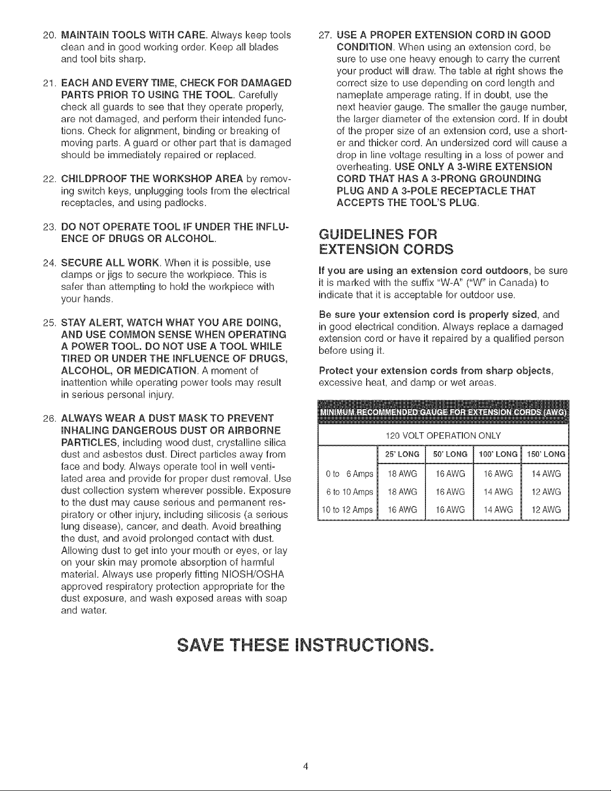
27, USE A PROPER EXTENSION CORD IN GOOD
CONDITION. When using an extension cord, be
sure to use one heavy enough to carry the current
your product will draw. The table at right shows the
correct size to use depending on cord length and
nameplate amperage rating, if in doubt, use the
next heavier gauge, The smaller the gauge number,
the larger diameter of the extension cord, if in doubt
of the proper size of an extension cord, use a short-
er and thicker cord, An undersized cord will cause a
drop in line voltage resulting in a loss of power and
overheating. USE ONLY A 3-WIRE EXTENSION
CORD THAT HAS A 3-PRONG GROUNDING
PLUG AND A 3-POLE RECEPTACLE THAT
ACCEPTS THE TOOL'S PLUG.
23. DO NOT OPERATE TOOL IF UNDER THE INFLU-
ENCE OF DRUGS OR ALCOHOL.
24, SECURE ALL WORK, When it is possibb, use
damps or jigs to secure the workpbce, This is
safer than attempting to hoUdthe workpbce with
your hands,
25. STAY ALERT, WATCH WHAT YOU ARE DOING,
AND USE COMMON SENSE WHEN OPERATING
A POWER TOOL. DO NOT USE A TOOL WHILE
TIRED OR UNDER THE INFLUENCE OF DRUGS,
ALCOHOL, OR MEDICATION. A moment of
inattention while operating power tools may result
in serious personal injury,
26, ALWAYS WEAR A DUST MASK TO PREVENT
INHALING DANGEROUS DUST OR AIRBORNE
PARTICLES, including wood dust, crystalline silica
dust and asbestos dust. Direct particles away from
face and body. Always operate tool in well venti-
lated area and provide for proper dust removal. Use
dust collection system wherever possible. Exposure
to the dust may cause serious and permanent res-
piratory or other injury, including silicosis (a serious
lung disease), cancer, and death. Avoid breathing
the dust, and avoid prolonged contact with dust.
Allowing dust to get into your mouth or eyes, or lay
on your skin may promote absorption of harmful
material. Always use properly fitting NIOSH/OSHA
approved respiratory protection appropriate for the
dust exposure, and wash exposed areas with soap
and water,
GUJDEUNES FOR
EXTENSION CORDS
If you are using an extension cord outdoors, be sure
it is marked with the suffix "W-A" CW" in Canada) to
indicate that it is acceptable for outdoor use,
Be sure your extension cord is properly sized, and
in good electrical condition, Always replace a damaged
extension cord or have it repaired by a qualified person
before using it,
Protect your extension cords from sharp objects,
excessive heat, and damp or wet areas.
120 VOLT OPERATION ONLY
25'LONG 50' LONG 100' LONG 150'LONG
0to 6Amps 18AWG 16AWG 16AWG 14AWG
6to 10Amps 18AWG 16AWG 14AWG 12AWG
10to 12Amps 16AWG 16AWG 14AWG 12AWG
SAVE THESE INSTRUCTIONS.
THIS TOOL MUST BE GROUNDED WHILE iN USE
TO PROTECT THE OPERATOR FROM ELECTRIC
SHOCK.
mNTHE EVENT OF A MALFUNCTION OR BREAK-
DOWN, grounding provides the path of bast resistance
for eUectriccurrent and reduces the risk of eUectric
shock, This tooUis equipped with an eUectric cord that
has an equipment grounding conductor and a ground-
ing pUug,The pUugMUST be pUugged into a matching
eUectdcaUreceptacb that is properUy installed and ground-
ed in accordance with ALL bcaU codes and ordinances,
DO NOT MODIFY THE PLUG PROVIDED, if it wHUnot
fit the eUectricaUreceptacb, have the proper eUectrbaU
receptacle installed by a qualified electrician,
USE ONLY A 3-WIRE EXTENSION CORD THAT HAS
A 3-PRONG GROUNDING PLUG AND A 3-POLE
RECEPTACLE THAT ACCEPTS THE TOOL'S PLUG.
REPLACE A DAMAGED OR WORN CORD IMMED-
iATELY.
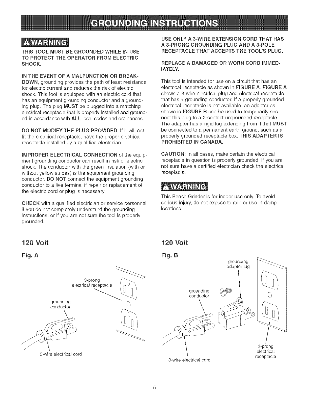
This tool is intended for use on a circuit that has an
electrical receptacle as shown in FIGURE A, FIGURE A
shows a 3-wire electrical plug and electrical receptacle
that has a grounding conductor, if a properly grounded
electrical receptacle is not available, an adapter as
shown in FIGURE B can be used to temporarily con-
nect this plug to a 2-contact ungrounded receptacle,
The adapter has a rigid lug extending from it that MUST
be connected to a permanent earth ground, such as a
properly grounded receptacle box, THIS ADAPTER iS
PROHIBITED IN CANADA.
iMPROPER ELECTRICAL CONNECTION of the equip-
ment grounding conductor can result in risk of electric
shock, The conductor with the green insulation (with or
without yellow stripes) is the equipment grounding
conductor, DO NOT connect the equipment grounding
conductor to a live terminal if repair or replacement of
the electric cord or plug is necessary,
CHECK with a qualified electrician or service personnel
if you do not completely understand the grounding
instructions, or if you are not sure the tool is properly
grounded,
120 Volt
Fig. A
3-prong
electricatreceptacle
grounding
conductor
CAUTION: in all cases, make certain the electrical
receptacle in question is properly grounded, if you are
not sure have a certified electrician check the electrical
receptacle,
This Bench Grinder is for indoor use only, To avoid
serious injury, do not expose to rain or use in damp
locations,
120 Volt
Fig. B
grounding
adapter lug
grounding
conductor
3-wire ebctricaI cord
3-wire electricaI cord
2-prong
ebctrica!
receptacle

SPECiFiC SAFETY JNSTFIUCTJONS
FOR BENCH GRINDERS
The operation of any grinder can result in debris being
thrown into your eyes, which can result in severe eye
damage, ALWAYS wear Safety Goggles (that comply
with ANSi standard Z87,1) when operating the grinder,
Safety Goggles are available at Sears Retail Stores,
Keep your thumbs and fingers away from the grinding
wheels,
1,
ALWAYS USE THE EYE SHIELDS AND WHEEL
GUARDS provided with the grinder,
2,
REPLACE A CRACKED OR DAMAGED GRiND-
iNG WHEEL iMMEDiATELY, A damaged wheel can
discharge debris at a high velocity towards the
operator, Carefully handle the grinding wheels since
they are abrasive, Prior to replacing a grinding
wheel, check it for cracks, DO NOT remove the
blotter or label on both sides of the grinding wheel,
Tighten the spindle nut just enough to hold the
grinding wheel firmly to the Bench Grinder, Do not
over-tighten the nut, Excessive damping force can
damage the grinding wheel, Only use the wheel
flanges provided with the grinder, When selecting a
replacement grinding wheel, verify that the grinding
wheel has a higher R,P,M, rating than the maximum
R,RM, of the Bench Grinder,
3, THE DIAMETER OF THE GRiNDiNG WHEELS
WILL DECREASE WITH USE, Adjust the tool rests
and spark arrestors to maintain a distance of 1/16"
from the wheel,
4, DO NOT STAND iN FRONT OF THE BENCH
GRINDER WHEN STARTING iT, Stand to one side
of the Bench Grinder and turn it "ON", Wait at the
side for one minute until the grinder comes up to
full speed, There is always a possibility that debris
from a damaged grinding wheel may be discharged
towards the operator,
5, THE BENCH GRINDER WILL PRODUCE SPARKS
AND DEBRIS DURING GRINDING OPERATIONS,
Be sure that there are not any flammable materials
in the vicinity, Frequently clean grinding dust from
the back of the Bench Grinder,
6, NEVER FORCE THE WORKPIECE AGAINST A
GRINDING WHEEL, especially if the wheel is cold,
Apply the workpiece slowly, allowing the grinding
wheel an opportunity to warm up, This wiii minimize
the chance of wheel breakage, DO NOT grind using
the sides of the grinding wheels, DO NOT apply
coolant directly to the grinding wheel,
7, KEEP ALL WHEEL GUARDS IN PLACE. DO NOT
USE THE BENCH GRINDER WITH THE WHEEL
GUARDS REMOVED,
8, KEEP THE TOOL RESTS FIRMLY TIGHTENED,
9, ALWAYS USE THE SUPPLIED WHEEL DRESSER
TO RESURFACE THE FACE OF THE GRINDING
WHEEL,
10, ADDITIONAL INFORMATION regarding the safe and
proper operation of this product is available from:
@ Power Tool institute
1300 Summer Avenue
Cleveland, OH 44115-2851
www, powe rtoolinstitute,org
@ National Safety Council
1121 Spring Lake Drive
Itasca, IL 60143=3201
@ American National Standards institute
25 West 43rd Street, 4th Floor
New York, NY 10036
www, ansi,org
@ ANSi 01,1 Safety Requirements for
Woodworking Machines and the
U,S, Department of Labor regulations
www, osha,gov
11, SAVE THESE INSTRUCTIONS, Refer to them
frequently and use them to instruct others,
AVAILABLE ACCESSORIES
Visit your Sears Hardware Department or see the
Sears Power and Hand Tool Catalog for the following
accessories,
ITEM
Replacement grinding wheels
Wire and Buffing wheels
Spacers
Wheel dressers
Universal stand
STOCK NUMBER
See catalog or store
See catalog or store
See catalog or store
See catalog or store
See catalog or store
Sears may recommend other accessories not listed in
this manual,
See your nearest Sears Hardware Department or Sears
Power and Hand Tool Catalog for other accessories,
Do not use any accessory unless you have completely
read the Owner's Manual for that accessory,
Use only accessories recommended for this Bench
Grinder, Using other accessories may cause serious
injury and cause damage to the Bench Grinder,

Fig. C G H
E
C ...................................m
N
\
U
j K
L
$
UNPACKING AND CHECKING
CONTENTS (Fig. C)
This Bench Grinder will require a minimal amount of
assembly, A 12mm x lOmm open end wrench is
provided for mounting the Tool Rest Assemblies and
the Spark Arrestor Assemblies,
1, Remove parts from all of the cartons and lay them
on a clean work surface,
2, Remove any protective materials and coatings from
all of the parts and the bench grinder, The protec°
tive coatings can be removed by spraying WD°40
on them and wiping it off with a soft cloth, This may
need to be redone several times before all of the
protective coatings are removed completely,
CAUTION: DO NOT use acetone, gasoline or
lacquer thinner to remove any protective coatings
on your bench grinder,
3, Compare the items to Figure C; verify that all items
are accounted for before discarding the shipping
box, if there are any missing parts, call Customer
Helpline 1°800°897°7709,
To avoid serious injury, do not attempt to plug in the
power cord and turn "ON" the Bench Grinder if any
parts are missing, The Bench Grinder can only be
turned "ON" after all the parts have been obtained and
installed correctly,
The following items are to be provided in the shipping
box:
A, Grinder (not shown)
B, Eyeshield (2)
C, Carriage head screw M6 x 80mm (2)
D, Spacer (2)
E, Fiat Washer M6 (2)
R Eyeshield knob (2)
G, Wheel dresser
H, Hex head screw 5/16o18 x 1/2" (4)
I, Fiat washer 5/16" (4)
J, Spark arrestor, left
K, Spark arrestor, right
L, Fiat washer 1/4" (2)
M, Hex head screw 1/4o20 x 1/4" (2)
N, Tool rest support, left
O, Tool rest support, right
R Tool rest, right
Q, Drill bit sharpening plate
R, Tool rest knob (2)
S, Fiat washer 5/16" (2)
T, Tool rest, left
U, Special wrench

13
14
15
16
6
7
10
QUmCKCHANGE WHEEL COVER - Covers the
grinding wheeUs and provides quick access for
routine maintenance,
2, QUICK RELEASE KNOB - Remove knob to allow
the Quick Change Wheel Cover to be removed,
3, SPARK ARRESTOR - Prevents hot sparks and
debris from contacting the operator,
4, FLEXIBLE WORK LIGHT - Provides light to the
operator during set up or grinding operations,
5, WHEEL DRESSER - Used to eUeanand smooth
front surface of the grinding wheel
6, INNER WHEEL GUARD - Covers the grinding
wheeUsand protects against aecidentaU contact,
7, EYESHIELD - Protective Lexan see-thru shieUds to
prevent any Uoosedebris from contacting the operator,
8, GRINDING WHEEL 60 GRIT - Used to remove Hght
matedaUfrom workpieee,
9, TOOL RESTS - Used to support the workpiece that
is being ground, AdjustaHe to provide angUedsurface,
11
12
10, DRILL BIT SHARPENING PLATE - Used to sharp-
en twist ddH bits, ShouUdbe removed for reguUar
grinding operations,
11, TOOL REST ADJUSTABLE SUPPORTS - Lets the
operator position the tooUrest closer to the wheeUas
the wheeUdecreases in diameter due to wear,
12, ON-OFF SWITCH - Used to turn ON and turn OFF
the grinder,
13, GRINDING WHEEL 36 GRIT - Used to remove
heavy matedaUfrom workpiece,
14, GRINDING WHEEL IDENTIFICATION LABEL -
Provides information on wheel size, grit and maxi-
mum rpm, Must be left on to distribute the load of
tightening the lock nuts,
15, FLANGES - Used to secure the grinding wheels to
the grinder and distribute the load of the Lock Nuts,
16, ARBOR HEX NUT - Used to secure the grinding
wheels to the grinder,
17, SPACER (not shown) - Used to align the wire wheel
or buffing wheel into the center of the tool rest,
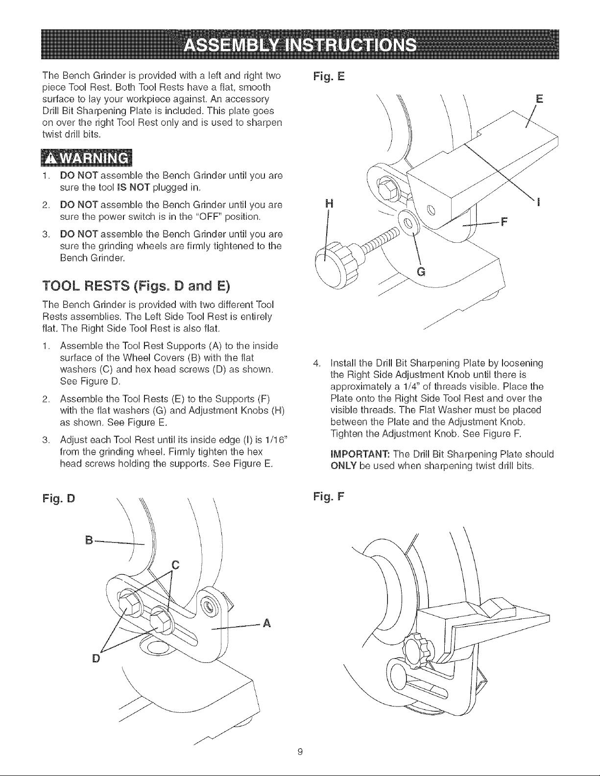
TheBenchGrinderisprovidedwitha bft andrighttwo
pieceTooURest,BothTooURestshaveafiat,smooth
surfacetoUayyourworkpbceagainst,Anaccessory
DrHUBitSharpeningHateisincluded,ThispUategoes
onovertherightTooURestonUyandisusedtosharpen
twistdrHUbits,
1, DONOTassembbtheBenchGrinderuntilyouare
surethetooUISNOTpUuggedin,
2, DONOTassembbtheBenchGrinderuntilyouare
surethepowerswitchisinthe"OFF"position,
3, DONOTassembbtheBenchGrinderuntilyouare
surethegrindingwheeUsarefirmUytightenedtothe
BenchGrinder,
TOOL RESTS (Figs. D and E}
The Bench Grinder is provided with two different Tool
Rests assemblies, The Left Side Tool Rest is entirely
flat, The Right Side Tool Rest is also flat,
1, Assemble the Tool Rest Supports (A) to the inside
surface of the Wheel Covers (B) with the flat
washers (C) and hex head screws (D) as shown,
See Figure D,
2, Assemble the Tool Rests (E) to the Supports (F)
with the flat washers (G) and Adjustment Knobs (H)
as shown, See Figure E,
3, Adjust each Tool Rest until its inside edge (I) is 1/16"
from the grinding wheel, Firmly tighten the hex
head screws holding the supports, See Figure E,
Fig. E
H
G
4,
Install the Drill Bit Sharpening Hate by loosening
the Right Side Adjustment Knob until there is
approximately a 1/4" of threads visible, Place the
Hate onto the Right Side Tool Rest and over the
visible threads, The Fiat Washer must be placed
between the Hate and the Adjustment Knob,
Tighten the Adjustment Knob, See Figure F,
IMPORTANT: The Drill Bit Sharpening Hate should
ONLY be used when sharpening twist drill bits,
E
Fig. D
Fig. F
C
D
9

SPARK ARRESTORS (Fig. G}
WORK UGHT (Fig. J}
Assembb the Spark Arrestors (A) to the inside
surface of the WheeU Covers (B) with the flat
washers (C) and hex head screws (D) as shown,
See Figure G,
2, Adjust each Spark Arrestor until the lower edge (E)
is 1/16" from the grinding wheel, Firmly tighten the
hex head screws, Bee Figure G,
Fig. G
The Bench Grinder is provided with a Fbxibb Work
Light to assist in visibility of the workpbce,
The Bench Grinder is NOT provided with a Hght buUbfor
the Fbxibb Work Light,
To reduce the risk of fire, use a 120 volt, 40 VVattor less
Track Light Bulb, Type R20, medium base or equivalent
(not included), DO NOT use a light bulb that extends
past the end of the light housing,
The Flexible Work Light may be turned "ON" or "OFF"
by using the rotary switch (B) on the top surface of the
housing (A), The switch can be rotated in the clockwise
direction only, See Figure J,
NOTE: The Flexible Work Light can be turned "ON" or
"OFF" even if the Bench Grinder is turned "OFF",
CAUTION: The Flexible Work Light housing wiii remain
hot for a few minutes after turning it "OFF", Avoid con-
tact with housing until it is cool,
EYESHJELDS (Fig. H}
Assemble the eyeshield (C) to the Spark Arrestor
(A) inserting carriage head screw (B) through
Eyeshield, the Spark Arrestor, and the Spacer (D)
as shown, Bee Figure H,
2,
Assemble the fiat washer (E) and Lock Knob (F)
to the carriage head screw and tighten until the
Eyeshield remains in the desired position,
See Figure H,
B
A
10
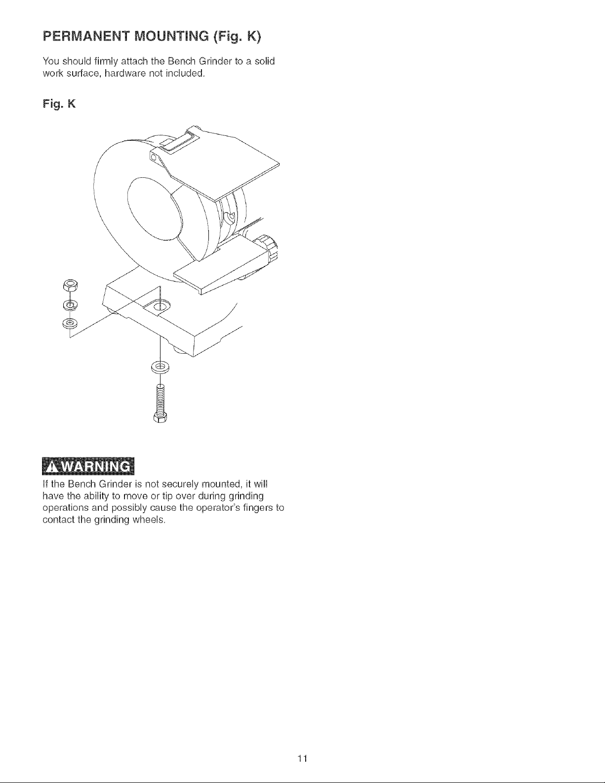
PERMANENT MOUNTING (Fig. K)
You shouUdfirmUyattach the Bench Grinder to a solid
work surface, hardware not included,
Fig. K
Ufthe Bench Grinder is not secureUy mounted, it wHU
have the ability to move or tip over during grinding
operations and possiMy cause the operator's fingers to
contact the grinding wheeUs,
11
 Loading...