

Page 1
Operator's Manual
durable, affordable, everyday tools.
3 Gallon Oil-free Compressor
with Brad nailer
and inflation/blowgun kit
item 15206
CAUTION: Read the Safety Guidelines
and All Instructions Carefully Before
Operating.
Sears, Roebuck and Co., Hoffman Estates, IL 60179 U.S.A.
Visit our Craftsman website: www.sears.com/craftsman
N032601 Rev.o o7/29/o9
Page 2
WARRANTY ................................................ 2
SPECIFICATION CHART ...................................... 3
SAFETY GUiDELiNES =DEFiNiTiONS ........................... 3
iMPORTANT SAFETY iNSTRUCTiONS ........................ 3-8
GLOSSARY ................................................ 9
ACCESSORIES ............................................. 9
DUTY CYCLE .............................................. 9
ASSEMBLY ............................................... 10
iNSTALLATiON ......................................... 11-12
OPERATION ............................................ 12-14
TROUBLESHOOTING .................................... 15-17
PARTS DIAGRAM/PARTS LIST. ........................... 18-19
CRAFTSMAN EVOLV FULL WARRANTY
Ifthis Craftsman Evolv compressor, nailer or accessories fail due to a defect in
material or workmanship within one year from the date of purchase, return it to
any Sears store or other Craftsman Evolv outlet in the United States for free
replacement.This warranty does not cover expendable parts such as o-rings or
driver blades that can wear out from normal use within the warranty period.
This warranty is void on each product if it is ever used for commercial or rental
purposes.
This warranty gives you specific legal rights, and you may also have other rights
which vary from state to state.
Sears, Roebuck and Co,, Hoffman Estates, IL 60179
2 - ENG
Page 3
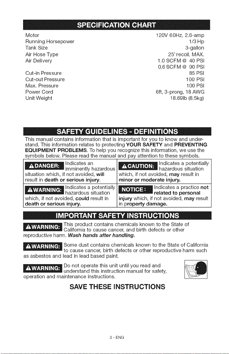
Motor 120V 60Hz, 2.6-amp
Running Horsepower 1/3 Hp
Tank Size 3-gallon
Air Hose Type 25' recoil, MAX.
Air Delivery 1.0 SCFM @ 40 PSi
0.6SCFM @ 90 PSI
Cut-in Pressure 85 PSI
Cut-out Pressure 100 PSI
Max. Pressure 100 PSI
Power Cord 6ft, 3-prong, 18 AWG
Unit Weight 18.691b (8.5kg)
This manual contains information that is important for you to know and under-
stand. This information relates to protecting YOUR SAFETY and PREVENTING
EQUIPMENT PROBLEMS. To help you recognize this information, we use the
symbols below. Please read the manual and pay attention to these symbols.
Indicates an _ hazardous situation
situation which, if not avoided, will which, if not avoided, may result in
result in death or serious injury, minor or moderate injury.
" _ - - related to personal
which, if not avoided, could result in injury which, if not avoided, may result
death or serious injury, in property damage.
imminently hazardous
Indicates a
hazardous situation
potentially Indicates a practice not
Indicates a potentially
This product contains chemicals known to the State of
California to cause cancer, and birth defects or other
reproductive harm. Wash hands after handling.
Some dust contains chemicals known to the State of California
to cause cancer, birth defects or other reproductive harm such
as asbestos and lead in lead based paint.
Do not operate this unit until you read and _AI
""__ understand this instruction manual for safety,
operation and maintenance instructions.
SAVE THESE INSTRUCTIONS
3 - ENG
Page 4
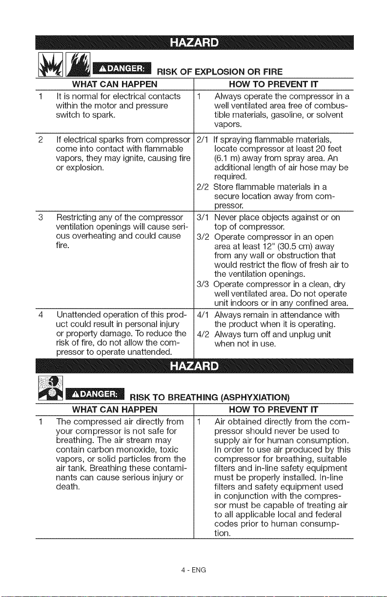
'" " RISK OF EXPLOSION OR FiRE
WHAT CAN HAPPEN HOW TO PREVENT iT
1 It is normal for electrical contacts 1 Always operate the compressor in a
within the motor and pressure well ventilated area free of combus-
switch to spark, tible materials, gasoline, or solvent
vapors.
2 2/1
If electrical sparks from compressor
come into contact with flammable
vapors, they may ignite, causing fire
or explosion.
If spraying flammable materials,
locate compressor at least 20 feet
(6.1 m) away from spray area. An
additional length of air hose may be
required.
2/2 Store flammable materials in a
secure location away from com-
pressor.
Restricting any of the compressor
ventilation openings will cause seri-
ous overheating and could cause
fire.
3/1 Never place objects against or on
top of compressor.
3/2 Operate compressor in an open
area at least 12" (30.5 cm) away
from any wall or obstruction that
would restrict the flow of fresh air to
the ventilation openings.
3/3 Operate compressor in a clean, dry
well ventilated area. Do not operate
unit indoors or in any confined area.
4 Unattended operation of this prod-
uct could result in personal injury
or property damage. To reduce the
risk of fire, do not allow the com-
4/1 Always remain in attendance with
the product when it is operating.
4/2 Always turn off and unplug unit
when not in use.
pressor to operate unattended.
__ RiSK TO BREATHING (ASPHYXiATiON)
WHAT CAN HAPPEN HOW TO PREVENT iT
The compressed air directly from
your compressor is not safe for
breathing. The air stream may
contain carbon monoxide, toxic
vapors, or solid particles from the
air tank. Breathing these contami-
nants can cause serious injury or
death.
Air obtained directly from the com-
pressor should never be used to
supply air for human consumption.
In order to use air produced by this
compressor for breathing, suitable
filters and in-line safety equipment
must be properly installed. In-line
filters and safety equipment used
in conjunction with the compres-
sor must be capable of treating air
to all applicable local and federal
codes prior to human consump-
tion.
4 - ENG
Page 5
Exposure to chemicals in dust cre-
ated by power sanding, sawing,
grinding, drilling, and other con-
struction activities may be harmful.
Sprayed materials such as paint,
paint solvents, paint remover, insec-
ticides, weed killers, may contain
harmful vapors and poisons.
2 Work in an area with good cross
ventilation. Read and follow the
safety instructions provided on the
label or safety data sheets for the
materials you are spraying. Always
use certified safety equipment:
NIOSH/OSHA respiratory protec-
tion or properly fitting face mask
designed for use with your specific
application.
_ I__ RISK OF BURSTING
Air Tank: On February 26, 2002, the U.S. Consumer Product Safety Commission
published Release # 02-108 concerning air compressor tank safety:
Air compressor receiver tanks do not have an infinite life. Tank life is dependent
upon several factors, some of which include operating conditions, ambient con-
ditions, proper installations, field modifications, and the level of maintenance.
The exact effect of these factors on air receiver life is difficult to predict.
If proper maintenance procedures are not followed, internal corrosion to the
inner wall of the air receiver tank can cause the air tank to unexpectedly rupture
allowing pressurized air to suddenly and forcefully escape, posing risk of injury
to consumers.
Your compressor air tank must be removed from service by the end of the year
shown on your tank warning label.
The following conditions could lead to a weakening of the air tank, and result in
a violent air tank explosion:
WHAT CAN HAPPEN
1 Failure to properly drain condensed
water from air tank, causing rust
and thinning of the steel air tank.
HOW TO PREVENT IT
Drain air tank daily or after each
use. If air tank develops a leak,
replace it immediately with a
new air tank or replace the entire
cornpressor.
Modifications or attempted repairs
to the air tank.
Never drill into, weld, or make any
modifications to the air tank or its
attachments. Never attempt to
repair a damaged or leaking air
tank. Replace with a new air tank.
Unauthorized modifications to
the safety valve or any other
components which control air tank
pressure.
3
The air tank is designed to
withstand specific operating
pressures. Never make adjustments
or parts substitutions to alter the
factory set operating pressures.
5 - ENG
Page 6
Attachments & accessories:
Exceeding the pressure rating of
air tools, spray guns, air operated
accessories, tires, and other
inflatables can cause them to
explode or fly apart, and could
result in serious injury.
Follow the equipment
manufacturers recommendation
and never exceed the maximum
allowable pressure rating of
attachments. Never use compressor
to inflate small low pressure objects
such as children's toys, footballs,
basketballs, etc.
Tires:
1 Over inflation of tires could result in 1 Use a tire pressure gauge to check
serious injuryand property damage, the tires pressure before each use
and while inflating tires; see the tire
sidewall for the correct tire pressure.
NOTE: Air tanks, compressors and
similar equipment used to inflate tires
can fill small tires very rapidly. Adjust
}ressure regulator on air supply to
no more than the rating of the tire
}ressure. Add air in small increments
and frequently use the tire gauge to
}revent over inflation.
[__ RISK OF ELECTRICAL SHOCK
WHAT CAN HAPPEN HOW TO PREVENT IT
Your air compressor is powered by
electricity. Like any other electrically
powered device, If it is not used
properly it may cause electric
shock.
Repairs attempted by unqualified
personnel can result in serious
injury or death by electrocution.
Electrical Grounding: Failure to
provide adequate grounding to
this product could result inserious
injury or death from electrocution.
Refer to Grounding Instructions
paragraph in the Installation
section.
1/1 Never operate the compressor
outdoors when it is raining or in wet
conditions.
1/2 Never operate compressor with
protective covers removed or
damaged.
2 Any electrical wiring or repairs
required on this product should be
performed by authorized service
center personnel in accordance with
national and local electrical codes.
3 Make certain that the electrical
circuit to which the compressor
is connected provides proper
electrical grounding, correct voltage
and adequate fuse protection.
6 - ENG
Page 7
__ RiSK FROM FLYING OBJECTS
WHAT CAN HAPPEN
1
The compressed air stream can
cause soft tissue damage to
exposed skin and can propel dirt,
chips, loose particles, and small
objects at high speed, resulting in
property damage or personal injury.
1/1 Always wear certified safety equip-
1/2 Never point any nozzle or sprayer
1/3 Always turn the compressor off
HOW TO PREVENT IT
ment: ANSI Z87.1 eye protection
(CAN/CSA Z94.3) with side shields
when using the compressor.
toward any part of the body or at
other people or animals.
and bleed pressure from the air
hose and air tank before attempt-
ing maintenance, attaching tools or
accessories.
RiSKOFHOTSURFACES
WHAT CAN HAPPEN HOW TO PREVENT IT
1 1/1 Never touch any exposed metal
Touching exposed metal such as
the compressor head, engine head,
engine exhaust or outlet tubes, can
result in serious burns.
parts on compressor during or
immediately after operation.
Compressor will remain hot for
several minutes after operation.
1/2 Do not reach around protective
shrouds or attempt maintenance
until unit has been allowed to cool.
_r_ __ R,SK FROM MOV,NG PARTS
WHAT CAN HAPPEN HOW TO PREVENT IT
1 Moving parts such as the pulley, fly- 1/1
wheel, and belt can cause serious
injury if they come into contact with
you or your clothing. 1/2
Attempting to operate compressor 2
with damaged or missing parts or
attempting to repair compressor
with protective shrouds removed
can expose you to moving parts
and can result in serious injury.
7 - ENG
Never operate the compressor with
guards or covers which are dam-
aged or removed.
Keep your hair, clothing, and gloves
away from moving parts. Loose
clothes, jewelry, or long hair can be
caught in moving parts.
1/3
Air vents may cover moving parts
and should be avoided as well.
Any repairs required on this product
should be performed by authorized
service center personnel.
Page 8
[__ RiSK OF UNSAFE OPERATION
WHAT CAN HAPPEN HOW TO PREVENT iT
1 Unsafe operation of your air com- 1 Review and understand all instruc-
pressor could lead to serious injury tions and warnings in this manual.
or death to you or others. 2 Become familiar with the operation
and controls of the air compressor.
3 Keep operating area clear of all per-
sons, pets, and obstacles.
4 Keep children away from the air
compressor at all times.
5 Do not operate the product when
fatigued or under the influence of
alcohol or drugs. Stay alert at all
times.
6 Never defeat the safety features of
this product.
7 Equip area of operation with a fire
extinguisher.
8 Do not operate machine with miss-
ing, broken, or unauthorized parts.
RiskOFFALLING
WHAT CAN HAPPEN HOW TO PREVENT IT
A portable compressor can fall
1 1 Always operate compressor in a
from a table, workbench, or roof
causing damage to the compres-
sor and could result in serious
injury or death to the operator.
stable secure position to prevent
accidental movement of the unit.
Never operate compressor on a
roof or other elevated position.
Use additional air hose to reach
high locations.
_ m D
,,L-'_,_= - ' RiSK FROM NOISE
WHAT CAN HAPPEN HOW TO PREVENT IT
Under some conditions and dura- 1 Always wear certified safety equip-
tion of use, noise from this product ment: ANSI S12.6 (S3.19) hearing
may contribute to hearing loss. protection.
SAVE THESE INSTRUCTIONS
FOR FUTURE USE
8 - ENG
Page 9
Become familiar with these terms
before operating the unit.
CFM: Cubic feet per minute.
SCFM: Standard cubic feet per min-
ute; a unit of measure of air delivery.
PSI: Pounds per square inch gauge;
a unit of measure pressure.
Code Certification: Products that
bear one or more of the following
marks: UL_>*,CUL, ETL_*>*,CETL, have
been evaluated by OSHA certified
independent safety laboratories and
meet the applicable Standards for
Safety.
*UL_ is a registered trademark of
Underwriters Laboratories and ETL®
is a registered trademark of Electrical
Testing Laboratories.
Cut-In Pressure: While the motor
is off, air tank pressure drops as you
continue to use your accessory. When
the tank pressure drops to a certain
low level the motor will restart auto-
matically. The low pressure at which
the motor automatically restarts is
called "cut-in" pressure.
Cut-Out Pressure: When an air com-
pressor is turned on and begins to
run, air pressure in the air tank begins
to build. It builds to a certain high
pressure before the motor automati-
cally shuts off, protecting your air tank
from pressure higher than its capacity.
The high pressure at which the motor
shuts off is called "cut-out" pressure.
Branch Circuit: Circuit carrying elec-
tricity from electrical panel to outlet.
Includes: brad nailer, nails, 25' recoil 1/4" male quick-connect plugs, PTEE-
air hose, inflation needle, tapered blow thead seal tape, I/4" female quick-
gun nozzle, blow gun adapter, blow connect body, hex wrench(2) and oil.
gun safety nozzle, blow gun, tire chuck,
This air compressor pump is capable average duty cycle be maintained;
of running continuously. However, to that is, the air compressor pump
prolong the life of your air compressor, should not run more than 30-45
it is recommended that a 50%-75% minutes in any given hour.
9 - ENG
Page 10
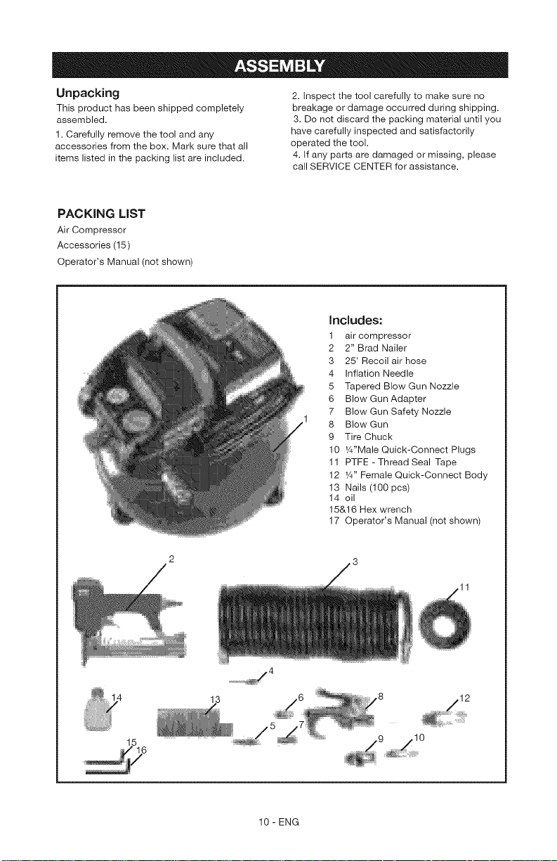
Unpacking
This product has been shipped completely
assembled.
1. Carefully remove the tool and any
accessories from the box. Mark sure that all
items listed in the packing list are included.
PACKING LiST
Air Compressor
Accessories (15)
Operator's Manual (not shown)
2. Inspect the tool carefully to make sure no
breakage or damage occurred during shipping.
3. Do not discard the packing material until you
have carefully inspected and satisfactorily
operated the tool.
4. If any parts are damaged or missing, please
call SERVICE CENTER for assistance.
[ncJudes:
1 air compressor
2 2" Brad Nailer
3 25' Recoil air hose
4 Inflation Needle
5 Tapered Blow Gun Nozzle
6 Blow Gun Adapter
7 Blow Gun Safety Nozzle
8 Blow Gun
9 Tire Chuck
10 W'Male Quick-Connect Plugs
11 PTFE - Thread Seal Tape
12 1¼,,Female Quick-Connect Body
13 Nails (100 pcs)
14 oil
15&16 Hex wrench
17 Operator's Manual (not shown)
10 - ENG
08
Page 11
HOW TO SET UP YOUR UNIT 3. Inspect the plug and cord before
Location of the Air Compressor
1. Locate the air compressor in a
clean, dry and well ventilated
area.
2. The air compressor should be
located at least 12" (30.5 cm)
away from the wall or other
each use. Do not use if there are
signs of damage.
4.
If these grounding instructions are
not completely understood, or if in
doubt as to whether the compres-
sor is properly grounded, have the
installation checked by a qualified
electrician.
obstructions that will interfere
with the flow of air.
3. The air compressor pump and
shroud are designed to allow for
proper cooling. The ventilation
openings on the compressor are
necessary to maintain proper
operating temperature. Do not
place rags or other containers on
or near these openings.
GROUNDING INSTRUCTIONS
RISK OF
ELECTRICAL
SHOCK. in the event of a short
circuit, grounding reduces the risk
of shock by providing an escape
wire for the electric current, This
air compressor must be properly
grounded.
The portable air compressor is
equipped with a cord having a
grounding wire with an appropriate
grounding plug (see following
illustrations).
SHOCK. IMPROPER GROUNDING
CAN RESULT IN ELECTRICAL
SHOCK.
Do not modify the plug provided. If
it does not fit the available outlet, a
correct outlet should be installed by
a qualified electrician.
Repairs to the cord set or plug
MUST be made by a qualified elec-
trician.
Extension Cords
If an extension cord must be used, be
sure it is:
1. 3-wire a extension cord that has a
3-blade grounding plug,and a 3-slot
receptaclethat will accept the plug on
the product.
2. in good condition
3. no longer than 50 feet
4. 14 gauge (AVVG)or larger.(Wiresize
increasesas gauge numberdecreas-
es. 12AWG and 10AWG may also be
used. DO NOTUSE 16 OR 18 AWG.)
RISK OF
ELECTRICAL
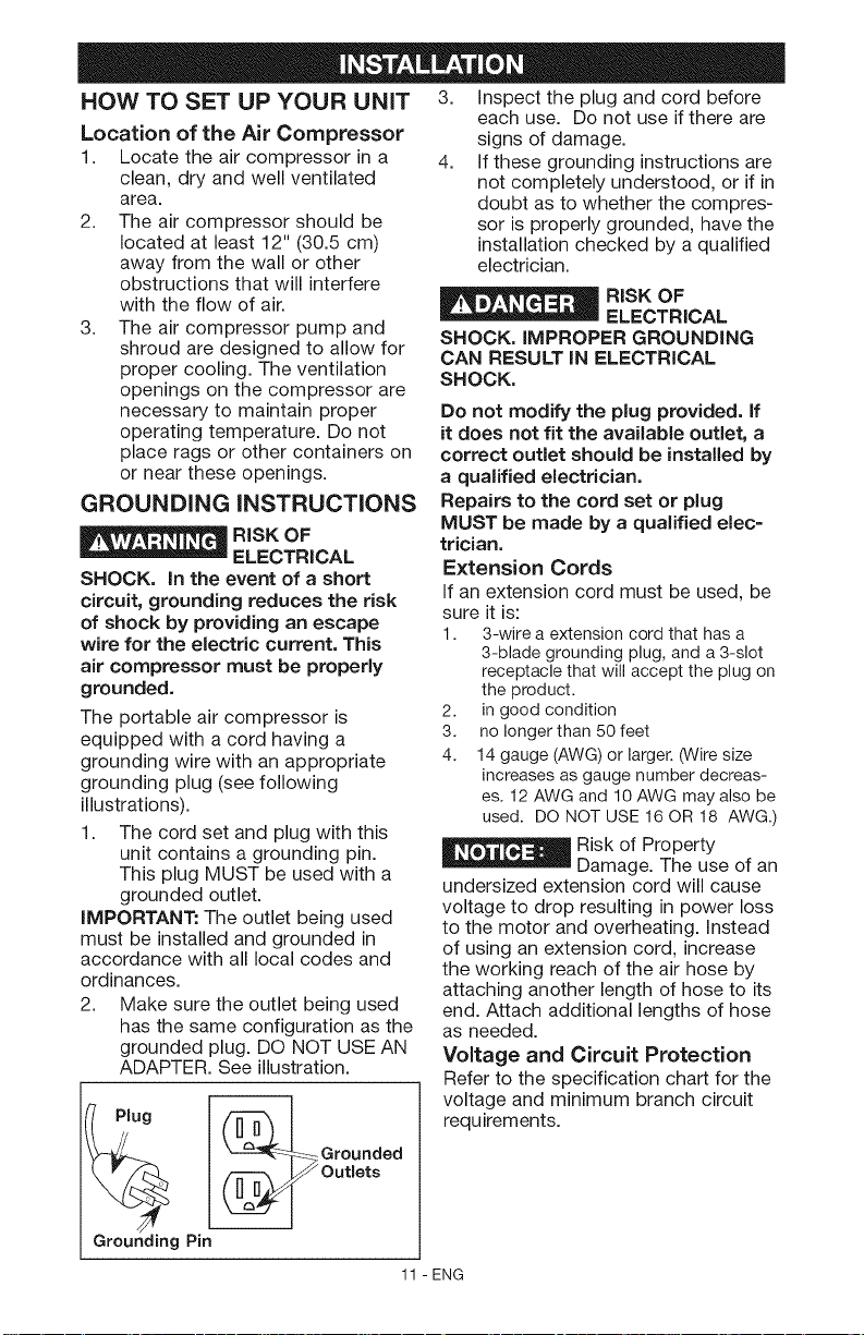
1. The cord set and plug with this
unit contains a grounding pin.
This plug MUST be used with a
grounded outlet.
IMPORTANT: The outlet being used
must be installed and grounded in
accordance with all local codes and
ordinances.
2. Make sure the outlet being used
has the same configuration as the
grounded plug. DO NOT USE AN
ADAPTER. See illustration.
_Risk of Property
Damage. The use of an
undersized extension cord will cause
voltage to drop resulting in power loss
to the motor and overheating. Instead
of using an extension cord, increase
the working reach of the air hose by
attaching another length of hose to its
end. Attach additional lengths of hose
as needed.
Voltage and Circuit Protection
Refer to the specification chart for the
voltage and minimum branch circuit
requirements.
Grounding Pin
_=-Grounded
I _Outlets
11 - ENG
Page 12
_Risk of unsafe operation. Certain air compressors can be
operated on a 15 amp circuit if the following conditions are met.
1. Voltage supply to circuit must comply
with the National Electrical Code.
2. Circuit must not be used to supply any
other electrical needs.
3. Extension cords must comply with
specifications.
circuit breaker or 15 amp time
delay fuse.
NOTE: if compressor is connected
to a circuit protected by fuses: use
only Time delay fuses should be
marked "D" in "Canada" and "T" in
the U.S.
4. Circuit is equipped with a 15 amp
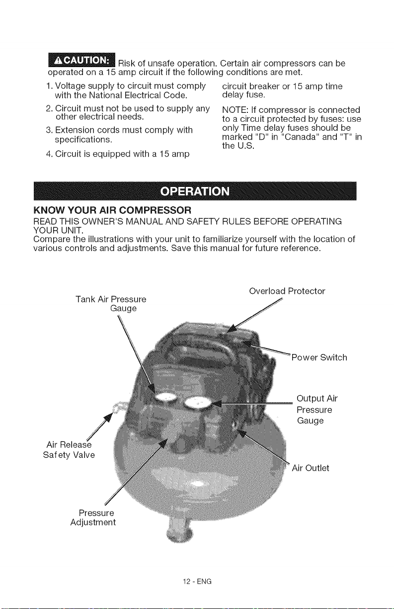
KNOW YOUR AiR COMPRESSOR
READ THiS OWNER'S MANUAL AND SAFETY RULES BEFORE OPERATING
YOUR UNIT.
Compare the illustrations with your unit to familiarize yourself with the location of
various controls and adjustments. Save this manual for future reference.
Tank Air Pressure
Air Release
Safety Valve
Pressure
Adjustment
Overload Protector
Gauge
Output Air
Pressure
Gauge
Outlet
12 - ENG
Page 13

OPERATING COMPRESSOR
TURNING COMPRESSOR ON
1. Pull and release the Air Release
Safety Valve to verify it does not stick.
2. Plug the power cord into a grounded
electrical outlet.
3. Press the Power Switch to the On
position.
4. Allow the Tank to fill to 85 PSi before
using. With the Air Compressor turned
on, operation is automatic and under
the control of the internal Pressure
Controller.
PRESSURE ADJUSTMENT
Set the appropriate air pressure output
for the air tool being used.
1. Turn the Pressure Adjustment knob
to the left to decrease output air
pressure, or to the right to increase the
output air pressure.
2. Read the air output pressure on the
Output Air Pressure Gauge.
USING THE A|R RELEASE
SAFETY VALVE
The Air Release Safety Valve isused
when tank decompression is needed
quickly and efficiently.
1. Press the Power Switch to the Off
position.
2. Pull on the Air Release Safety
Valve ring to release pressure
from the Tank.
3. When all pressure is released, let go
of the ring on the Air Release Safety Valve.
EMPTY AIR AND CONDENSATION
The water Drain Valve is located underneath
the Air Tank. It must be used daily to
release all trapped moisture through its valve.
It will also get rid of any condensation that
may cause tank corrosion.
_ Slightly open the water
Drain Valve to blow air and moisture
out of the Tank. Opening it all the way
may cause it to be blown off.
To help prevent tank corrosion and keep
moisture out of the air used, the air tank
of the compressor should be drained daily.
1. Turn the air compressor off, as shown in
the shut down section of the quick
reference label.
2. Pull the ring on the safety valve to
release until pressure gauge reads less
than 20 psi, as shown in the shut down
section of the quick reference label.
3. Release the ring.
4. Rotate drain valve counterclockwise
to open, as shown in the shut down
section of the quick reference label.
5. Tilt tank to drain moisture from
tank into a suitable container.
NOTE: Condensate is a polluting material
and should be disposed of in
compliance with local regulations. If drain
valve is clogged, release all air pressure,
remove and clean valve, then reinstall.
13 - ENG
Page 14

OPERATING BRAD NAILER
Always disconnect the tool from
the air supply before loading. When loading the
tool always aim the tool away from yourself and
others. Make sure that the trigger is not pressed
while the tool is being loaded.
1.Press the magazine release button and slide
open the magazine. (See Fig. F)
2.Insert a strip of fasteners. Strip should lay flat
against magazine wall with heads resting on
magazine ribbing and fastener points at bottom
of magazine. Strip should slide freely. (See Fig. G)
3.Push magazine closed and secure with release
button. (See Fig. H)
4. Connect the tool to the air supply. Make sure
the air supply is in the correct PSI range (see
Operating Instructions).
5. Contact surface of workplace with tip of
nailer. Depress the trigger to drive fastener into
the surface.
6. Test the driving depth in a sample piece
before using. If the fasteners are being driven
too deep, or not deep enough, adjust the
regulator to provide appropriate air pressure.
(See Fig. I)
7. Never operate the tool unless the tip of
the nailer is in contact with the workpiece. Do
not operate the tool without fasteners loaded
or damage to the tool may result.
Release
Bu_on
ig. F
Fig. H
Fig. I
Regulator
_ Disconnect the tool from the
air supply before performing any adjustments,
cleaning, maintenance, or repair.
1. Regular lubrication should be performed
if your tool is used without an in-line
automatic oiler. Place 2-6 drops of air tool
oil into the air inlet before each workday and
after every 2 hours of continuous use.
2. Check all connections and o-rings. Change
all worn or damaged o-rings, seals, etc.
Tighten all the screws and caps to prevent
potential damage or injury.
3. Inspect the trigger and safety mechanisms
to ensure they are working properly. Check
for loose or missing parts, binding, and/or
sticking parts and adjust or replace
accordingly.
4. Keep the nail magazine and the firing tip
of the tool clean and free of any foreign
particles or objects.
14 - ENG
Page 15

TROUBLESHOOT|NG OF COMPRESSOR
Failure
Compressor
will not run
Possible Cause
1. Loss of power or
overheating
2. No electrical power
Solution
1. Check for proper use of extension
cord
2. Plugged in? Check fuse/breaker or
motor overload
3. Blown fuse
4. Breaker open
5. Thermal overload open
6. Pressure switch bad
3. Replace blown fuse
4. Reset, determining why problem
happened
5. Motor will restart when cool; turn
off compressor and wait 20 minutes
6. Replace
Motor hums but
caRRot run or
runs slowly
Fuses blow/
circuit breaker
trips repeatedly
1. Low voltage
2. Wrong gauge wire or
length of extension cord
3. Shorted or open motor
winding
4. Defective check valve or
unloader
1. incorrect size fuse,
circuit overloaded
1. Check with voltmeter
2. Check gauge chart, under
Operation for proper gauge wire
and cord length
3. Replace motor
4. Replace or repair
1. Check for proper fuse, use time-
delay fuse. Disconnect other
electrical appliances from circuit or
operate compressor on its own
branch circuit
2. Wrong gauge wire or
length of extension cord
3. Defective check valve or
2. Check gauge chart, under
Operation
3. Replace or repair
under loader
Thermal
overload
}rotector cuts
out repeatedly
1. Low voltage
2. Clogged air filter
3. Lack of proper
ventilation/room
1. Check with voltmeter
2. Clean filter
3. Move compressor to well ventilated
area
temperature too high
Air receiver
)ressure drops
when
corn pressor
shuts off
4. Wrong gauge wire or
length of extension cord
1. Loose connections
(fittings, tubing, etc.)
2. Loose drain lock
3. Check valve leaking
4. Check gauge chart, under
Operation
1. Check all connections with soap
and water solution and tighten
2. Tighten
3. Disassemble check valve assembly,
clean or replace
, _,, , Do not disassemble
check valve with air
in tank;bleed tank
Excessive 1. Excessive water in air
1. Drain receiver
moisture in receiver
discharge air 2. High humidity 2. Move to area of less humidity; use
air line filter
Compressor . Defective pressure switch 1. Replace switch
runs 2. Excessive air usage 2. Decrease air usage; compressor
continuously not large enough for a requirement
3. Check valve leaking 3. Disassemble check valve assembly,
clean or replace
15 - ENG
Page 16

TROUBLESHOOTING OF COMPRESSOR
Failure Possible Cause Solution
Compressor Loose mounting bolts Tighten
vibrates
Air output lower 1. Broken inlet valves 1. Have authorized service
than normal 2. Intake filter dirty representative repair unit
3. Connections leaking 2. Clean or replace intake filter
3. Tighten connections
16 - ENG
Page 17

TROUBLESHOOTING OF BRAD NAILER
_lf any of the following
problems arise during operation, stop
using the tool immediately. Only a
qualified technician or service center
Disconnect the tool from the air supply
before any repair or adjustment. When
replacing O-rings or cylinders, lubricate
with air tool oil before reassembly.
can perform repairs on this tool.
Problem
Air leak near the
top of the tool or
inthe trigger area
Air leak near 1. Tighten screws.
bottom of tool. 2. Check and replace O-rings
Air leak between 1. 1.
body and 2. 2.
cylinder cap.
Fasteners being 1. 1.
driven too deep. 2. 2.
Tool does not
function well,
does not drive
fasteners,
operates
sluggishly.
Possible Causes
1.
O-ring in trigger valve
damaged.
2.
Trigger valve head
damaged.
3.
Trigger valve stem, seal,
or O-ring damaged.
Loose screws
Worn or damaged O-rings
or bumper.
Loose screws.
Worn or damaged O-rings
or seals.
Worn bumper.
Air pressure is too high.
1. 1.
Inadequate air supply.
2. 2.
Inadequate lubrication.
3. Worn or damaged O-rings
or seals.
4. Exhaust port in cylinder
head is blocked.
Probable Solutions
1.
Push Power Switch to
On position.
2.
Check power at outlet.
3.
Plug line cord into electrical
outlet.
1.
2.
and/or bumper.
Tighten screws.
Check and replace O-rings
or seals.
Replace bumper.
Adjust air pressure.
Verify adequate air supply.
Place 2-6 drops of oil into
air inlet to lubricate.
3.
Check and replace O-rings
or seals.
4.
Consult qualified service
technician to replace
internal parts.
Tool skips 1. Worn bumper or damaged 1. Replace bumper or loading
fasteners
loading spring.
2. Dirt in front plate.
3. Dirt or damage is
preventing fasteners from
moving, freely in the
spring.
2. Clean drive channel on
front plate.
3. Clean magazine.
magazine.
4. Worn or dried-out O-ring on
piston, or lack of lubrication.
5. Cylinder cover seal leaking.
4. O-ring needs to be replacec
or lubricated.
5. Replace sealing washer.
Tool jams
1. Incorrect or damaged
fasteners.
2. Damaged or worn driver
guide.
3. Magazine or nose screw
loose.
4. Magazine is dirty.
17 - ENG
1. Change and use correct
fasteners.
2. Check and replace the
driver guide.
3. Tighten the magazine.
4. Clean the magazine.
Page 18

Air Compressor item 15206
PARTS SHOWN FOR REFERENCE ONLY
_ jjjjT,
18 - ENG
Page 19

Air Compressor item 15206
Item Part No. Description
1 3290408 Flat Washer
2 3220552 Screw, M5x25
3 3410652 Handle
4 3220404 Screw, ST4.2x25
5 3410452 Tooling Cover
6 3630252 Overload, Protector
7 3630150 Power Switch
8 3111352 Electric Wire Assembly
9 3410352 Screw, ST4.2x25
10 3110252 Motor-pump Assembly
11 3110152 Circuit Board
12 3220840 Screw, M4x8
13 3640152 Power Cord
14 3220475 Screw, ST4.8x15
15 3410302- Wire Clip
16 3410552 Cover, Bottom
17 3030150 Tube
I 18 3410329 Zip Tie
19 3420652 Seal Ring
20 3290252 Spring
Qty Item Part No. Description
2 21 3410152 Ball
2 22 3420350 Damping Pad
1 23 3220150 Screw, M6xl 5
4 24 3220250 Screw, M6x25
1 25 3390250 Copper Tube 1
1 26 3290651 Washer 1
1 27 3020152 Copper hoop 2
1 28 3020252 Copper Connector knob 2
1 29 3630152-1 Pressure Controller 1
1 30 3220840 Screw, M4xl0 1/2
1 31 3410350 Fan 1
2 32 3290706 Flat washer 1
1 33 3220205 Screw, M4xl 0 1
1 34 3110752 Pressure Regulator Assembly 1
1 35 3330152-1 Tank, 3G 1
1 36 3290275 Drain Valve Assembly 1
18 37 3420150 Foot 3
1 38 3290750 Flat Washer 6
1 39 3220150 Screw, M6xl 5 3/6
1
Qty
1
4
6
4
19 - ENG
Page 20

Manual del Operador
durable, affordable, everyday tools.
Compresor Sin Aceite de 3 Galones
con Martillo de Clavos Peque_os y
Juego para Inflar/Pistola para Soplado
Articulo 15206
PRECAUCl0N: Antes de hacer funcionar
esta herramienta lea cuidadosamente los
lineamientos de seguridad y todas las instrucciones.
Sears, Roebuck and Co., Hoffman Estates, IL 60179 EE.UU.
Visite et sitio web de Craftsman en: www.sears.com/craftsman
N032601 Rev.o o7/29/o9
Page 21

GARANTIA .................................................... 21
CUADRO DE ESPECIFICACIONES .................................. 22
L|NEAMIENTOS DE SEGURIDAD, DEFINUCIONES ...................... 22
INSTRUCCIONES IMPORTANTES SOBRE SEGURIDAD ............... 22=27
GLOSARIO .................................................... 28
ACCESORIOS .................................................. 28
CICLO DE TRABAJO ............................................. 28
ENSAMBLAJE .................................................. 29
INSTALACI6N ............................................... 30=31
FUNC|ONAMIENTO ........................................... 31 =33
RESOLUCI6N DE AVERIAS ..................................... 34=36
DiAGRAMA DE P|EZAS, MSTA DE P|EZAS ......................... 37=38
GARANTfA COMPLETA PARA EVOLV DE CRAFTSMAN
Si dentro del a_o a partir de la fecha de compra este compresor, el martillo o
sus accesorios Evolv de Craftsman fallan debido a algQn defecto, ya sea en
material o mano de obra, devu61valo a cualquier almac6n de Sears o a
cualquier tienda de distribuci6n Evolv de Craftsman en Estados Unidos para
obtener un reemplazo sin costo alguno. Esta garantia no cubre piezas
consumibles tales como aros t6ricos o cuchillas de impulsi6n que pudieran
desgastarse debido al uso normal dentro del periodo de garantia. Esta
garantia se anula si el producto se usa alguna vez con prop6sitos comerciales
o para alquiler. Esta garantia le proporciona derechos legales especificos y
pudieran existir otros derechos, los cuales varian de un estado a otro.
Sears, Roebuck and Co,, Hoffman Estates, IL 60179
21 - SP
Page 22

Motor 120V 60Hz, 2.2 amp.
Caballos de fuerza de funcionamiento 1/3 Caballos
Tamar_o del tanque
Tipo de manguera para aire
Entrega de aire
Presi6n de corte de entrada
Presi6n de corte de salida
Presi6n m_.xima
Cord6n el6ctrico
Peso de la unidad
Este manual contiene informaci6n importante de saber y comprender. Esta
informaci6n se relaciona con la protecci6n de SU SEGURIDAD y con la
PREVENCION DE PROBLEMAS CON EL EQUIPO. Para ayudarle a reconocer tal
informaci6n, utilizamos los siguientes simbolos. Sirvase leer el manual y poner
atenci6n a esos simbolos.
1.0 pIES/MIN ESTANDAR A 40 LBS/PUL 2
0.6 PIESS/MIN EST_,NDAR A 90 LBS/PUL 2
25 pies MAX, replegable
6 pies, 3 espigas, 18 AWG
3 galones
85 LBS/PUL 2
100 LBS/PUL 2
100 LBS/PUL 2
8.5kg (18.691b)
_lndica situaciones _ Indica situaciones
peligrosas que, si no se evitan, resultan peligrosas que, si no se evitan, podrian
en la muerte o en lesiones serias, resultar en lesiones entre minimas y
_lndica situaciones _ Indica prficticas no
peligrosas que, si no se evitan, lesiones personales las cuales, si no se
podrian resultar en la muerte o en evitan, podr[an resultar endaSos a ta
lesiones serias propiedad,
nacimiento u otros dar_os al sistema reproductivo. Lavese tas manos tuego de
su manejo,
_ iertos aserrines, tales como los de asbestos y el plomo de
de acuerdo al Estado de California provocan c_.ncer, defectos de nacimiento u
otros dar_os al sistema reproductivo.
w ,= - , , Noopereestaunidadantesdeleery _
" '-"'__ comprender este manual de instrucciones en
cuanto al funcionamiento con seguridad y las instrucciones de
mantenimiento.
inminentemente ..... potencialmente
moderadas.
potencialmente relacionadas con
Este producto contiene sustancias quimicas que de acuerdo
al Estado de California provocan c_,ncer, defectos de
las pinturas con plomo, contienen productos quimicos que
GUARDE ESTAS INSTRUCCIONES
22 - SP
Page 23

RIESGO DE INCENDIO O EXPLOSION
QUE PODRIA SUCEDER COMO PREVENIRLO
1 Es normal que los contactos 1 Opere siempre el compresor en
el6ctricos dentro del motor y los lugares bien ventilados que est6n
interruptores de presi6n produzcan libres de materiales combustibles,
chispas, gasolina o vapores solventes.
2 2/1
Si las chispas el6ctricas del
compresor entran en contacto con
vapores inflamables, estos se
podrian encender, provocando
incendios o explosiones.
Siesta rociando materiales
inflamables, coloque el compresor
pot Io menos a 6.1 metros (20 pies)
del &tea de rociado. Podria ser
necesario contar con una manguera
adicional.
2/2 Almacene los materiales inflamables
en un lugar seguro lejos del
compresor.
Restringir cualquiera de las aperturas
para ventilaci6n del compresor
podria provocar sobrecalentamiento
grave y generar incendios.
3/1 Nunca coloque objetos contra el
compresor ni encima de 61.
3/20pere el compresor en &reas
abiertas por Io menos a una
distancia de 30.5 cm (12 pulgadas)
de cualquier pared u obstrucci6n
que pudiera restringir el flujo de
aire fresco hacia las aperturas para
ventilaci6n.
3/30pere el compresor en areas
limpias, secas y con buena
ventilaci6n. No opere la unidad en
interiores o en &teas confinadas.
4 Si este producto se deja funcionar
sin atenci6n se podrian provocar
lesiones personales o da_os a la
propiedad. Para reducir el riesgo de
incendios, no deje que el compresor
4/1 Debe haber siempre alguien
atendiendo el producto cuando est6
funcionando.
4/2 Apague la unidad y desenchQfela
cuando nadie la est6 usando.
funcione sin alguien que Ioatienda.
m q
RIESGO PARA LA RESPIRACtON (ASFIXlA)
QU¢= PODRIA SUCEDER
No es seguro respirar el aire
comprimido que sale directamente
del compresor. El chorro de aire
podria contener mon6xido de
carbono, vapores t6xicos y
particulas s61idas provenientes del
tanque de aire. Respirar tales
contaminantes podria provocar
lesiones serias o la muerte.
COMO PREVENIRLO
1 Nunca se debe usar aire que provenga
directamente del compresor para la
respiraci6n humana. Para poder usar
el aire que produce este compresor
para la respiraci6n, se debe instalar
apropiadamente filtros adecuados y
equipo de seguridad en linea. Antes
del consumo humano, los filtros y el
equipo de seguridad en linea
utilizados con el compresor deben
set capaces de modificar el aire
segM3ntodos los c6digos aplicables
locales y federales.
23 - ENG
Page 24

2 La exposici6n a los quimicos dentro
del polvo creado por los chorros de
arena, aserrado, esmerilado,
taladrado y otras actividades de la
construcci6n puede ser dafiina.
3 Los materiales que estan siendo
rociados tales como pintura,
solventes o disolventes de pintura,
insecticidas y eliminadores de malas
hierbas podrian contener vapores
peligrosos y veneno.
2 Trabaje en &reas con buena ventilaci6n
cruzada. Lea y obedezca las
instrucciones de seguridad que se
presentan en las vifietas o en las hojas
de seguridad de los materiales que est6
rociando. Use siempre equipo de
seguridad certificado: Protecci6n
respiratoria o caretas adecuadamente
ajustadas aprobadas por NIOSH/OSHA
y disefiadas para usarse en
aplicaciones especificas.
m e,
_ _l_J__ R|ESGO DE EXPLOSION
Tanques de aire: El26 de febrero de 2002, la Comisi6n de EE.UU. sobre
Seguridad de Productos para Consumidores (U.S. Consumer Product Safety
Commission) public6 la emisi6n # 02-108 relativa a la seguridad de tanques de
compresores de aire:
Los tanques receptores de compresores de aire no tienen una vida Qtil infinita. La
vida Qtil de los tanques depende de varios factores, entre ellos se incluyen las
condiciones de operaci6n, las condiciones ambientales, instalaciones apropiadas,
modificaciones de campo y el nivel de mantenimiento.
Es dificil predecir el efecto exacto de tales factores sobre la vida Qtil del receptor
de aire. Si no se observan procedimientos de mantenimiento adecuados, la
corrosi6n interna en las paredes interiores de los tanques receptores de aire
puede provocar que los tanques de aire se rompan inesperadamente, permitiendo
que el aire presurizado escape repentina y en6rgicamente, presentando riesgos
de lesiones a los consumidores.
Se debe remover de servicio el tanque de aire de su compresor al final del afio
que se muestra en la vifieta de advertencia del tanque. Las siguientes condiciones
podrian provocar el debilitamiento del tanque de aire y hacer que explote
violentamente.
QUE PODRIA SUCEDER
Dejar de drenar apropiadamente el
agua condensada del tanque de
aire, generando 6xido y
adelgazamiento del acero del
tanque de aire.
Modificaciones o intentos de
reparaciones al tanque de aire.
Modificaciones no autorizadas alas
valvulas de seguridad o a cualquier
otto componente que controla la
presi6n del tanque de aire.
COMO PREVENIRLO
Drene el tanque de aire diariamente o
despu6s de cada uso. Siaparece una
fuga en el tanque de aire, reempl&celo
inmediatamente con un tanque de
aire nuevo o reemplace todo el
compresor.
2 Nunca taladre, suelde o haga cualquier
modificaci6n al tanque de aire osus
accesorios. Nunca trate de reparar un
tanque de aire dafiado o con fugas.
Reempl&celo con un tanque de aire
nuevo.
3 El tanque de aire esta disefiado para
resistir presiones de operaci6n
especificas. Nunca ajuste ni substituya
las piezas para alterar la presi6n de
operaci6n ajustada en f&brica.
24 - SP
Page 25

Accesorios y utensilios:
1 Exceder la presi6n limite de las
herramientas neum&ticas, pistolas
de rociado, accesorios impulsados
pot aire, Ilantas y otros elementos
inflables podria hacer que exploten o
vuelen en pedazos y se provoquen
lesiones graves.
Siga las recomendaciones de los
fabricantes de los equipos y nunca
exceda la presi6n m&xima permitida
de los accesorios. Nunca use el
compresor para inflar objetos de baja
presi6n tales como juguetes para
ni_os, balones de f0tbol, de
b&squetbol, etc.
Mantas:
1 Inflardemasiado lasIlantas podda
provocar lesiones graves ydanos a la
propiedad, uso y al inflarlas; averigOe la presi6n
1 Utilice un calibrador paraverificar la
presi6n de las Ilantas antes de cada
correcta de las Ilantas en sus paredes
laterales.
NOTA: Los tanques de aire, compresores
y equipo similar que se usan para inflar
Ilantas pueden inflar r&pidamente las que
son pequedas. Ajuste el regulador de
}resi6n en el suministro de aire hasta un
limite de la presi6n m&xima permitida
}ara la Ilanta. Adada aire en pequedos
incrementos y use frecuentemente el
calibrador para evitar inflarlas demasiado.
_]_ RIESGO DE CHOQUES ELECTR|COS
QUE PODR{A SUCEDER
El compresor de aire funciona con
electricidad. Como cualquier otto
dispositivo el6ctrico, si no se le usa
apropiadamente se podrian
provocar choques el6ctricos.
1/1 Nunca use el compresor al aire libre
1/2 Nunca opere el compresor sin sus
COMO PREVENIRLO
cuando est6 Iloviendo ni cuando
existan condiciones h0medas.
cubiertas protectoras o si est&n
dadadas.
Las reparaciones intentadas pot
personal no calificado pueden
provocar lesiones graves o la
muerte por electrocuci6n.
2 Cualquier cableado o reparaci6n
el6ctrica que se deba efectuar en el
producto debe ser efectuada por
personal de un centro de servicio
autorizado de acuerdo a los c6digos
el6ctricos nacionales y locales.
Conexi6n el_ctrica a tierra: No
conectar este producto a tierra
podria provocar lesiones graves o la
muerte pot electrocuci6n. Vea el
p&rrafo referente a Instrucciones
3 AsegOrese de que el circuito el6ctrico
al que se ha de conectar el compresor
permite una conexi6n atierra apropiada,
voltaje correcto y protecci6n adecuada
mediante fusibles.
para conexi6n a tierra en la
secci6n de instalaci6n.
25 - SP
Page 26

__ RIESGO DE OBJETOSAEROTRANSPORTADOS
QUE PODRiA SUCEDER
El chorro de aire comprimido puede
provocar da_os al tejido suave de la
piel expuesta y puede propulsar a
gran velocidad suciedad, astillas,
particulas sueltas y objetos
peque_os provocando da_os a la
propiedad o lesiones personales.
1/1 Use siempre equipo de seguridad
1/2 compresor.
1/3 animales.
COMO PREVENIRLO
certificado: Protecci6n para los ojos
ANSI Z87.1 (CAN/CSA Z94.3) con
cubiertas laterales al usar el
Nunca apunte la boquilla ni el
rociador hacia cualquier parte de su
cuerpo o de otras personas o
Antes de intentar darle mantenimiento
o de colocar herramientas o
accesorios apague siempre el
compresor y sangre la presi6n de la
manguera y del tanque de aire.
, 0
__ RtESGO DEBIDO A SUPERFICIES CALIENTES
QUE PODRIA SUCEDER
Tocar metal expuesto tal como el
cabezal del compresor, el cabezal
del motor, el escape o los tubos
de salida podria resultar en
quemaduras graves.
COMO PREVENIRLO
1/1 Nunca toque las piezas met_licas
expuestas del compresor durante el
funcionamiento ni inmediatamente
despu6s. El compresor permanece
caliente durante varios minutos
1/2 despu6s del funcionamiento.
No trate de tocar dentro de las
cubiertas de protecci6n nitrate de
dar mantenimiento a la unidad antes
de permitir que se enfrie.
___ RIESGO DEBIDO A PIEZAS MOVILES
QUE PODRIA SUCEDER
Las piezas m6viles, tales como
poleas, volantes, y correas pueden
provocar lesiones graves si entran
en contacto con el cuerpo o la ropa.
COMO PREVENIRLO
1/1 Nunca haga funcionar el compresor
si se han da_ado o removido sus
protecciones o cubiertas.
1/2 Mantenga el cabello, ropa y guantes
alejados de las piezas m6viles. La
ropa o joyeria holgada y el cabello
largo podrian ser atrapados por las
piezas m6viles.
1/3 Tampoco se debe tocar los
respiraderos ya que podrian
encontrarse sobre piezas m6viles.
Intentar hacer funcionar el 2
compresor con piezas da_adas o
faltantes o tratar de repararlo sin sus
cubiertas de protecci6n puede
Todas las reparaciones que este
producto necesite deben ser efectuadas
por personal de centros autorizados
para servicio.
exponerlo alas piezas m6viles y
resultar en lesiones graves.
26 - SP
Page 27

[_ I__ RIESGO DEBtDO A FUNCIONAMIENTO INSEGURO
QUE PODRtA SUCEDER COMO PREVENIRLO
1 El funcionamiento insegurodel 1 Estudie y comprenda todas las
compresor de aire puede generar instrucciones y advertencias de este
lesiones graves o la muerte a usted manual.
u otras personas. 2 Familiaricese con el funcionamiento y
los controles del compresor de aire.
3 Mantenga el lugar de operaciones libre
de espectadores, mascotas y obst&culos.
4 Mantenga a los ni_os alejados del
compresor de aire en todo momento.
5 No haga funcionar el producto mientras
se encuentre fatigado o bajo la influencia
de alcohol o drogas. Mant6ngase alerta
en todo momento.
6 Nunca contravenga los sistemas de
seguridad de este producto.
7 Coloque un extintor de incendios en el
&rea de operaciones.
8 No haga funcionar la m&quina si le
hacen falta piezas o con piezas
quebradas o no autorizadas.
_ I__ RIESGO DEBIDO A OBJETOS QUE CAEN
QU¢_PODR[A SUCEDER COMO PREVENIRLO
1
Los compresores port&tiles podrian
caerse de mesas, bancos de
trabajo o techos provocando da_os
al compresor y podrian resultar en
lesiones graves o la muerte del
operador.
1 Para evitar el movimiento accidental
de la unidad, coloque siempre el
compresor en una posici6n segura y
estable. Nunca haga funcionar el
compresor sobre techos u otros
lugares altos. Utilice mangueras
adicionales para alcanzar los
lugares altos.
R 4
RIESGO DEBIDO A RUIDO
QU¢_ PODR[A SUCEDER C6MO PREVENIRLO
L#ea_econditions and dura- 1 Use siempre equipo de seguridad
tion of use, noise from this product certificado: Protecci6n para los oidos
may contribute to hearing loss. ANSI S12.6 (S3.19).
GUARDE ESTAS INSTRUCCIONES
PARA USARLAS EN EL FUTURO
27 - SP
Page 28

Familiaricese con los siguientes
t6rminos antes de hacer funcionar la
unidad.
PIESS/MIN (CFM pot sus siglas en
ingles): Pies cObicos pot minuto.
PtES3)IVIIN ESTANDAR (SCFM pot
sus siglas en ingles): Pies cL_bicos
pot minuto est&ndar; es una unidad
de medida de la entrega de aire.
LBS/PUL 2(PS| pot sus siglas en
ingles): Libras por pulgada cuadrada
manom6tricas; es una unidad de
presi6n
Certificaci6n pot c6digo: Los
productos que presentan una o m&s
de las siguientes mamas:
UL®*,CUL, ETL®*,CETL, han sido
evaluados por laboratorios
independientes sobre seguridad
certificados por OSHA y cumplen las
normas de seguridad aplicables.
*UL® es marca comercial registrada de
Underwriters Laboratories y ETL® es
marca comercial registrada de
Electrical Testing Laboratories.
Presi6n de corte de entrada: Mientras
el motor se encuentra apagado, la
presi6n del tanque se reduce cuando
se continua usando los accesorios.
Cuando la presi6n del tanque cae m&s
all& de cierto nivel el motor arranca de
nuevo autom&ticamente. A la presi6n
baja a laque el motor arranca de nuevo
autom&ticamente se le llama presi6n
"de corte de entrada".
Presi6n de corte de salida: Cuando
se enciende un compresor y
comienza a funcionar, la presi6n de
aire en el tanque comienza a
acumularse. Llega a cierta presi6n alta
antes de que el motor se apague
autom&ticamente, protegiendo el
tanque de aire contra presiones m&s
altas que su capacidad. A la presi6n
alta a la que el motor se apaga se le
llama presi6n "de corte de salida".
Circuito secundario: Un circuito que
Ileva electricidad desde el tablero
hacia el tomacorriente.
Incluye: Martillo de clavos pequedos,
clavos manguera de aire replegable
de 7.5 m (25 pies), aguja para inflar,
boquilla c6nica para pistola para
soplado, adaptador de pistola para
tapones machos de conexi6n r&pida
de 1¼de pulgada, cinta para sello de
roscas PTEE, carroceria hembra para
conexi6n r&pida de 1¼de pulgada, (2)
Ilaves hexagonales y aceite.
soplado, boquilla de seguridad de
pistola para soplado, pistola para
soplado, mandril para Ilantas,
La bomba del compresor de aire es es decir, la bomba del compresor de
capaz de funcionar continuamente, aire no debe funcionar m&s de 30 a 45
Sin embargo, para prolongar la vida minutos en cualquier hora.
_til de su compresor, se recomienda
mantener un ciclo de trabajo
promedio de entre 50 y 75%;
28 - SP
Page 29

Desempaquetado
Este producto se envia completamente
ensamblado.
1. Saque cuidadosamente la
herramienta y los accesorios de la caja.
AsegQrese de encontrar todos los
articulos mencionados en la lista de
empaque.
LiSTADO DE EMBALAJE
Compresor de aire
Accesorios (15)
Manual del operador (no se muestra)
2. Revise la herramienta
cuidadosamente para asegurarse de
que no se quebr6 o daft6 durante el
envio.
3. No deseche el material de empaque
antes de inspeccionar cuidadosamente
la herramienta y de hacerla funcionar
satisfactoriamente.
4. Si hay alguna pieza daffada o faltante,
sirvase Ilamar al CENTRO DE SERVICIO
para obtener ayuda.
Inciuye:
1 Compresor de aire
2 Martillo de clavos pequeSos
de 2 pulgadas
3 Manguera de aire replegable
de 7.5 m (25 pies)
4 Aguja para inflar
5 Boquilla c6nica para pistola
para soplado
6 Adaptador de pistola para soplado
7 Boquilla de seguridad de pistola
para soplado
8 Pistola para soplado
9 Mandril para Ilantas
10 Tapones macho de conexi6n
r&pida de 1Ade pulgada
11 Cinta para sellar roscas PTFE
12 Carroceria hembra de conexi6n
r&pida de 1Ade pulgada
13 Clavos (100 piezas)
14 aceite
15 y 16 Llaves hexagonales
17 Manual del operador (no se muestra)
29 - ENG
Page 30

COMO ACOPLAR SU UNIDAD
Ubicaci6n det compresor de aire
1. Coloque el compresor de aire en
un b.rea limpia, seca y con buena
ventilaci6n.
2. Se debe colocar el compresor de
aire por Io menos a 30.5 cm. (12
pulgadas) de cualquier pared u otra
obstrucci6n que pudiera interferir
con el flujo de aire.
3. La bombay la cubierta del
compresor de aire est_.n diser_adas
para permitir el enfriamiento
apropiado. Las aperturas de
ventilaci6n del compresor son
necesarias para mantener una
apropiada temperatura de
funcionamiento. No coloque par_os
ni recipientes sobre esas aperturas
ni cerca de elias.
INSTRUCCtONES PARA
CONEXION A TIERRA
I___ IESGO DE
CHOQUES
ELECTRICOS. LB conexi6n a tierra
reduce el riesgo de choques
el_ctricos en casos de corto
circuitos, suministrando un
atambre de escape para ta
corriente et_ctrica, Se debe
conectar apropiadamente a tierra
el compresor de aire,
El compresor de aire port&til est&
equipado con un cord6n que tiene un
alambre para conexi6n a tierra y un
enchufe apropiado para ello (vea los
dibujos a continuaci6n).
1. EIjuego de cord6n y enchufe de
esta unidad contiene una clavija para
conexi6n a tierra.
Se DEBE usar esa clavija con un
tomacorriente con conexi6n a tierra.
IMPORTANTE: El tomacorriente que
se use debe estar instalado y
conectado a tierra de acuerdo con
todos los c6digos y decretos locales.
2. AsegOrese de que el tomacorriente
que ha de usar tenga la misma
configuraci6n que el enchufe con
conexi6n a tierra. NO USE
ADAPTADORES. Vea el dibujo.
e I _ ICO" conexi6n a
3. Antes de cada uso inspeccione el
enchufe y el cord6n. No los use si
presentan set,ales de da_os.
4. Si no comprende totalmente estas
instrucciones para la conexi6n a tierra,
o si tiene dudas sobre si el compresor
est,. conectado a tierra apropiadamente,
haga que un electricista calificado revise
la instalaci6n.
I__ IESGO DE CHOQUES
ELECTRICOS. LAS
CONEXIONES A TIERRA
INAPROPIADAS PODRiAN RESULTAR
EN CHOQUES EL!_CTRICOS.
No modifique el enchufe suministrado.
Si no se ajusta al tomacorriente
disponible, un electricista calificado
debera instalar uno correcto,
Las reparaciones al cord6n o al
enchufe DEBEN set hechas per
etectricistas catificados,
Cordones para e×tensi6n
Si es necesario utilizar un cord6n de
extensi6n aseg0rese de que:
1. Sea un cord6n de tres alambres
con un enchufe de tres espigas y un
recept&culo de tres ranuras que acepte
el enchufe del producto.
2. Est6 en buenas condiciones
3. No sea m_.s largo de 15 m (50 pies)
4. Sea de calibre 14 (AWG) o mejor. (El
grueso del alambre aumenta al disminuir
el n0mero del calibre.
Tambi6n se puede usar 12 AWG y 10
AWG. NO USE 16 NI 18 AWG).
_AI usar cordones de extensi6n
Riesgo de da5os a la propiedad.
de menor calibre se provoca una caida en
el voltaje, Io que resulta en una p6rdida de
energia hacia el motor y
sobrecalentamiento. En lugar de usar un
cord6n de extensi6n, aumente el alcance
de funcionamiento de la manguera de aire
colocando otra manguera al final. Use
tantas mangueras adicionales como sea
necesario.
Voltaje y protecci6n del circuito
Vea en el cuadro de especificaciones el
voltaje y los requisitos minimos del
circuito secundario.
_f Tomacorr entes
Clavija para conexi6n a tierra
30 - SP
Page 31

_ Riesgo debido a funcionamiento inseguro. Ciertos
compresores de aire pueden operar en circuitos de 15 amperios si se
cumplen las siguientes condiciones:
1. El voltaje suministrado al circuito
debe cumplir las indicaciones del
c6digo nacional sobre electricidad
(National Electrical Code).
2. No se debe usar el circuito para
suministrar cualquier otra necesidad
NOTA: Si el compresor esta
conectado a un circuito protegido
mediante fusibles: use s61o
fusibles con retrazo de tiempo
marcados "D" en Canad_ y "T"
en EE.UU.
de electricidad.
3. Los cordones de extensi6n deben
cumplir con las especificaciones.
4. El circuito est& equipado con un
cortacircuitos de 15 amperios o con
un fusible de 15 amperios con
retrazo de tiempo.
CONOZCA SU COMPRESOR DE AIRE
ANTES DE HACER FUNCIONAR SU UNIDAD, LEA ESTE MANUAL DEL
PROPIETARIO Y LAS REGLAS DE SEGURIDAD.
Compare los dibujos suministrados y su unidad para familiarizarse con la
ubicaci6n de los distintos controles y sistemas de ajuste. Guarde este manual
para referencia futura.
Protector contra la sobrecarga
Medidor de la presi6n de
aire en el tanque
Valvula
seguridad para
liberaci6n de aire
Ajuste de la presi6n
31 - SP
Medidor de la
presi6n del aire
de salida
Salida de aire
Page 32

Page 33

Page 34

Page 35

RESOLUCI6N DE AVERtAS DEL CONIPRESOR
Falla
El oompresor
vibra
Salida de aire
menor que Io
normal
Causas Posibles Soluciones
Pernos de montaje sueltos Apri6telos
1.V_lvulas de entrada rotas
2. Filtro de entrada sucio
3.Conexiones con fugas
1. Haga que un representante de
una compa_ia de servicio
autorizado
2. repare la unidad
3. Limpie o reemplace el filtro de
entrada
Apriete las conex iones
35 - SP
Page 36

RESOLUCION DE AVERIAS EN EL MARTILLO DE CLAVOS PEQUE_IOS
.w,_v - _ _ Dejedeusarla
herramienta inmediatamente si surge
alguno de los siguientes problemas
durante su funcionamiento. S61o
t6cnicos o centros de servicio
calificados pueden hacer reparaciones
a esta herramienta.
Problem
Air leak near the 1.
top of the tool or
in the trigger area 2.
Possible Causes
O-ring in trigger valve
damaged.
Trigger valve head
Antes de efectuar cualquier reparaci6n
o ajuste, desconecte la herramienta del
suministro de aire. AI reemplazar aros
t6ricos o cilindros, lubriquelos con
aceite para herramientas neumaticas
antes de reensamblarlos.
Probable Solutions
1. Push Power Switch to
On position.
2. Check power at outlet.
damaged.
Air leak near
bottom of tool.
Air leak between 1.
body and 2.
cylinder cap.
Fasteners being 1.
driven too deep. 2.
Tool does not 1.
function well, 2.
does not drive
fasteners, 3.
operates
sluggishly. 4.
3. Trigger valve stem, seal,
or O-ring damaged.
1. Loose screws
2. Worn or damaged O-rings
or bumper.
Loose screws.
Worn or damaged O-rings
or seals.
Worn bumper.
Air pressure is too high.
inadequate air supply.
inadequate lubrication.
Worn or damaged O-rings
or seals.
Exhaust port in cylinder
head is blocked.
3. Plug line cord into electrical
outlet.
1. Tighten screws.
2. Check and replace O-rings
and/or bumper.
1. Tighten screws.
2. Check and replace O-rings
or seals.
1. Replace bumper.
2. Adjust air pressure.
1. Verify adequate air supply.
2. Place 2-6 drops of oil into
air inlet to lubricate.
3. Check and replace O-rings
or seals.
4. Consult qualified service
technician to replace
internal parts.
Tool skips 1. Worn bumper or damaged 1. Replace bumper or loading
fasteners
loading spring.
2. Dirt in front plate.
3. Dirt or damage is
preventing fasteners from
moving, freely in the
spring.
2. Clean drive channel on
front plate.
3. Clean magazine.
magazine.
4. Worn or dried-out O-ring on
piston, or lack of lubrication.
5. Cylinder cover seal leaking.
4. O-ring needs to be replacec
or lubricated.
5. Replace sealing washer.
Tool jams
1. Incorrect or damaged
fasteners.
2. Damaged or worn driver
guide.
3. Magazine or nose screw
loose.
4. Magazine is dirty.
36 - SP
1. Change and use correct
fasteners.
2. Check and replace the
driver guide.
3. Tighten the magazine.
4. Clean the magazine.
Page 37

Compresor de aire Articulo 15206
LAS PIEZAS SE MUESTRAN COMO REFERENCIA SOLAMENTE
_ jjjjT,
37 - SP
Page 38

Compresor de aire Articulo 15206
Attic. Pieza Descripci6n Cant Artic. Pieza Descripcion 3an1
2 3220552 Tornillos, M5x25 2 22 3420350 Almohadillas de amortiguaci6n 4_
3 3410652 Manija 1 23 3220150 Tomillos, M6x15 6
4 3220404 Tornillos, ST4.2x25 4 24 3220250 Tomillos, M6x25 4
6 3630252 Protector, sobrecarga 1 26 3290651 Arandela 1
20 3290252 Resorte 1
No. No.
1 3290408 Arandelas planas 2 21 3410152 Esfera 1
5 3410452 Cubierta de la herramienta 1 25 3390250 Tubo de cobre 1
7 3630150 Interruptor 1 27 3020152 Aros de cobre 2
8 3111352 Conjunto del alambre electrico 1 28 3020252 Perillas del conector de cobre 2
9 3410352 Tornillo, ST4.2x25 1 29 3630152-1 Controlador de la presi6n 1
10 3110252 Conjunto de motor y bomba 1 30 3220840 Tomillos, M4xl0 1/2
11 3110152 Tablero de circuito 1 31 3410350 Ventilador 1
12 3220840 Tornillos, M4x8 2 32 3290706 Arandela plana 1
13 3640152 Cord6n electrico 1 33 3220205 Tomillo, M4xl0 1
14 3220475 Tomillo, ST4.8x15 1 34 3110752 Conjunto del regulador de presi6n 1
15 3410302-1 Sujetador de alambre 1 35 3330152-1 Taeque, 3 galones 1
16 3410552 Cubierta, inferior 1 36 3290275 Conjunto de la valvula para drenaje 1
17 3030150 Tubos 18 37 3420150 Patas 3
18 3410329 Sujetador 1 38 3290750 Arandelas planas 6
19 3420652 Anillo para sello 1 39 3220150 Tomillos, M6x15 3/6
38 - SP
Page 39

Your Home
For repair - in your home - of all major brand appliances,
lawn and garden equipment, or heating and cooling systems,
no matter who made it, no matter who sold it!
For the replacement parts, accessories and
owner's manuals that you need to do-it-yourself.
For Sears professional installation of home appliances
and items like garage door openers and water heaters.
1-800-4-MY-HOME ® Anytime,dayor night
(1-800-469-4663) (U.S.A. and Canada)
www.sears.com www.sears.ca
Our Home
For repair of carry-in products like vacuums, lawn equipment,
and electronics, call or go on-line for the nearest
Sears Parts and Repair Center.
1-800-488-1222 Anytime, dayor night (U.S.A.only)
www.sears.com
To purchase a protection agreement (U.S.A.)
or maintenance agreement (Canada) on a product serviced by Sears:
1-800-827-6655 (U.S.A.) 1-800-361-6665 (Canada)
Para pedir servicio de reparacbn Au Canada pour service en fran;ais:
a domicilio, y para ordenar piezas: 1-800-LE-FOYER Me
1--888-SU-HOGAR sa (1-800-533-6937)
(1-888-784-6427) www.sears,ca
© Sears,Roebuckand Co.
® Registered Trademark /TMTrademark / SMService Mark of Sears, Roebuck and Co.
® Marca Registrada / TMMarca de Fabrica / SMMarca de Servicio de Sears, Roebuck and Co.
MCMarque de commerce / MDMarque d6posee de Sears, Roebuck and Co.
 Loading...