

Craftsman 14927, 14926 Operator's Manual
OPERATOR'S MANUAL
3-DRAWER ACCESSORY
MODEL # 14926 & 14927
DANGER Ak is used to indicate a hazardous
situation which, if not avoided, will result in serious injury
or death.
WARNING _ indicates a hazardous situation which,
if not avoided, could result in serious injury or death.
CAUTION is used to indicate a hazardous situation
which, if not avoided, may result in minor injury, moderate
injury, or property damage.
CAUTION: Read and follow all Safety Rules and
Operating Instructions before first use of this product.
DANGER ,_k
• DO NOT stand on this product. You may fall which may
cause personal injury.
• DO NOT mount this product on a truck bed or any
other moving object. This may cause personal injury or
product Damage.
• Appropriately secure this product before moving itwith
a forklift.
• DO NOT tow with power equipment. The product could
tip, which may cause personal injury or product damage.
• DO NOT step in the drawers. You may fall which may
cause personal injury.
CALL 1-800-366-7278 FOR SERVICE PARTS. Refer to Service
Parts Drawing for full listing of Service Parts. Please provide the
Model Number when calling.
Locating Model # Information
Model numbers and other information required for service parts is
located on a white label on the upper right hand corner of the unit.
[_-'I=/-'I_] i ii _-']
• Weight of the unit is 63 Ibs.
• The maximum weight for Drawer should be no more than
35 Ibs.
• Periodically the surfaces should be cleaned with a mild
detergent and water.
• Grease and oil can be removed with most standard cleaning
fluids. For safety, use a nonflammable cleaning fluid.
• Auto wax will preserve the unit's luster finish. Apply the wax as to
a car. The wax will also help protect the unit against scratches.
• Lubricate the slides with grease or equivalent, (twice yearly).
WARNING ,'_
• USE APPROPRIATE SAFETY equipmentwhen
using power and hand tools. Failure to do so may cause
personal injury or product damage.
• USE ADEQUATE MANPOWER when assembling
and moving this unit. Failure to do so may cause personal
injury or product damage.
• DO NOT alter this product in any manner. This may
cause product damage or personal injury.
• UNIT MUST BE located on a level surface. The
product may become unstable and tip if stored or moved
on an un-level surface, which may cause personal injury
or product damage.
CAUTION
• BE CAREFUL when opening more than one drawer.
The product may become unstable and tip, which may
cause personal injury or product damage.
Sears Brands Management Corporation, Hoffman Estates, IL 60179 USA F1872
I-"r_,1;_Jlvi*/_,1;_=1
TOOLS REQUIRED:
Socket Wrench
11/32" Wrench
Flathead Screwdriver
HARDWARE INCLUDED:
1/4-20 x 5/8" Carriage Bolt (Qty: 10)
5/16" Washer (Qty: 10)
1/4-20 Serrated Flange Nut (Qty: 10)
7/16" Socket
Cross-tip Screwdriver
Square
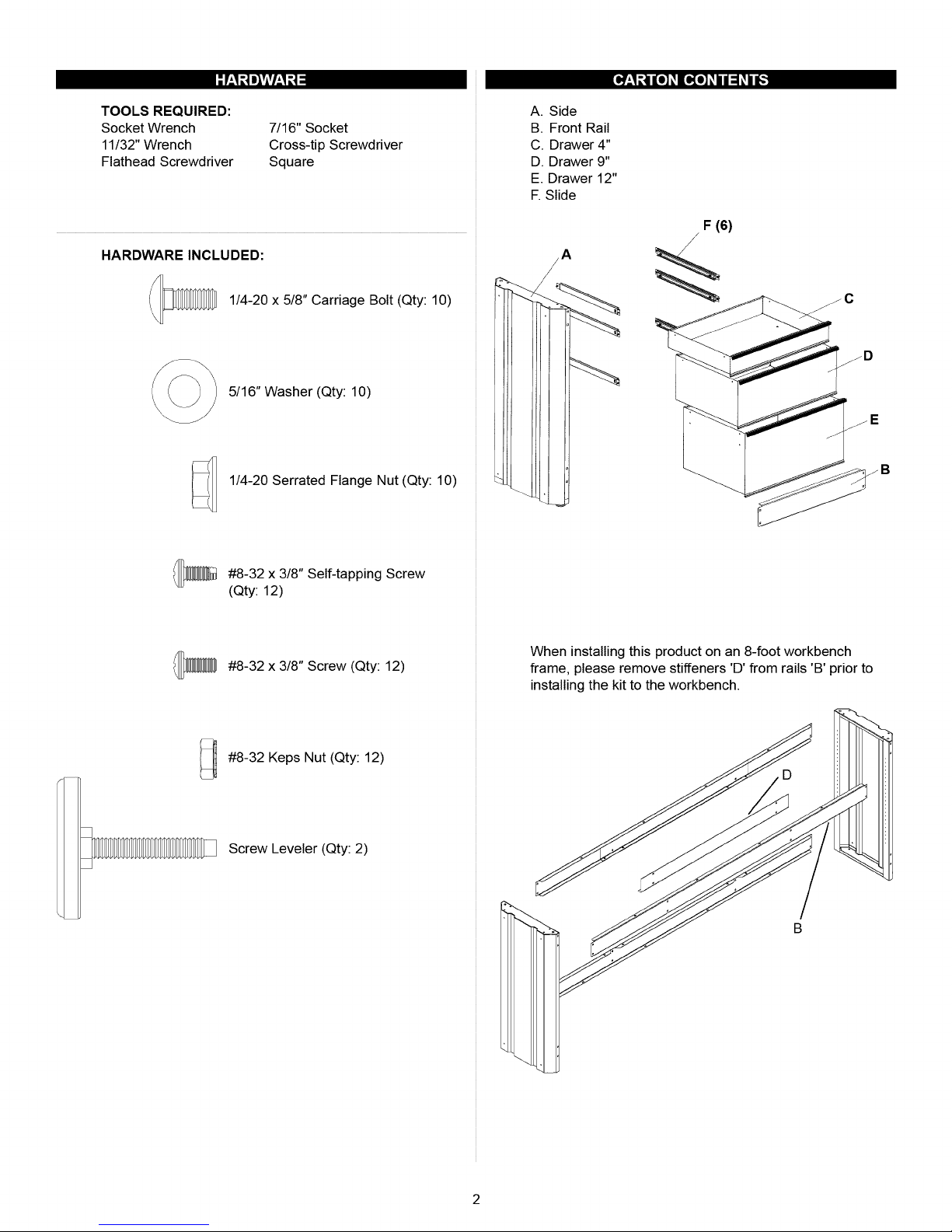
A. Side
B. Front Rail
C. Drawer 4"
D. Drawer 9"
E. Drawer 12"
E Slide
/
F (6)
#8-32 x 3/8" Self-tapping Screw
(Qty: 12)
#8-32 x 3/8" Screw (Qty: 12)
#8-32 Keps Nut (Qty: 12)
Screw Leveler (Qty: 2)
When installing this product on an 8-foot workbench
frame, please remove stiffeners 'D' from rails 'B' prior to
installing the kit to the workbench.
B
7-'_.'_1=I_N:]k'J
Items Needed:
Side (Qty:l)
Screw Leveler (Qty: 2)
Items Needed:
Front Rail (Qty: 1)
1/4-20 x 5/8" Carriage Bolt (Qty: 10)
5/16" Washer (Qty: 10)
1/4-20 Serrated Flange Nut (Qty: 10)
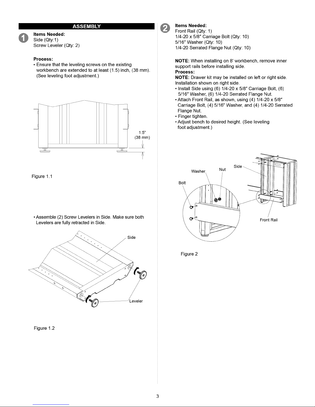
Process:
• Ensure that the leveling screws on the existing
workbench are extended to at least (1.5) inch, (38 mm).
(See leveling foot adjustment.)
(38 mm)
Figure 1.1
NOTE: When installing on 8' workbench, remove inner
support rails before installing side.
Process:
NOTE: Drawer kit may be installed on left or right side.
Installation shown on right side.
• Install Side using (6) 1/4-20 x 5/8" Carriage Bolt, (6)
5/16" Washer, (6) 1/4-20 Serrated Flange Nut.
• Attach Front Rail, as shown, using (4) 1/4-20 x 5/8"
Carriage Bolt, (4) 5/16" Washer, and (4) 1/4-20 Serrated
Flange Nut.
• Finger tighten.
• Adjust bench to desired height. (See leveling
foot adjustment.)
1.5"
Side
Washer
Bolt \
,\
\
\
Nut
\
\
\
•Assemble (2) Screw Levelers in Side. Make sure both
Levelers are fully retracted in Side.
Side
J
Figure 1.2
Front Rail
Figure 2
 Loading...