

Craftsman 149236222 Owner’s Manual
S_/A/RS
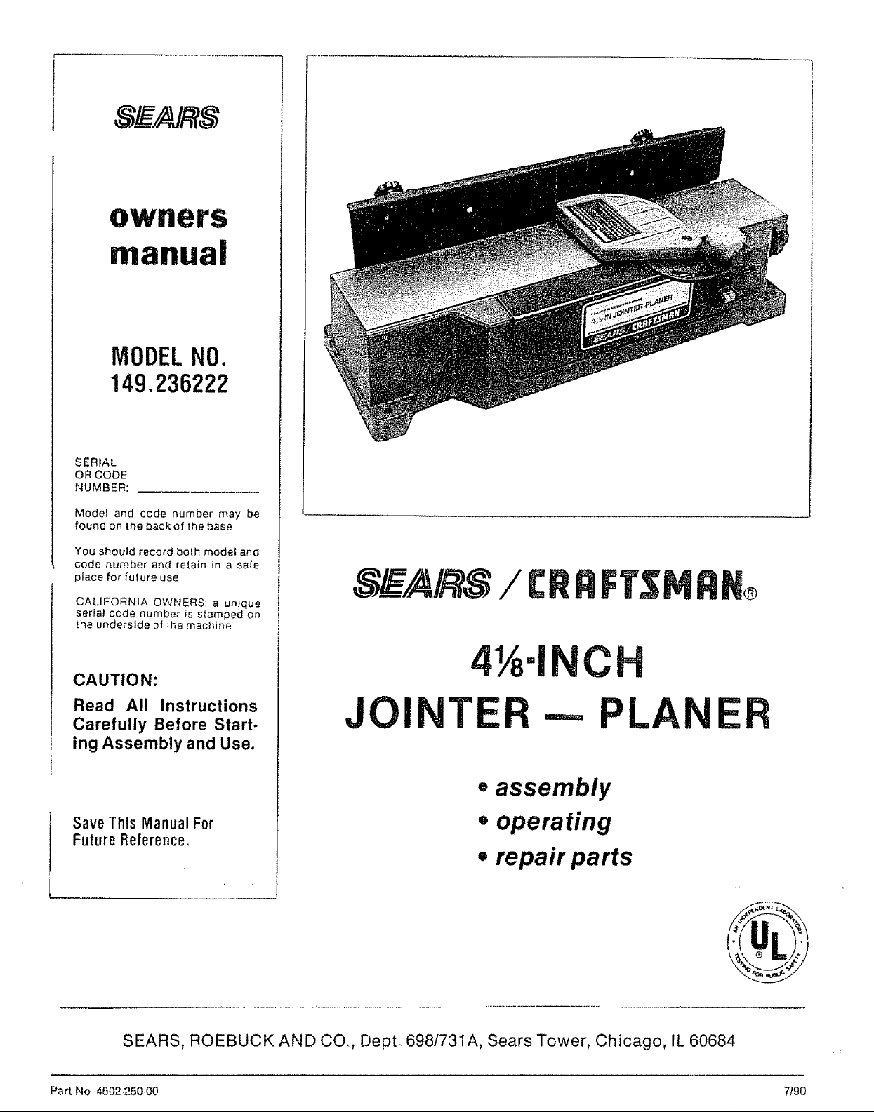
owners
manual
MODELNO.
149.236222
SERIAL
OR CODE
NUMBER:
Model and code number may be
found on the back of the base
You should record both model and
code number and re_.ain in a safe
place for fulure use
CALIFORNIA OWNERS: a unique
serial code number is slamped on
the underside of !he machine
CAUTION:
Read All Instructions
Carefully Before Start.
ing Assembly and Use.
Save This Manual For
FutureReference,
S_FAIRS/ CRAFT$IvtRN_
41_-I C
JOINTER-- PLANER
=assembly
, operating
• repair parts
SEARS, ROEBUCK AND CO. DepL 6981731A, Sears Tower, Chicago, IL 60684
Part No 4502.250-00 7f90

FULL ONE.YEAR WARRANTY ON CRRFTSMRN ,JOINTER -- PLANER
If within one year from the date of purchase, this Craftsman Jointer -- Planer fails due to a defect
in material or workmanship, Sears will repair it, free of charge.
WARRANTY SERVICE IS AVAILABLE BY CONTACTING THE NEAREST SEARS STORE OR SERVICE
CENTER IN THE UNITED STATES.
This warranty gives you specific legal rights and you may also have other rights which vary from
state to state°
Sears, Roebuck and Co. Dept. 698173tA, Sears Tower, Chicago, IL 60684..
GENERAL SAFETY RULES FOR POWER TOOLS
1. KNOW YOUR POWER TOOL
For your own safety, read the owner's manual carefully
Learn its application and limitations as well as the specific
hazards peculiar to this tool
2 GROUNDING INSTRUCTIONS
A All grounded, cord-connected tools:
In the event of a malfunction or breakdown, grounding pro°
vtdes a path of ]east resistance for electric current to reduce
the risk of electric shock This Iool is equipped with an
electric cord having an equipment.grounding conductor and
a grounding plug. The plug must be plugged into a matching
outlet that is properly installed and grounded in accordance
with all local codes and ordinances.
Do not modify the plug provided - if it will not fit the outlet,
have the proper outlet instafled by a qualified electrician
Improper connection of the equipment-grounding conductor
can result in a risk of electric shock The conductor wilh
insulation having an outer surface that is green with or with-
out yeltow stripes is the equipment-grounding conductor If
repair or replacement of the electric cord or plug is necessary,
do not connect the equipment-grounding conducto_ to a live
terminal
Check with a qualified electrician or serviceman if the
grounding instruclions are not complelely understood, or if
in doubt as to whether the too] is properly grounded
The use of any Extension Cord will cause some loss of power
To keep this Io a minimum and to prevent overheating and
motor burn-out, use the table below to determine the MINI..
MUM wire size (A.WG) Extension Cord
Use only 3-wire extension cords that have 3-prong grounding
plugs, and 3-pole receptacles that accept the tool's plug
Extension Cord Length Wire Size, A WG
25 Feet 16
50 Feet 16
100 Feet 14
Extension Cords suitable tor use with your Joinler-Ptaner are
available at your nearest Sears Calalog Order or Retail Store
Repair or replace damaged or worn cord immediately
B Grounded, cord.connected tools intended for use on a
supply circuit having a nominal rating Jess than 150 votts:
This tool is intended for use on a circuit that has an outJet
that looks like the one illustrated in Sketch A in Figure 1. The
too] has a grounding plug that looks like the plug illustrated
in Sketch A in Figure ! A temporary adapter, which looks like
the adapter illustrated in Sketches B and C, may be used to
connect this plug to a 2-pole receptacle as shown in Sketch
B if a properly grounded outlet is not available. The temporary
adapter should be used only until a properly grounded outlel
can be tnstatted by a qualified electrician. The green_colored
rigid ear, lug, ete extending from the adapter must be con..
nected to a permanent ground such as a properly grounded
outlet box
Adapter
(C) Mea_ls
Figure I -- Wiring Methods
_L
KEEP GUARDS IN PLACE
in working order and in proper adjustment and alignment.
4
REMOVE ADJUSTING KEYS AND WRENCHES
Form habit of checking to see that keys and adjusting
wrenches are removed from tool before turning on lool
5
KEEP WORK AREA CLEAN
Cluttered areas and benches invite accidents
6
DON'TUSE IN DANGEROUS ENVIRONMENT
Don't use power tools in damp or wet feeations, or expose
them to ratn_ Keep work area well illuminated
7 KEEP CHILDREN AWAY
All visttors should be kept a safe distance from work area
8. MAKE WORKSHOP KID PROOF
with padlocks, master switches, or by removing starter keys
9. DON'T FORCE TOOL
It will do the job better and be safer at the rate for which it
was designed.
10. USE RIGHT TOOL
Don't force tool or attachment to do a job for which it was nol
designed.
11: WEAR PROPER APPAREL
No loose clothing, gloves, neckties, rings, bracelets, or
jewelry to get caught in rnoving parts. Nonslip footwear Is
recommended Wear protective hair covering to contain long
hair
12. ALWAYS USE SAFETY GLASSES
Also use face or dust mask if cutting operation is dusty
Everyday eyeglasses only have impact resistant lenses They
are NOT safety glasses
!3 SECURE WORK
Use clamps or a vise to hold work when practical It's safer
than using your hand and frees both hands to operate toot
14 DON'T OVERREACH
Keep your proper footing and balance at all times
15 MAINTAIN TOOLS IN TOP CONDITION
Keep tools sharp and clean for best and safest performance
Follow instructions for lubricating and changing accessories
16 DISCONNECT TOOLS FROM POWER SOURCE
before servicing and when changing accessories such as
blades, bits, cutters, or when mounting and re.mounting
motor.
17..AVOID ACCIDENTAL STARTING
Make sure switch is in *'OFF" position before plugging in
cord
18
USE RECOMMENDED ACCESSORIES
Consult the owner's manual for recommended accessories.
Use of improper accessories may be hazardous
19.
NEVER STAND ON TOOL
Serious injury could occur if the tool is tipped or if the cutting
1ool is unintentionally contacted
20 CHECK DAMAGED PARTS
Before further use of the tool, a guard or other part that is
damaged should be carefully checked to ensure that ii will
operate properly and perform its intended function - check
for alignment of moving parts, btnding of moving parts,
breakage of parts, mounting, and any other conditions that
• may affect its-operation A guard or other part that.is damaged
should be properly repaired or replaced.
21..DIRECTION OF FEED
Feed work into a blade or cutter against the direction of
rotation of the blade or cutter only
22 NEVER LEAVE TOOL RUNNING UNATTENDED TURN
POWER OFF. Don't leave tool until it comes to a complete
stop
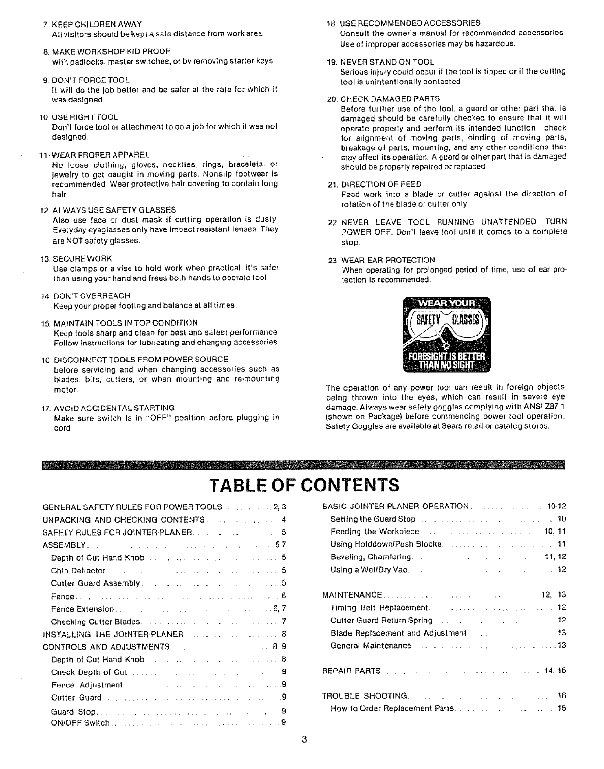
23. WEAR EAR PROTECTION
When operating for prolonged period of time, use of ear pro-
tection is recommended
The operation of any power tool can result in foreign objects
being thrown into the eyes, which can result in severe eye
damage. A_ways wear safety goggles complying with ANSI Z87 1
(shown on Package) before commencing power tool operation.
Safety Goggtes are available at Sears retail or catalog stores.
TABLE OF CONTENTS
GENERAL SAFETY RULES FOR POWER TOOLS 2, 3
UNPACKING AND CHECKING CONTENTS 4
SAFETY RULES FOR JOtNTER-PLANER 5
ASSEMBLY .. 5..7
Depth of Cut Hand Knob 5
Chip Deflector 5
Cutter Guard Assembly 5
Fence . _ 6
Fence Extension ....... 6, 7
Checking Cutter Blades 7
INSTALLING THE JOtNTER-PLANER 8
CONTROLS AND ADJUSTMENTS 8, 9
Depth of Cut Hand Knob 8
Check Depth of Cut ........... 9
Fence Adjustment 9
Cutter Guard 9
Guard Stop 9
ONfOFF Switch 9
BASIC JOtNTER-PLANER OPERATION .................. 10-12
Setting the Guard Stop ................................. 10
Feeding the Workplace .......................... 10, 11
Using HolddownfPush Blocks ......................... 11
Beveling, Chamfering ........................ 11, 12
Using a Wet/Dry Vac ................................... 12
MAINTENANCE ..................................... 12, 13
Timing Belt Replacement .................................. 12
Cutter Guard Return Spring .............................. 12
Blade Replacement and Adjustment ..................... 13
General Maintenance ...................................... 13
REPAIR PARTS ..................................... 14, 15
TROUBLE SHOOTING ................................... 16
How to Order Replacement Parts ........................... 16
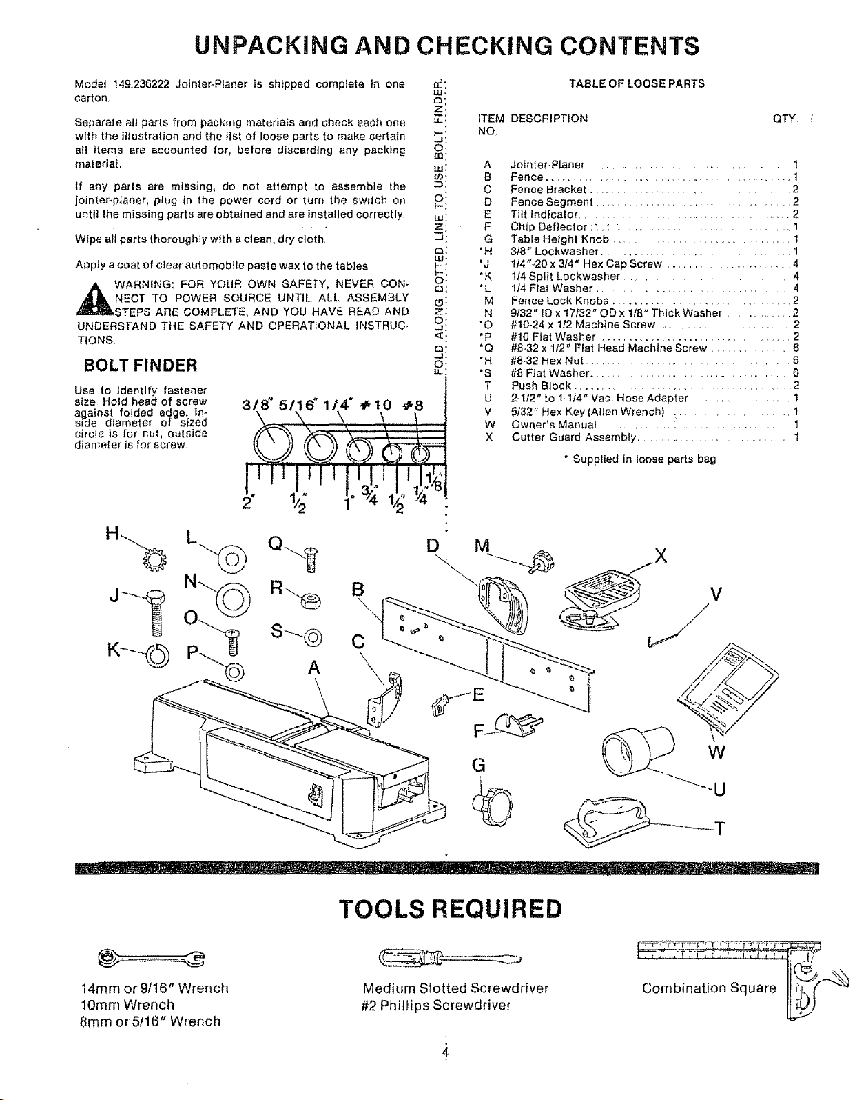
UNPACKING AND CHECKING CONTENTS
Model 149236222 Jolnter-Planer is shipped complete tn one
carton,
Separate all parts from packing materials and check each one
with the illustration and the tist of loose parts to make certatn
all items are accounted for, before discarding any packing
material
If any parts are missing, do not attempt to assemble the
jointer-planer, plug in the power cord or turn the switch on
until the missing parts are obtained and are installed correctly.
Wipe all parts thoroughly with a clean, dry etoth
Apply a coat of cleat automobile paste wax to the tables
WARNING: FOR YOUR OWN SAFETY, NEVER CON-
NECT TO POWER SOURCE UNTIL ALL ASSEMBLY
STEPS ARE COMPLETE, AND YOU HAVE READ AND
UNDERSTAND THE SAFETY AND OPERATIONAL INSTRUC-
TIONS.
BOLT FINDER
Use to identify fastener
size Hold head of screw
against folded edge. tn:
s_de diameter or s_zea
circle is for nut, outside
diameter is for screw
318' 5116" 1/?
lilt
2" 4 1
÷t0 _8
\,
'J ,J
Ul,
D:
Z,
E: ITEM
b: NO,
O:
m:
LU: A
03. B
D: C
O: D
ua: E
z: F
-a: G
o: "H
a: *L
(9: M
Z: N
q! -o
_:. *p
2! "s
Ill ,,
TABLE OF LOOSE PARTS
DESCRIPTION QTY,
Jointer-Planer ................................. 1
Fence .............................................. 1
Fence Bracket ......................................... 2
Fence Segment ............................ 2
Tilt Indicator. ............................ 2
Chip Deflector ;: ,; .................... 1
Table Height Knob ................................... 1
3f8" Lockwasher ..................................... 1
1t4"-20 x 3t4" Hex Cap Screw .......................... 4
.K
1f4 Split Lockwasher ....................... 4
1t4 Fiat Washer .......................... 4
Fence Lock Knobs ............................ 2
9132" ID x 17f32" OD x 1t8" Thick Washer .......... 2
#10..24 x 112Machine Screw ........................ 2
#10 Flat Washer ...................................... 2
#8-32 x 112" Flat Head Machine Screw ............... 6
"a
*R
#8-32 Hex Nut .............................. 6
#8 Flat Washer ................................ 6
T
Push Block ............................................ 2
U
2-112" to 1..1f4" Vac Hose Adapter .................... 1
V
5t32" Hex Key (Allen Wrench) . ................ 1
W
Owner's Manual ...................................... 1
X
Cutter Guard Assembly ...................... 1
• Supplied in loose parts bag
14mm or 9116" Wrench
10mm Wrench
8mm or 5116" Wrench
TOOLS REQUIRED
Medium Slotted Screwdriver
#2 Phillips Screwdriver
, !, ! ,_, _, I, I , _q:_,tt"
Combination Square
SAFETY RULES FOR JOINTER--PLANER
Safety is a combination of operator common senso and alertness at all times when the Jointer--Planer is being
used. Study these rules and general safety rules before operating and retain them for future use.
1, WEAR EYE PROTECTION
2 NEVER MAKE JOINTiNG OR PLANING CUT DEEPER THAN
1t8 iNCH -- PER PASS
3 FEED WORKPIECE AGAINST ROTATION OF CUTTER
4 KEEP FINGERS AWAY FROM REVOLVING CUTTER -- use
fixtures when necessary
5, NEVER PERFORM JOINTING OR PLANING OPERATION
WITH CUTTER HEAD GUARD REMOVED
6 NEVER FORCE CUTTING ACTION Stalttng or partial stalling
of motor can cause major damage. Allow motor to reach full
speed before cutting,
7. NEVER - Attempt to perform an abnormal or lJttte used
operation without study and the use of adequate hold down
/push blocks, jigs, fixtures, stops, etc
8 NEVER- Attempt to cut small pieces.
WARNING: DO NOT AT ANY TIME LET BRAKE FLUIDS, GASOLINE, PENETRATING OILS, ETC
COME tN CONTACT
WITH PLASTIC PARTS. THEY CONTAIN CHEMICALS THAT CAN DAMAGE
AND/OR DESTROY PLASTICS.
9 ALWAYS - Use hold downfpush blocks for jointing material
narrower than 3 inches, or planing material thinner than 3
inches
10 ALWAYS., Keep cutter sharp
11 NEVER- Use in an explosive atmosphere Normal sparking of
motor may ignite fumes
12 OUTDOOR EXTENSION CORD USE. When toot is used
outdoors, use only extension cords suitable for use outdoors
Outdoor approved cords are marked with the suffix W-A, for
example- SJTW,-A or SJOW-A
13. ALWAYS use identical replacement parts when servicing
14 This tool is intended for RESIDENTIAL USE ONLY,
WARNING: DO NOT ALLOW FAMILIARITY (GAINED FROM
FREQUENT USE OF YOUR JOfNTER--PLANER) TO BECOME
COMMONPLACE ALWAYS REMEMBER THAT A CARELESS
FRACTION OF A SECOND IS SUFFICIENT TO INFLICT SEVERE
INJURY,
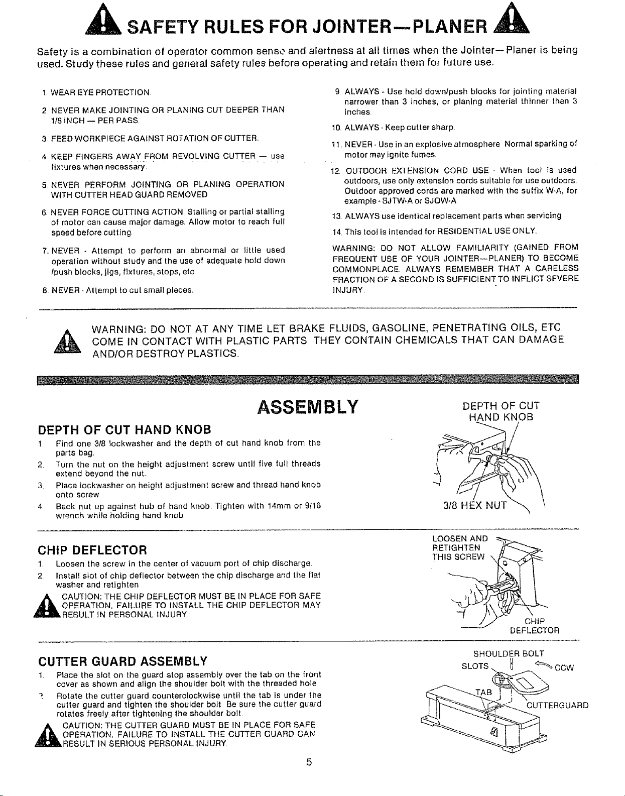
ASSEMBLY
DEPTH OF CUT HAND KNOB
1 Find one 3f8 tockwasher and the depth of cut hand knob from the
parts bag.
2 Turn the nut on the height adjustment screw until five full threads
extend beyond the nut.,
3 Place !ockwasher on height adjustment screw and thread hand knob
onto screw
4 Back nut up against hub of hand knob Tighten with 14mm or 9/16
wrench while hotdtng hand knob
CHIP DEFLECTOR
1 Loosen the screw in the center of vacuum port of chip discharge,
2 Install slot of chip deflector between the chip discharge and the fiat
washer and retighten
,_ CAUTION: THE CHIP DEFLECTOR MUST BE IN PLACE FOR SAFE
OPERATION. FAILURE TO INSTALL THE CHIP DEFLECTOR MAY
RESULT iN PERSONAL INJURY
CUTTER GUARD ASSEMBLY
1 Place the slot on the guard stop assembty over the tab on the front
cover as shown and a]ign the shoulder boff with the threaded hole
7 Rotate the cutter guard counterclockwise until the tab is under the
cutter guard and tighten the shoulder bolt Be sure the cutter guard
rotates freely after tightening the shoulder bolt
DEPTH OF CUT
HAND KNOB
3/8 HEX NUT
LOOSEN AND
RETIGHTEN
THiS SCREW \
CH1P
DEFLECTOR
SHOULDER BOLT
SLOTS CCW
CUTTERGUARD
OPERATION, FAILURE TO INSTALL THE CUTTER GUARD CAN
,_CAUTION: THE CUTTER GUARD MUST BE tN PLACE FOR SAFE
RESULT IN SERIOUS PERSONAL INJURY
 Loading...