

Page 1
Operator's Manual
1450 Series Engine
Chipper Shredder
For questions, call
1-800-4-iViY-HOME
CAUTION: Before using
this product, read this
manual and follow ail
safety rules and operating
instructions.
Sears, Roebuck and Co., Hoffman Estates, IL 60179, U.S.A.
Visit our web site: www.craftsman.com
• SAFETY
• ASSEMBLY
• OPERATION
• MAINTENANCE
• PARTS LIST
• ESPAÑOL
FORM NO. 769-05040
5/4/2009
Page 2

TABLE OF CONTENTS
Warranty Statement
Safe Operation Practices
Safety Labeis.............................................Page 7
Assembiy
Operation...................................................Pages 12-13
Service and Maintenance..........................Pages 14-17
Off-Season Storage...................................Page 18
...................................................
..................................
..........................
Page 2
Pages 3-6
Pages 8-11
Troubie Shooting
Parts List
Labei Map
Repair Protection Agreement
Españoi....................................................Page 35
Service Numbers
..............................................................
.....................................
...............................................
..................
..................................................
Page 19
Page 31
Page 34
Page 20-30
Back Oover
WARRANT
I
CRAFTSMAN FULL WARRANTY
When operated
within two years from the date of purchase, return it to any Sears store. Sears Parts & Repair Service Center, or other Craftsman outlet in the
United States for free repair (or replacement it repair proves impossible).
This warranty applies for only 90 days from the date of purchase it this chipper shredder is ever used for commercial or rental purposes.
This warranty covers ONLY defects in material and workmanship. Sears will NOT pay for:
• Expendable items that become worn during normal use, including but not limited to blades, spark plug, air cleaner, flail screen and catcher
bag.
• Standard maintenance servicing, oil changes, or tune-ups.
• Tire replacement or repair caused by punctures from outside objects, such as nails, thorns, stumps, or glass.
• Tire or wheel replacement or repair resulting from normal wear, accident, or improper operation or maintenance.
• Repairs necessary because of operator abuse, including but not limited to damage caused by impacting objects that bend the frame or
crankshaft, or over-speeding the engine.
• Repairs necessary because of operator negligence, including but not limited to, electrical and mechanical damage caused by improper
storage, failure to use the proper grade and amount of engine oil, or failure to maintain the equipment according to the instructions
contained in the operator's manual.
• Engine (fuel system) cleaning or repairs caused by fuel determined to be contaminated or oxidized (stale). In general, fuel should be used
within 30 days of its purchase date.
• Normal deterioration and wear of the exterior finishes, or product label replacement.
and
maintained according to all supplied instructions, if this chipper shredder fails due to a defect in material or workmanship
This warranty applies only while this product is within the United States.
This warranty gives you specific legal rights, and you may also have other rights which vary from state to state.
Sears, Roebuck and Co., FI off man Estates, IL 60179
PRODUCT SPECIFICATIONS
Engine Series: 1450
Engine Oil Type: SAE 30
Engine Oil Capacity: 28 ounces
Fuel: Unleaded Gasoline
Spark Plug: Champion® RC-12YC
Spark Plug Gap: .030”
§ Sears Brands, LLC
MODEL NUMBER
Model Number....................................................
Serial Number
Date of Purchase
....................................................
...............................................
Record the model number, serial number
and date of purchase above
Page 3

SAFETY INSTRUCTIONS
J
A WARNING
This symbol points out important safety instructions which, it not
followed, could endanger the personal safety and/or property of
yourself and others. Read and follow all instructions in this manual
before attempting to operate this machine. Failure to comply with
these instructions may result in personal injury. When you see this
symbol, HEED ITS WARNING!
AWARNING
CALIFORNIA PROPOSITION 65
Engine Exhaust, some of its constituents, and certain vehicle
components contain or emit chemicals known to State of California
to cause cancer and birth defects or other reproductive harm.
TRAINING
Read, understand, and follow all instructions on the machine and
in the manual(s) before attempting to assemble and operate.
Keep this manual in a safe place for future and regular reference
and for ordering replacement parts.
Read the Operator’s Manual and follow all warnings and safety
instructions. Failure to do so can result in serious injury to the
operator and/or bystanders. For questions, call 1-800-659-5917.
Be familiar with all controls and their proper operation. Know how
to stop the machine and disengage them quickly.
Never allow children under 16 years of age to operate this
machine. Children 16 and over should read and understand the
instructions and safe operation practices in this manual and on
the machine and be trained and supervised by an adult.
Never allow adults to operate this machine without proper
instruction.
Keep bystanders, pets, and children at least 75 feet from the
machine while it is in operation. Stop machine it anyone enters
the area.
Never run an engine indoors or in a poorly ventilated area. Engine
exhaust contains carbon monoxide, an odorless and deadly gas.
Do not put hands and feet near rotating parts or in the feeding
chambers and discharge opening. Contact with the rotating
impeller can amputate fingers, hands, and feet.
Never attempt to unclog either the feed intake or discharge
opening, remove or empty bag, or inspect and repair the machine
while the engine is running. Shut the engine off and wait until all
moving parts have come to a complete stop. Disconnect the spark
plug wire and ground it against the engine.
A DANGER
This machine was built to be operated according to the safe opera
tion practices in this manual. As with any type of power equipment,
carelessness or error on the part of the operator can result in
serious injury. This machine is capable of amputating fingers, hands,
toes and feet and throwing debris. Failure to observe the following
safety instructions could result
in
serious injury or death.
___________
AWARNING
Your Responsibility—
persons who read, understand and follow the warnings and instruc
tions in this manual and on the machine.
SAVE THESE INSTRUaiONS!
PREPARATION
• Thoroughly inspect the area where the equipment is to be used.
Remove all rocks, bottles, cans, or other foreign objects which
could be picked up or thrown and cause personal injury or
damage to the machine.
• Always wear safety glasses or safety goggles during operation
and while performing an adjustment or repair, to protect your
eyes. Thrown objects which ricochet can cause serious injury to
the eyes.
• Wear sturdy, rough-soled work shoes and close-fitting slacks and
shirts. Loose fitting clothes or jewelry can be caught in movable
parts. Never operate this machine in bare feet or sandals. Wear
leather work gloves when feeding material in the chipper chute.
• Before starting, check all bolts and screws for proper tightness to
be sure the machine is in safe working condition. Also, visually
inspect machine for any damage at frequent intervals.
• Maintain or replace safety and instructions labels, as necessary.
Restrict the use of this power machine to
Page 4

SAFETY INSTRUCTION
I
Safe Handling of Gasoline;
To avoid personal
handling gasoline. Gasoline is extremely flammable and the vapors are
explosive. Serious personal injury can occur when gasoline is spilled
on yourself or your clothes which can ignite. Wash your skin and
change clothes immediately.
• Use only an approved gasoline container.
• Never fill containers inside a vehicle or on a truck or trailer bed
with a plastic liner. Always place containers on the ground away
from your vehicle before filling.
• When practical, remove gas-powered equipment from the truck
or trailer and refuel it on the ground. If this is not possible, then
refuel such equipment on a trailer with a portable container, rather
than from a gasoline dispenser nozzle.
• Keep the nozzle in contact with the rim of the fuel tank or
container opening at all times until fueling is complete. Do not use
a nozzle lock-open device.
• Extinguish all cigarettes, cigars, pipes and other sources of
ignition.
• Never fuel machine indoors.
• Never remove gas cap or add fuel while the engine is hot or run
ning. Allow engine to cool at least two minutes before refueling.
• Never over fill fuel tank. Fill tank to no more than
bottom of filler neck to allow space for fuel expansion.
• Replace gasoline cap and tighten securely.
• If gasoline is spilled, wipe it off the engine and equipment. Move
unit to another area. Wait 5 minutes before starting the engine.
• To reduce tire hazards, keep machine free of grass, leaves, or
other debris build-up. Clean up oil or fuel spillage and remove any
fuel soaked debris.
• Never store the machine or fuel container inside where there is an
open flame, spark or pilot light as on a water heater, space heater,
furnace, clothes dryer or other gas appliances.
injury
or property damage use extreme care in
'/2
inch below
OPERATION
• Do not put hands and feet near rotating parts or in the feeding
chambers and discharge opening. Contact with the rotating
impeller can amputate fingers, hands, and feet.
• Before starting the machine, make sure the chipper chute, feed
intake, and cutting chamber are empty and free of all debris.
• Thoroughly inspect all material to be shredded and remove any
metal, rocks, bottles, cans, or other foreign objects which could
cause personal injury or damage to the machine.
• If it becomes necessary to push material through the shredder
hopper, use a small diameter stick. Do not use your hands or feet.
If the impeller strikes a foreign object or it your machine should
start making an unusual noise or vibration, immediately shut
the engine off. Allow the impeller to come to a complete stop.
Disconnect the spark plug wire, ground it against the engine and
perform the following steps:
a. Inspect for damage.
b. Repair or replace any damaged parts.
c. Check for any loose parts and tighten to assure continued
Do not allow an accumulation of processed material to build up in
the discharge area. This can prevent proper discharge and result
in kickback of material through the feed opening.
Do not attempt to shred or chip material larger than specified
on the machine or in this manual. Personal injury or machine
damage could result.
Never attempt to unclog either the feed intake or discharge
opening while the engine is running. Shut the engine off, wait until
all moving parts have stopped, disconnect the spark plug wire and
ground it against the engine before clearing debris.
Never operate without the shredder hopper, chipper chute, or
chute deflector properly attached to the machine. Never empty or
change discharge bag while the engine is running.
Keep all guards, deflectors and safety devices in place and
operating properly.
Keep your face and body back and to the side of the chipper
chute while feeding material into the machine to avoid accidental
kickback injuries.
Never operate this machine without good visibility or light.
Do not operate this machine on a paved, gravel or non-level
surface.
Do not operate this machine while under the influence of alcohol
or drugs.
Muffler and engine become hot and can cause a burn. Do not
touch.
Never pick up or carry machine while the engine is running.
If situations occur which are not covered in this manual, use care
and good judgement. Contact Customer Support for assistance
and the name of the nearest service dealer.
MAINTENANCE & STORAGE
Never tamper with safety devices. Check their proper operation
regularly.
Check bolts and screws tor proper tightness at frequent intervals
to keep the machine in safe working condition. Also, visually
inspect machine for any damage and repair, it needed.
Before cleaning, repairing, or inspecting, stop the engine and
make certain the impeller and all moving parts have stopped.
Disconnect the spark plug wire and ground it against the engine
to prevent unintended starting.
Do not change the engine governor settings or overspeed the
engine. The governor controls the maximum safe operating speed
of the engine.
safe operation.
Page 5

SAFETY INSTRUCTIONS
J
• Maintain or replace safety and instruction labels, as necessary.
• Follow this manual for safe loading, unloading, transporting, and
storage of this machine.
• Never store the machine or fuel container inside where there is an
open flame, spark or pilot light such as a water heater, furnace,
clothes dryer, etc.
• Allow machine to cool at least 5 minutes before storing.
• Always refer to the operator's manual for proper instructions on
off-season storage.
• If the fuel tank has to be drained, do this outdoors.
• Observe proper disposal laws and regulations for gas, oil, etc. to
protect the environment.
• According to the Consumer Products Safety Commission (CPSC)
and the U.S. Environmental Protection Agency (EPA), this product
has an
Average Useful Life
operation. At the end of the
inspected annually by an authorized service dealer to ensure that
all mechanical and safety systems are working properly and not
worn excessively. Failure to do so can result in accidents, injuries
or death.
of seven (7) years, or 60 hours of
Average Useful Life
have the machine
DO NOT MODIFY ENGINE
To avoid serious injury or death, do not modify engine in any way.
Tampering with the governor setting can lead to a runaway engine and
cause it to operate at unsafe speeds. Never tamper with factory setting
of engine governor.
NOTICE REGARDING EMISSIONS
Engines which are certified to comply with California and federal
EPA emission regulations for SCRE (Small Cff Road Equipment) are
certified to operate on regular unleaded gasoline, and may include
the following emission control systems: Engine Modification (EM),
Cxidizing Catalyst (CC), Secondary Air Injection (SAI) and Three Way
Catalyst (TWC) it so equipped.
SPARK ARRESTOR
This machine is equipped with an internal combustion engine and
should not be used on or near any unimproved forest-covered,
brushcovered or grass-covered land unless the engine's exhaust
system is equipped with a spark arrester meeting applicable local or
state laws (it any)
If a spark arrester is used, it should be maintained in effective working
order by the operator. In the State of California the above is required
by law (Section 4442 of the California Public Resources Code). Cther
states may have similar laws. Federal laws apply on federal lands.
A spark arrester for the muffler is available through your nearest Sears
Parts and Repair Service Center.
Awarning
Page 6

SAFETY INSTRUCTION
SAFETY SYMBOLS
This page depicts
before attempting to assemble and operate.
and
describes safety symbols that may appear
Symbol Description
on
this product. Read, understand, and follow all instructions on the machine
I
-T
READ THE OPERATOR’S MANUAL(S)
Read, understand, and follow all instructions in the manual(s) before attempting to assemble and
operate
WARNING— ROTATING BLADES
Keep hands out of inletand discharge openings while machine is running. There are rotating blades
inside
BYSTANDERS
Keep bystanders, pets, and children at least 75 feet from the machine while it is in operation. Stop
machine if anyone enters the area.
WARNING—THROWN DEBRIS
Never operate without the chute deflector properly attached to the machine.
EYE PROTECTION
Always wear safety glasses or safety goggles when operating this machine.
A
WARNING:
warnings and instructions in this manual and on the machine.
Your Responsibility—Restrict the use of this power machine to persons who read, understand and follow the
SAVE THESE INSTRUaiONS!
A
Page 7
SAFETY LABELS
ADANGER
TO AVOID SERIOUS INJURY:
• Do not operate on uneven ground where unit is
unstable. Do not operate on pavement, gravel or
other hard surfaces since objects can ricochet
and cause injury.
• To avoid a fire hazard, keep leaves, grass, and other
combustible materials away from hot engine and
muffler.
• Keep children and others away from area of
operation.
• Wear approved safety glasses, gloves and ear
protection.
INSTRUCTIONS:
TO RAISE AND LOWER HOPPER
ADANGER
TO AVOID SERIOUS INJURY:
• Read the owner's manual(s) before starting and
using unit.
• Keep all shields and guards in place and securely
attached.
• Keep hands, feet, face, clothing and long hair out of
Shredder Hopper, Chipper Chute and Discharge
Chute while the engine is running. Rotating cutting
blades inside these openings will cause serious
personal injury if contacted. Material being
processed
may bounce back from inlet openings or be thrown
from the discharge chute. Long hair or loose clothing
may be pulled sucked into the inlet openings.
• Do not place branches over 1/2 inch diameter into
the large Shredder Hopper. Branches over 1/2 inch in
diameter should be placed in the Small Chipper
Chute.
• If the chipped shredder jams or becomes clogged,
immediately shut off the engine and wait for all
moving parts to come to a complete stop before
clearing.
• Do not install remove, adjust, or service the
discharge screen or any other part while the engine
is running. Blade contact can occur.
A DANGE
ROTATING CUTTING BLADES.
KEEP HANDS AND FEET OUT
OF OPENINGS WHILE MACHINE
IS RUNNING.
A DANGER
DO NOT OPERATE THIS MACHINE
UNLESS THE CHUTE DEFLECTOR
HAS BEEN PROPERLY INSTALLED.
A WARNING
oe.y
DO NOT DEPOSIT
MATERIAL LARGER THAN
1/2" DIAMETER IN LARGE
SHREDDER HOPPER.
THIS MAY DAMAGE
MACHINE.
A
0
• ROTATING CUTTING BLADES.KEEP HANDS
AND FEET OUT OF OPENING WHILE
MACHINE IS RUNNING.
• DO NOT OPERATE THIS MACHINE UNLESS
THE CHUTE DEFLECTOR HAS BEEN
PROPERLY INSTALLED AND IS SECURED
WITH THE HAND KNOBS.
m
Page 8
ASSEMBLY
IMPORTANT:
Be certain to service engine with gasoline and oil as instructed in the
Operation section of this manual before operating your machine.
NOTE:
is observed from the operating position.
Reference to right and left hand side of the Chipper Shredder
This unit is shipped without gasoline or oil in the engine.
OPENING CARTON
1. Cut each corner of the carton vertically from top to bottom.
2. Remove all loose parts.
3. Remove loose packing material.
REMOVING UNIT FROM CARTON
1. Lift unit from the rear to detach it from underlying carton material
and roll unit out of carton.
2. Check carton thoroughly for any other loose parts.
LOOSE PARTS IN CARTON
Hopper Assembly
Bag
Chute Deflector
Chipper Chute
Tamper
Safety Glasses
Engine Cil
Cwner’s Manual
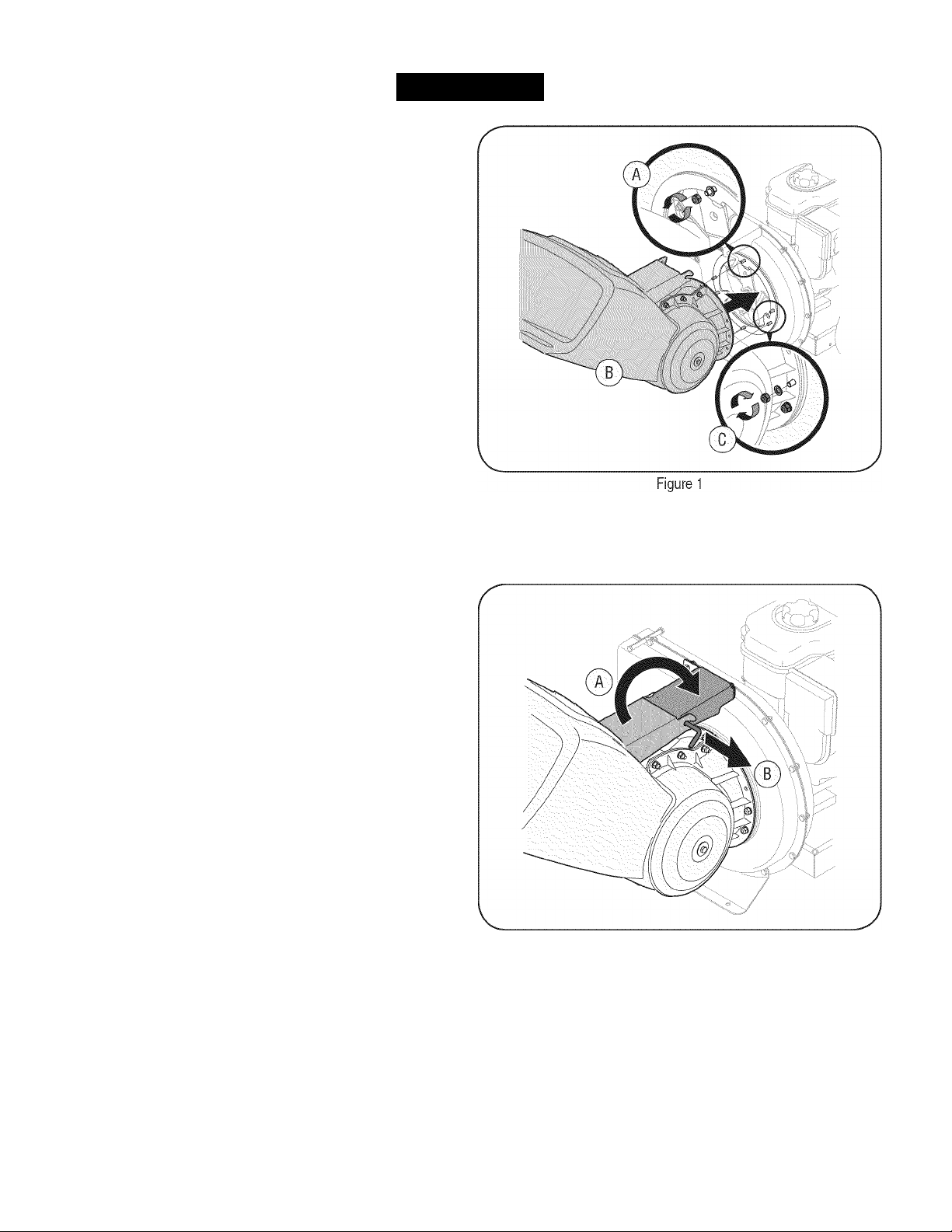
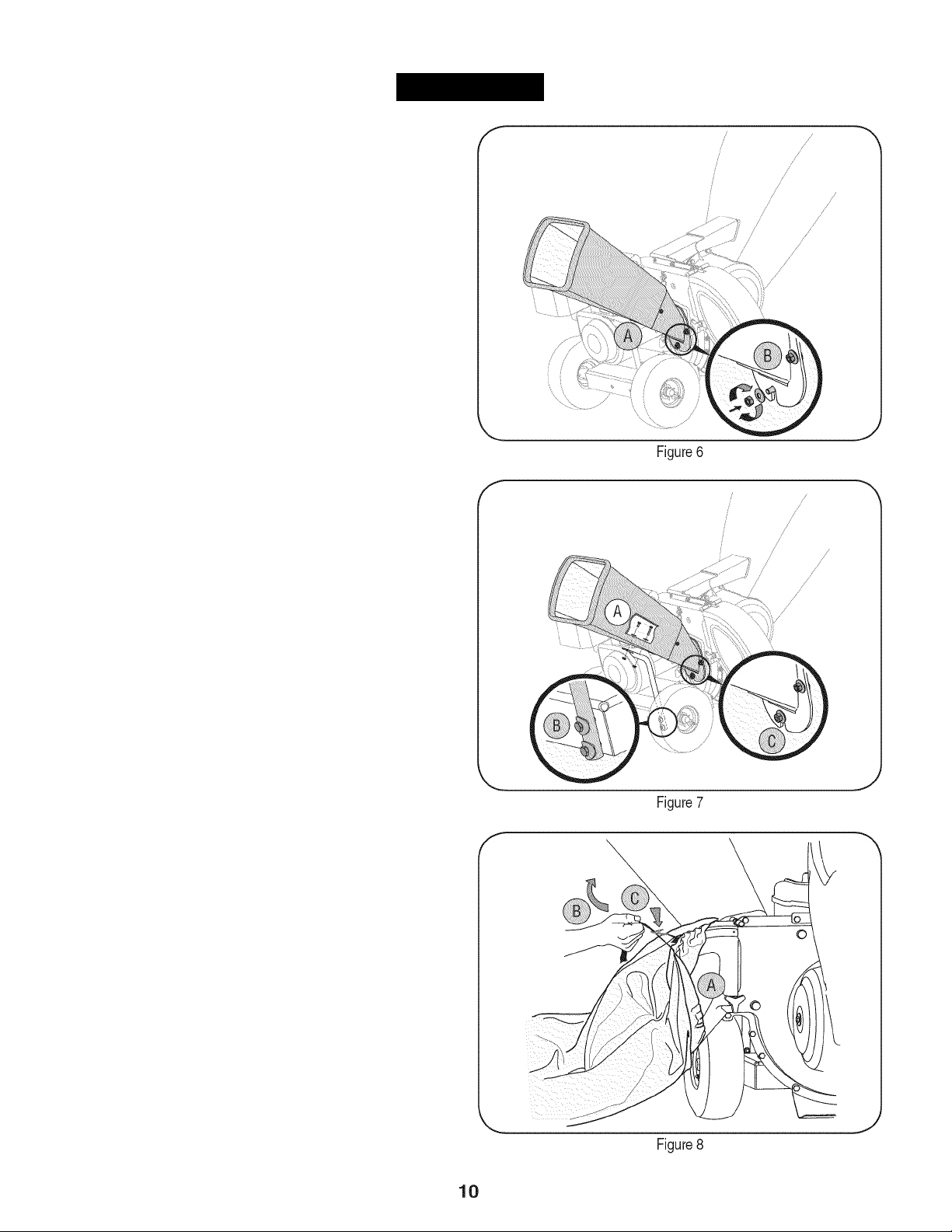
ATTACHING THE HOPPER ASSEMBLY
1. A. Remove six hex nuts and washers from the weld studs on the
impeller housing. Do not remove support plate. See Figure 1.
B. Place hopper assembly into position in front of impeller
housing, aligning holes in hopper assembly collar with weld
studs.
C. Slide hopper assembly onto weld studs and replace washers
and hex nuts. Do not tighten completely.
2. A. Lift hopper assembly up to impeller bracket assembly. See
Figure 2.
B. Slide the release rod out slightly to hook the hopper bracket
onto the rod. See Figure 2.
C. Tighten the six hex nuts that secure hopper assembly to
impeller housing and also tighten the hex nuts that secure
hopper bracket to hopper assembly.
Figure 2
Page 9
ASSEMBLY
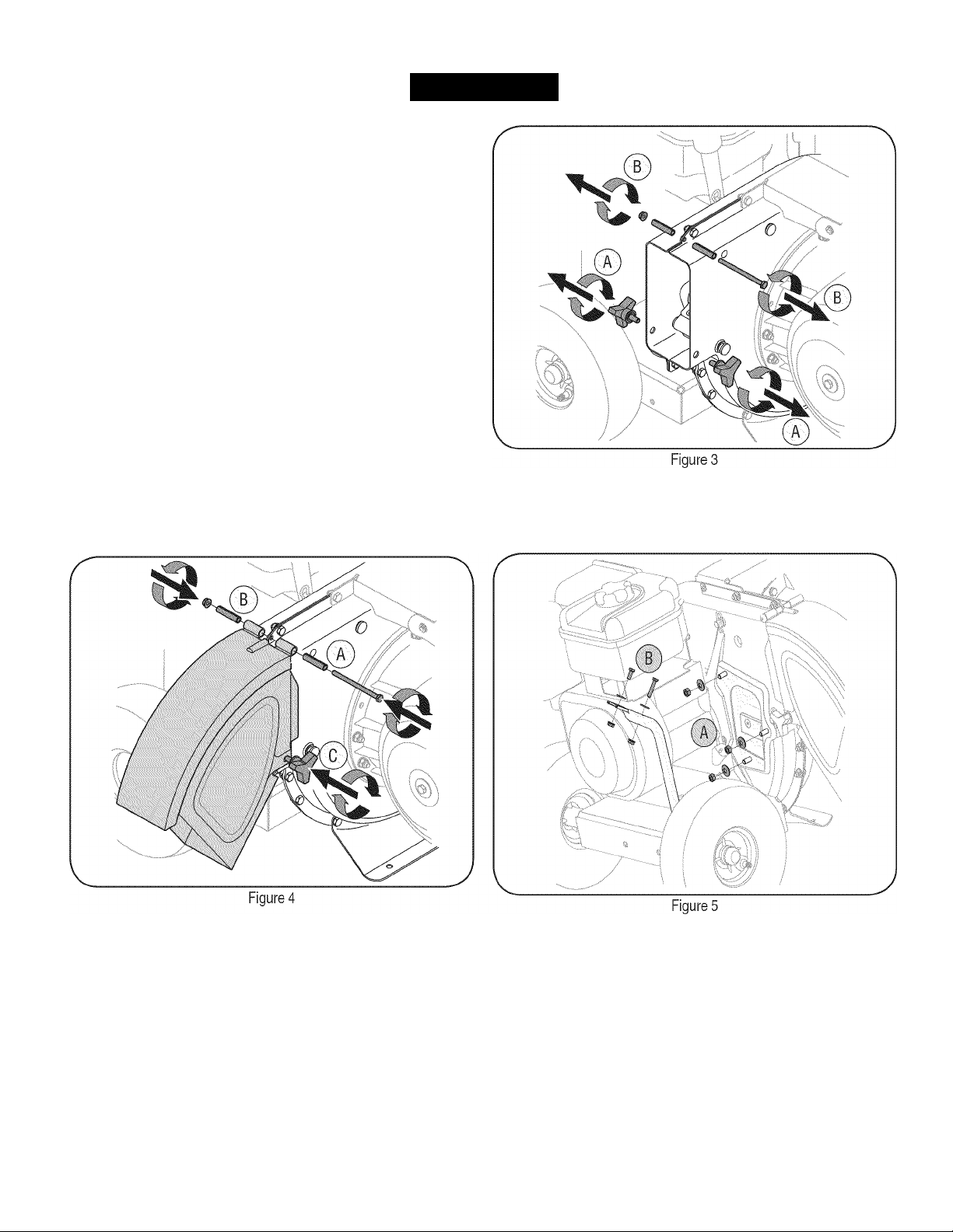
ATTACHING THE CHUTE DEFLECTOR
1. A. Remove the wing knobs from each side of the lower impeller
housing. See Figure 3.
B. Remove the hex lock nut, spacers, and hex bolt from the top of
the impeller housing.
2. A. Align the chute deflector in position on the discharge opening
and insert hex bolt with spacer through hinge on chute
deflector (spacers fit inside of hinges). See Figure 4.
B. Place second spacer over hex bolt inside other hinge and
secure with hex lock nut.
C. Secure both sides of chute deflector to impeller housing using
wing knobs previously removed.
ATTACHING THE CHIPPER CHUTE
1. A. Remove the three cupped washers and hex nuts from weld
studs around the opening on the side of the impeller housing.
See Figure 5.
B. Remove the hex bolts, flat washers, and lock nuts from the two
holes on the upper end of the support brace.
Page 10
ASSEMBLY
2.
A. Align the chipper chute over the weld studs, so the slot
bottom of the chute is facing down. See Figure 6.
B. Secure chipper chute with the three cupped washers (cupped
side against the chipper chute) and hex nuts previously
removed. Do not tighten the nuts at this time.
3. The chipper shredder was shipped with one end of the support
brace already secured to the lower frame. Loosen but do not
remove the bolts securing the brace to the frame.
A. Align the holes in the chute with the holes in the top of the
brace and attach brace to chipper chute with hardware
previously removed. The flat washers should be placed under
the bolt heads and against the inside surface of the plastic
chipper chute. Tighten securely. See Figure 7.
B. Tighten the bolts securing the support brace to the frame.
C. Tighten the three nuts on the weld studs holding the chipper
chute to the impeller housing.
ATTACHING THE BAG
1. To attach the bag:
A. Place the opening of the bag completely over the chute
deflector.
B. Pull on the drawstring until the bag is tight around chute
deflector opening.
C. Clip drawstring back on itself, tight against chute deflector to
secure into position. See Figure 8.
in
the
Page 11
OPERATION
Now that you have set up your chipper shredder for operation, get
aquainted with its controls and features. These are described below
and illustrated on this page. This knowledge will allow you to use your
new equipment to its fullest potential.
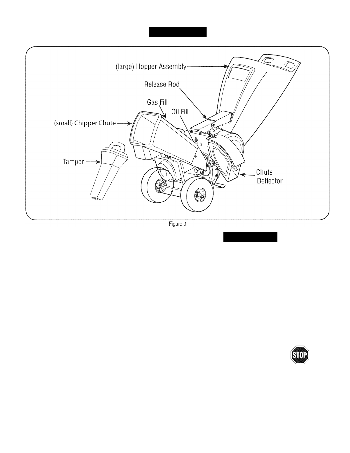
CHIPPER CHUTE
Allows twigs and small branches up to 3” in diameter to be fed into the
impeller for chipping. See Figure 9.
HOPPER ASSEMBLY
Allow leaves and small branches up to 1/2 diameter to be fed into the
impeller for chipping and shredding. Material can be raked into hopper
assembly by lowering the hopper assembly. See Figure 9.
RELEASE ROD
The release rod is located on the impeller bracket assembly and it
is used to release or lock the hopper when raising or lowering. See
Figure 9.
The operation of any chipper shredder can result in foreign objects
being thrown into the eyes, which can damage your eyes severely.
Always wear the safety glasses provided with this unit or eye shields
before chipping or shredding and while performing any adjustments
or repairs._________________________________________
TAMPER
This plug is inserted into the chipper chute to push twigs and small
branches towards the impeller blades without endangering your hands.
THROTTLE CONTROL
This lever controls the engine speed and stop function. Through three
separate positions on the lever from left to right, the operation is as
follows:
CHUTE DEFLECTOR
Chipped and shredded debris is discharged out the chute deflector.
The unit may be operated with or without the collection bag attached to
the chute deflector. See Figure 9.
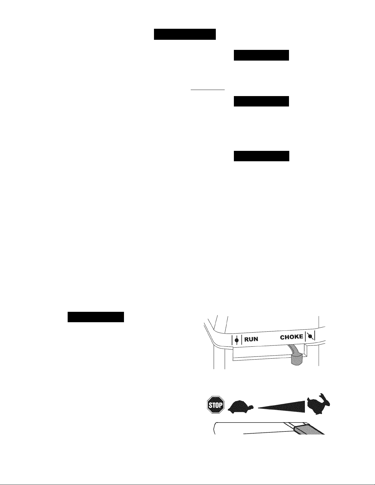
CHOKE CONTROL
The choke control is used to choke the carburetor and assist in starting
the engine.
Awarning
Start/ Run Slow/ Idle
Engine Off
Meets ANSI Safety Standards
Craftsman Yard Vacuums conform to the safety standard of the American National Standards Institute (ANSI).
11
Page 12
OPERATION
J
GAS AND OIL FILL-UP
Oil (one bottle shipped with unit)
First Time
1. Remove oil fill dipstick.
2. With the chipper shredder on level ground, use a funnel to empty
entire contents of oil bottle provided into the engine.
3. Replace oil fill dipstick and tighten.
Subsequent Uses
Only use high quality detergent oil rated with API service classification
SR SG, or SH. Select the oil's SAE viscosity grade according to the
expected operating temperature. Follow the chart below.
/Colder-
Use
5W30
■32T
►Warme?\
SAE30
Oil Viscosity Chart
Although multi-viscosity oils (5W30,10W30, etc.) improve starting
in cold weather, they will result in increased oil consumption when
used above 32°F. Check your engine oil level more frequently to avoid
possible engine damage from running low on oil.
1. Check the oil level making certain not to rub the dipstick along the
inside walls of the oil fill tube. This would result in a false dipstick
reading. Wipe dipstick clean with cloth. Replace and tighten
dipstick. Remove and check oil level. Refill to FULL mark on
dipstick, it necessary. Capacity is approximately 28 oz. Cverfilling
will cause the engine to smoke profusely and will result in poor
engine performance.
2. Replace oil fill dipstick and tighten.
Alcohol blended fuels (called gasohol or using ethanol or methanol)
can attract moisture which leads to separation and formation of acids
during storage. Acidic gas can damage the fuel system of an engine
while
To avoid engine problems, the fuel system should be emptied before
storage for 30 days or longer. Drain the gas tank, start the engine
and let it run until the fuel lines and carburetor are empty. Use
fresh fuel next season. See STORAGE Instructions for additional
information.
Never use engine or carburetor cleaner products in the fuel tank or
permanent damage may occur.
ЮТЕ: Check the fuel level periodically to avoid running out of gaso
line while operating the chipper shredder. If the unit runs out of gas as
it is chipping, it may be necessary to unclog the discharge area before
it can be restarted. Refer to SERVICE AND MAINTENANCE section.
TO START ENGINE
1. Attach spark plug wire and rubber boot to spark plug.
2. Fill tank to no more than 1/2 inch below bottom of filler neck to
provide space for fuel expansion.
3. Turn the fuel shut-off valve to the CN position.
4. Move the choke lever on the engine to CHCKE
warm engine may not require choking.) See Figure 10.
5. Move throttle control to START/RUN (Rabbit)
Figure 10. ^
6. Standing behind the unit, grasp starter handle and pull rope out
until you feel a drag.
in
storage.
A CAUTION
_____________________________________
A CAUTION
A CAUTION
N
position. (A
JL m
position. See
Awarning
Use extreme care when handling gasoline. Gasoline is extremely
flammable and the vapors are explosive. Never fuel machine indoors
or while the engine is hot or running. Extinguish cigarettes, cigars,
pipes, and other sources of ignition.
3. Keep oil level at FULL. Running the engine with too little oil can
result in permanent engine damage.
Gasoline
1. Remove fuel cap from the fuel tank.
2. Make sure the container from which you will pour the gasoline is
clean and free from rust or foreign particles. Never use gasoline
that may be stale from long periods of storage in its container.
Gasoline that has been sitting for any period longer than four
weeks should be considered stale.
3. Fill fuel tank with clean, fresh, unleaded regular gasoline only. Do
not use gasoline containing METHANCL. Replace fuel cap.
12
Л
Figure 10
Page 13

OPERATION
J
NOTE:
cycle. This noise is caused by the flails and fingers, which are part
the shredding mechanism, and it should be expected until the impeller
reaches full speed.
7. Pull the rope with a rapid, continuous, full arm stroke. Keep a firm
8. Repeat, if necessary, until engine starts. When engine starts,
9. It engine falters, move choke control back toward the CHOKE
10. ALWAYS keep the throttle control in the START/RUN position
TO STOP ENGINE
1.
A noise will be heard when finding the start of the compression
of
grip on the starter handle. Let the rope rewind slowly.
move choke control gradually toward the RUN m position..
N
position and repeat steps 5 though 8.
when operating the chipper shredder.
Move throttle control lever to slow (turtle) position.
Whenever possible, gradually reduce engine speed before
stopping engine.
Move throttle control lever to STOP or OFF position.
Turn the fuel shut-off valve to the OFF position.
Disconnect spark plug wire and ground it against the engine to
prevent accidental starting while the equipment is unattended.
CHIPPING
Branches up to 3” in diameter can be fed into the chipper chute.
Observe the following guidelines when chipping branches:
• Keep both hands firmly on the branch as you feed it into the
• Never feed more than one branch into the chipper chute at a time.
• Never feed anything other than branches (or wood) into the
• Apply intermittent pressure (force, in short pulses) while feeding
IMPORTANT:
three (3) inches into the chipper chute. Doing so can result in serious
damage to your unit's chipper blades, flails or impeller.
NOTE:
chipper blades. If a noticeable loss in performance is encountered
while chipping branches, the chipper blades should be replaced.
LOWERING THE HOPPER ASSEMBLY
1. With one hand grasp the handle at the top of the hopper assem
2. With the other hand pull out on the release rod and lower the
SHREDDING
Yard waste such as leaves and pine needles can be placed in the
hopper for shredding. After material has been processed by the shred
der blade and flails, it will be forced out of the chute deflector, and, it
attached, into a debris collection bag.
Observe the following guidelines when shredding yard debris:
• Never attempt to shred material other than normal yard debris
(leaves, twigs, pine cones, etc.).
• Avoid shredding fibrous plants such as tomato vines, palm fronds,
etc., until they are thoroughly dried out. Fresh vines do not shred
well and tend to wrap themselves around the impeller and flails.
• Place reasonable amounts of debris into the hopper at a time. Do
not overload the hopper.
• Allow the material in the hopper to be drawn into the blades and
shredded before adding additional debris to the hopper. Failure to
due so may result in a clogged hopper, clogged chute deflector or
a stalled engine.
TO EMPTY BAG
1. Un-clip drawstring and loosen bag from chute deflector opening.
2. Empty bag and reattach to the discharge chute opening. Pull on
IMPORTANT:
discharge area. If the flail screen becomes clogged, remove and
clean as instructed in the Service and Maintenance section. For best
performance, it is also important to keep the chipper blades sharp.
chipper chute.
chipper chute.
larger (3-inch diameter) branches into the chipper chute, to avoid
bogging or stalling the engine.
Never feed branches with a diameter greater than
For best performance, always operate the unit with sharp
bly and lift slightly.
hopper assembly to the ground.
the drawstring until the bag is tight around the chute opening and
clip the drawstring tight against the chute deflector.
The flail screen is located inside the housing in the
13
Page 14
SERVICE AND MAINTENANCE
MAINTENANCE SCHEDULE
Awarning
Before performing any type of maintenance/service, disengage all
controls and stop the engine. Wait until all moving
a complete stop. Disconnect spark plug wire and ground it against the
engine to prevent unintended starting. Always wear safety glasses during
operation or while performing any adjustments or repairs.
Interval
Each Use 1. Engine oil level
2. Loose or missing hardware
3. Unit and engine.
1st 5 - 8 hours 1. Engine oil 1. Change
25 hours
Annually or 50 hours 1. Engine oil
Annually or 100 hours 1. Spark plug 1. Clean, check and reset gap, or
Before Storage 1. Fuel system 1. Run engine until it stops from lack of
t Under heavy load or in high temperatures
1.
Engine oilf
2. Air cleaner
3. Control linkages and pivots
2. Muffler
Item
parts
have come to
1. Check
2. Tighten or replace
3. Clean
1. Change
2. Replace
3. Lube with light oil
1. Change
2. Inspect
Follow the maintenance schedule given below. This chart describes
service guidelines only. Use the Service Log column to keep track of
completed maintenance tasks.
Center or to schedule service, simply contact Sears at
1-800-4-MY-HOME®.
Service Service Log
replace spark plug.
fuel or add a gasoline additive to the
gas in the tank.
To locate the nearest Sears Service
Awarning
Always stop engine and disconnect spark plug wire before performing
any maintenance or adjustments. Always wear safety glasses during
operation or while performing any adjustments or repairs.
GENERAL RECOMMENDATIONS
• Always observe all safety rules found on product labels and in
this operator's manual when performing any maintenance. Safety
rules can be found on the product labels and in this Operator’s
Manual beginning on page 3.
• The warranty on this chipper shredder does not cover items that
have been subjected to operator abuse or negligence. To receive
full value from warranty, operator must maintain the equipment as
instructed here.
• Some adjustments will have to be made periodically to maintain
your unit properly.
• Periodically check all fasteners and make sure these are tight.
ENGINE MAINTENANCE
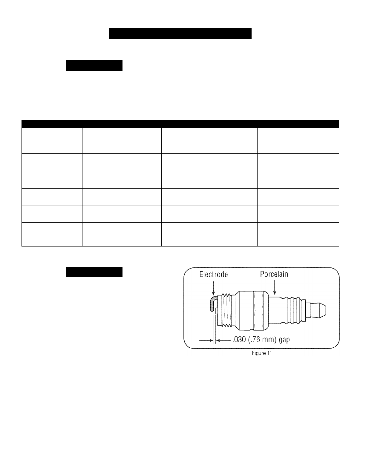
Checking the Spark Plug
Clean spark plug and reset the electrode gap to 0.030” at least once a
season; replace every 100 hours of operation.
Clean area around the spark plug base. Do not sandblast spark
plug. Spark plug should be cleaned by scraping or wire brushing
and washing with a commercial solvent.
Remove and inspect the spark plug. Check gap to make sure it is
set at .030”. See Figure 11.
Replace the spark plug it electrodes are pitted, burned, or the
porcelain is cracked.
14
Page 15
SERVICE AND MAINTENANCE
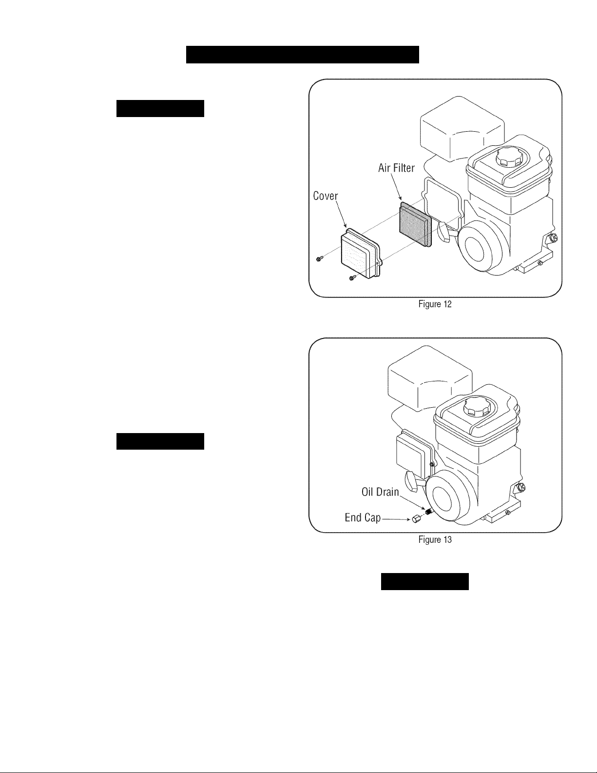
Servicing the Air Cleaner
A CAUTION
Do not use pressurized air or solvents to clean the air cleaner
cartridge.
The air cleaner prevents damaging dirt, dust, etc., from entering the
carburetor and being forced into the engine and is important to engine
life and performance. Never run the engine without an air cleaner
completely assembled.
Replace the air cleaner every 25 hours of operation.
1. Loosen screws that hold the air filter cover.
2. Cpen cover and remove air filter. See Figure 12.
3. Discard old air filter.
4. Install new air filter.
5. Close the cover and tighten screws.
NOTE:
Check Engine Oil
1. Check oil before each use. Stop engine and wait several minutes
2. Remove oil fill dipstick and wipe clean with cloth.
3. Replace and tighten dipstick. Remove and check oil level. Level
4. If needed, add oil slowly - recheck. Do not overfill.
5. Wipe dipstick clean, replace and tighten. Remove and check oil
If the filter is torn or damaged in any way, replace it.
before checking oil level. With engine on level ground, the oil must
be to FULL mark on dipstick.
should be at FULL mark.
level. Cil level should be at FULL line on dipstick.
A CAUTION
Do not overfill. Cverfilling with oil may cause the engine to not start, or
hard starting. If over the FULL mark on the dipstick, drain oil to reduce
oil level to FULL mark on dipstick.
Change Engine Oil
• Only use high quality detergent oil rated with API service
classification SF, SG, or SH. Select the oil's SAE viscosity grade
according to the expected operating temperature. Refer to opera
tion section for viscosity chart.
• Change engine oil after the first five to eight hours of operation,
and every fifty hours or every season thereafter. Change oil every
twenty five hours when operating engine under heavy load or in
high temperatures.
To Drain Oil
1. Drain the fuel from the tank by running the engine until the fuel
tank Is empty.
2. With engine CFF but still warm, disconnect spark plug wire and
keep it away from spark plug.
Used oil is a hazardous waste product. Dispose of used oil properly.
Do not discard with household waste. Check with your local authori
ties or Sears Service Center for safe disposal/recycling facilities.
4. Replace and tighten the oil drain end cap.
5. When engine is drained of all oil, place engine level. Refill with
6. Replace spark plug wire before starting.
Remove oil drain end cap located at the base of the engine, and
drain oil into an appropriate receptacle. See Figure 13.
A CAUTION
approximately 28 oz. of fresh oil. Fill to FULL line on dipstick.
Do not overfill. Refer to Check Engine Oil in this SERVICE &
MAINTENANCE section.
15
Page 16
SERVICE AND MAINTENANCE
Service Muffler
Awarning
Temperature of muffler and nearby areas may exceed 150° F (65°C).
Avoid these areas.
• Inspect muffler every 50 hours, and replace if necessary.
Replacement parts for the muffler must be the same and installed
in the same position as the original parts.
Clean Engine
• Daily or before every use, clean grass, chaff or accumulated
debris from engine. Keep linkage, spring, and controls clean.
Keep area around and behind muffler free of any combustible
debris.
• Keeping engine clean allows air movement around engine.
• Engine parts should be kept clean to reduce the risk of overheat
ing and ignition of accumulated debris.
A CAUTION
Do not use water to clean engine parts. Water could contaminate fuel
system. Use a brush or dry cloth.
Carburetor Adjustment
The carburetor on this engine is not adjustable.
Before performing any type of maintenance on the machine, wait for
all parts to stop moving and disconnect the spark plug wire. Failure
to follow this instruction could result in personal injury or property
damage.
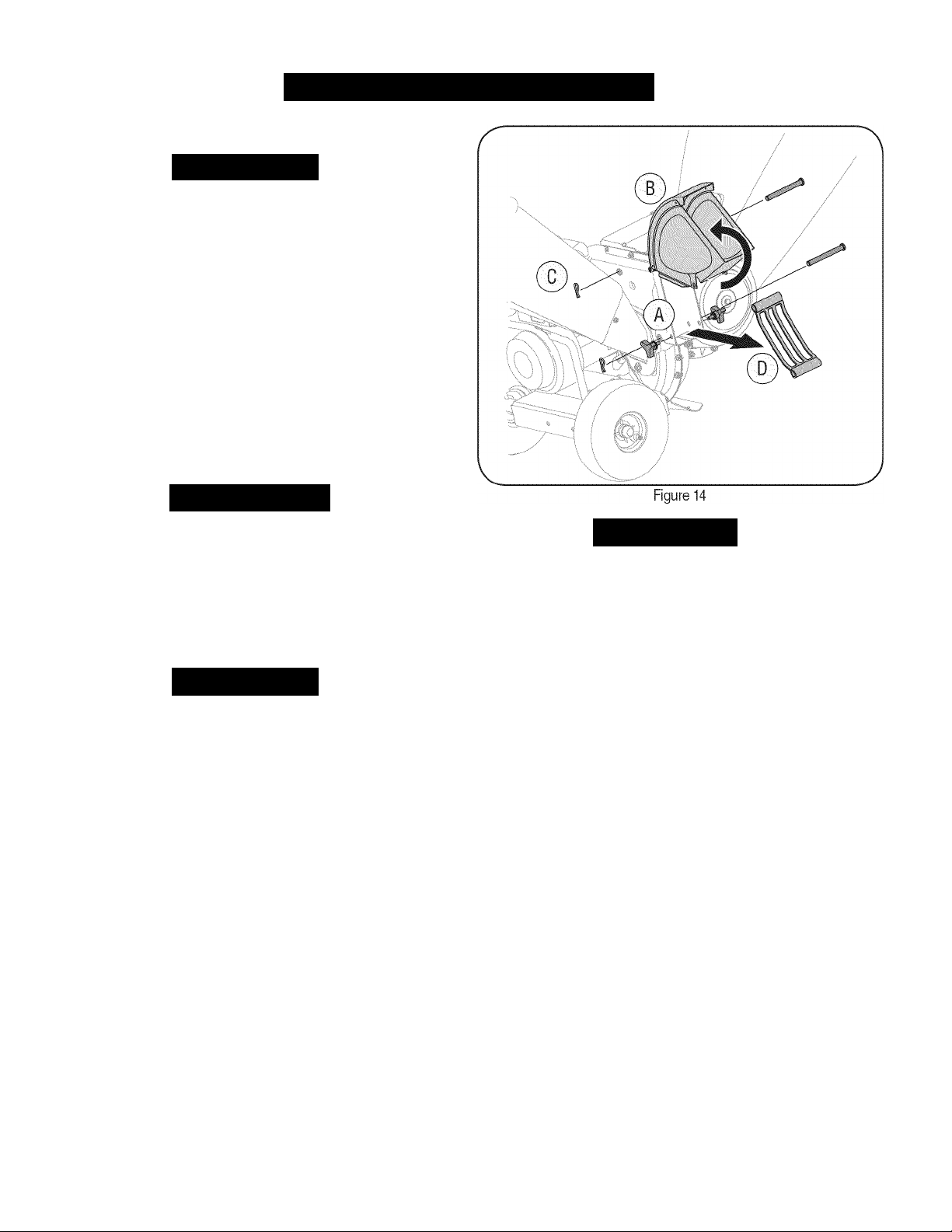
REMOVING THE FLAIL SCREEN
Awarning
Do not attempt to alter the engine speed by tampering with the
engine's governor linkage. Doing so could result in serious personal
injury and damage to the engine. The engine RPM has been set at
the factory.
Engine Speed
If the discharge area becomes clogged, remove the flail screen and
clean area as follows:
1. Stop the engine. Make certain the chipper shredder has come to
2. Disconnect spark plug wire from spark plug and ground against
3. A. Remove the bag and two wing knobs on each side of the chute
LUBRICATION
• Hopper Assembly-
assembly with light oil once a season.
• Discharge Chute-
chute with light oil once a season.
• Release Rod-
once a season.
CLEAN EQUIPMENT
• Clean the chipper shredder thoroughly after each use.
• Wash bag periodically with water. Allow to dry thoroughly in
shade.
• If the flail screen becomes clogged, remove and clean as
instructed below.
NOTE: Cleaning with a forceful spray of water is not recommended as
it could contaminate the fuel system.
Lubricate the pivot points on the hopper
Lubricate the pivot points on the discharge
Lubricate the release rod and spring with light oil
4. Reinstall the screen, making certain to reassemble the flail screen
with the curve side down.
5. Reattach the chute deflector with the hardware previously removed
and connect the bag to unit.
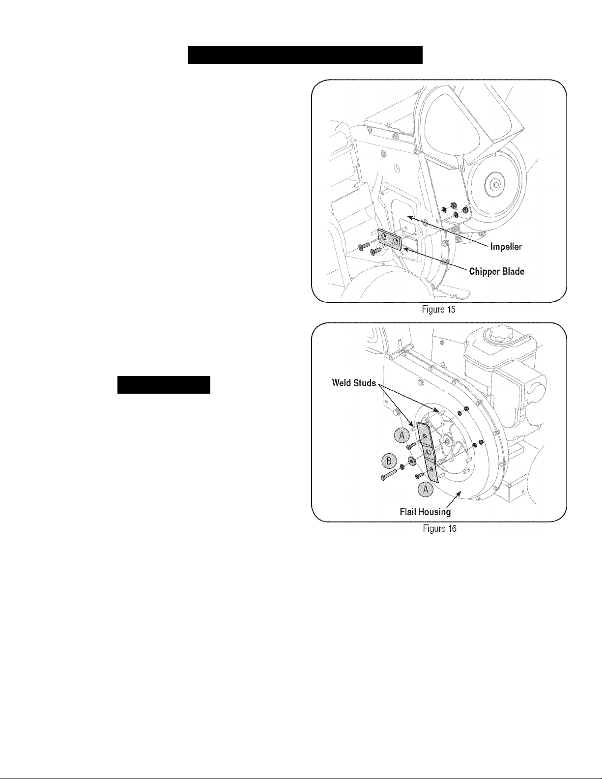
SHARPENING OR REPLACING CHIPPER BLADES
1. Disconnect the spark plug wire and ground against the engine.
2. Remove the flail screen as instructed in the previous section.
3. Remove the chipper chute by removing three hex nuts and
Awarning
a complete stop.
the engine.
deflector. See Figure 14.
B. Lift the chute deflector up to keep it out of the way.
C. Remove the two hairpin clips from each clevis pin which
extend through the housing and remove pins.
D. Remove the flail screen from inside the housing and clean the
screen by scraping or washing with water. See Figure 14.
washers.
16
Page 17
SERVICE AND MAINTENANCE
4. Remove the chipper chute support brace from the frame by
removing the hex bolts.
5. Rotate impeller assembly by hand until you locate one of two
chipper blades in the chipper chute opening.
6. Remove the blade by removing the internal hex screws, lock
washers, and hex nuts which secure it to the impeller. Retain the
hardware. See Figure 15.
NOTE:
and a 1/2” box (or socket) wrench on the inside of the impeller. Hold
the Allen wrench stationary and rotate the box (or socket) wrench to
loosen the nut.
7. Install a replacement blade (Part No. 742-0544) with the hardware
IMPORTANT:
gloves. Follow the original angle of grind and make sure to remove an
equal amount from each blade.
8. To replace the other blade, rotate the impeller to expose the
NOTE:
facing the same direction as when removed. Torque hardware to 250
-300 in. lbs.
Use a 3/16” hex key (Allen) wrench on the outside of the blade
removed earlier or sharpen and replace existing blade.
When sharpening the blade, protect hands by using
second blade and repeat the steps above.
Make certain blades are reassembled with the sharp edge
Awarning
The impeller’s chipper blades and shredder blade are sharp. Wear
leather work gloves to protect your hands.
SHARPENING OR REPLACING THE SHREDDER BLADE
1. Stop the engine and make certain that all moving parts have
come to a complete stop.
2. Disconnect the spark plug wire and ground against the engine.
3. Lower the hopper assembly and place a block under the flail housing.
4. Remove the six hex lock nuts and flat washers from the weld
studs on the flail housing. Retain the hardware.
5. Carefully separate the hopper assembly from the impeller as
sembly and remove the shredder plate. The shredder plate can be
identified by referring to item 29 in the parts list on page 20 & 21.
IMPORTANT:
bolt to between 550 and 700 in.-lbs. and the two outside bolts to
between 250 and 350 in.-lbs.
When reassembling the shredder blade, tighten center
NOTE:
embossed tab faces inward towards the impeller.
6. Remove the two wing knobs that secure the chute deflector and
7.
8.
When reassembling the shredder plate, make certain the
raise the chute.
Insert a 1/2” or 3/4” diameter pipe through the flail screen into the
impeller to keep it from turning or remove the flail screen and
insert a piece of wood into the chute opening.
A. Remove the two internal hex screws, lock washers, and hex
lock nuts which secure the shredder blade to the impeller.
B. Remove the hex bolt, lock washer, and flat washer to
completely free shredder blade. See Figure 16.
Install a replacement blade (Part No. 742-0544) with the hardware
removed earlier or sharpen and replace existing blade.
NOTE:
shredder blade and a 1/2” box (or socket) wrench on the inside of the
shredder blade. Hold the Allen wrench stationary and rotate the box
(or socket) wrench to loosen the nut. Use caution when removing the
blade to avoid contacting the weld studs on housing.
IMPORTANT:
of grind as a guide. It is extremely important that each cutting edge
receives an equal amount of grinding to prevent an unbalanced blade.
An unbalanced blade will cause excessive vibration when rotating at
high speeds and may cause damage to the unit. The blade can be
tested by balancing it on a screwdriver or nail. Remove metal from the
heavy side until it is balanced evenly.
17
Use a 3/16” hex key (Allen) wrench on the outside of the
When sharpening the blade, follow the original angle
Page 18

OFF-SEASON STORAG
Awarning
Never store chipper shredder with fuel in tank indoors or in poorly
ventilated areas where fuel fumes may reach an open flame, spark,
or pilot light as on a furnace, water heater, clothes dryer, or gas
appliance.
I
PREPARING THE ENGINE
For engines stored over 30 days:
1. To prevent gum from forming in fuel system or on carburetor
parts, run engine until it stops from lack of fuel or add a gasoline
additive to the gas in the tank. If you use a gas additive, run the
engine for several minutes to circulate the additive through the
carburetor—after which the engine and fuel can be stored up to
six months.
While engine is still warm, change the oil. See Change Engine Oil
2.
in SERVICE AND MAINTENANCE section.
Remove spark plug and pour approximately 1 oz. (30 ml) of clean
3.
engine oil into the cylinder. Pull the recoil starter several times to
distribute the oil, and reinstall the spark plug.
Clean engine of surface debris.
PREPARING THE CHIPPER SHREDDER
• When storing the chipper shredder in an unventilated or metal
storage shed, care should be taken to rustproof the non-painted
surfaces. Using a light oil or silicone, coat the equipment,
especially any springs, bearings, and cables.
• Remove all dirt from exterior of engine and equipment.
• Follow lubrication recommendations.
• Store equipment in a clean, dry area. Do not store next to
corrosive materials, such as fertilizer. Do not store in an area
where equipment is present that may use a pilot light or has a
component that can create a spark.
18
Page 19

TROUBLESHOOTING
Awarning
Before performing any type of maintenance/service, disengage all
controls and stop the engine. Wait until all moving parts have come to
a complete stop. Disconnect spark plug wire and ground it against the
engine
to prevent unintended starting. Always wear safety glasses during
operation or while performing any adjustments or repairs.
I
Problem
Engine fails to start
Engine runs erratically
Engine overheats
Engine hesitates at high RPMs1.Spark plug gap set too close
Engine idles poorly
Excessive vibration
Unit does not discharge
Rate of discharge slows
considerably or composition of
discharged material changes
1.
Throttle lever
2.
Choke not in the CHOKE position
3.
Spark plug wire disconnected
4.
Faulty spark plug
5.
Fuel tank empty or stale fuel
6.
Cannot pull recoil cord
7.
Engine flooded
1.
Unit running on CHOKE
2.
Spark plug wire loose
3.
Stale fuel
4.
Water or dirt in fuel system
5.
Dirty air cleaner
6.
Low engine RPM
7.
Carburetor out of adjustment
1.
Engine oil level low
2.
Airflow restricted
1.
Fouled spark plug
2.
Dirty air cleaner
1.
Loose parts or damaged impeller
1.
Chute deflector clogged
2.
Foreign object lodged in impeller
3.
Low engine RPM
1.
Low engine RPM
2.
Chipper blade dull
Cause Remedy
not
in correct starting position
1.
Move throttle lever to START/RUN position.
2.
Move CHOKE to the CHOKE position.
3.
Connect wire to spark plug.
4.
Clean, adjust gap, or replace.
5.
Fill tank with clean, fresh gasoline.
6.
Obstruction lodged in impeller. Disconnect spark
plug wire and remove lodged object.
7.
Wait a tew minutes to restart.
1.
Move choke lever to the RUN position.
2.
Connect and tighten spark plug wire.
3.
Fill tank with fresh gasoline.
4.
Refill with fresh fuel.
5.
Clean or replace air cleaner filter.
6.
Always run engine at full throttle.
7.
Contact your Sears Parts & Repair Center.
1.
Fill engine with proper amount and type of oil.
2.
Clean debris from around the engine’s cooling fins
and blower housing.
1.
Remove spark plug and adjust gap.
1.
Replace spark plug and adjust gap.
2.
Replace air cleaner cartridge.
1.
Stop engine immediately and disconnect spark plug
wire. Contact your Sears Parts & Repair Center.
1.
Stop engine immediately and disconnect spark
plug wire. Clean flail screen and inside of discharge
opening.
2.
Stop engine and disconnect spark plug wire.
Remove lodged object.
3.
Always run engine at full throttle.
1.
Always run engine at full throttle.
2.
Replace or sharpen chipper blade or contact your
Sears Parts & Repair Center.
NEED MORE HELP?
i'll find the answer and more on managemyhome.cotn - for free!
» Find this and all your other product manuals online.
» Get answers from our team of home experts.
» Get a personalized maintenance plan for your home.
* Find information and tools to help with home projects.
Page 20

PARTS LIS
Craftsman Chipper Shredder — Model No. 247.77638
I
10)
Page 21

PARTS LIS
Craftsman Chipper Shredder — Model No. 247.77638
I
J
Ref. No. Part No. Description
1.
936-0217 Lock Washer, 3/8
2.
914-0149B Cotter
3.
720-0170 Wing Knob 5/16-18
4.
681-0094-0721 Chute Deflector Assembly
5.
911-0835 Clevis Pin
6.
781-0457-0637 Shredder Screen
7. 926-0211 U-Nut 5/16-18
8.
950-0793 Spacer
9.
912-3027 Hex Lock Nut, 1/4-20
10.
712-3004A Hex Lock Nut 5/16-18
11. 936-0119 Lock Washer 5/16
12.
681-0117-0721 Inner Impeller Housing Assembly
13.
710-3025 Hex Cap Screw 5/16-18 x.625
14.
710-0157 Hex Cap Screw 5/16-24 x .75
15.
942-0544 Chipper Blade
16.
710-1054 Hex Cap Screw 5/16-24 x 1.0
17. 681-04095 Impeller Assembly
18. 912-0411 Hex Lock Nut 5/16-24
19.
712-0266A Nut, Jam Lock, 3/8-16
20.
719-04308 Flail Blade
21.
738-04286 Shoulder Pin, .5 x 2.625
Pin
Ref. No. Part No. Description
22.
710-3008 Hex Cap Screw 5/16-18 x .75
23. 736-0247 Flat Washer 3/8 X 1.25
24. 942-0571 Shredder Blade
25. 710-1254 Hex Cap Screw 3/8-24 x 2.25
26. 681-0004A-0721 Outer Impeller Housing Assembly
27. 710-0825 Hex Cap Screw 1/4-20 x 3.75
28. 781-0515-0637 Front Support Bracket
29. 781-0574-0637 Shredder Plate
30. 681-0104-0721 Rear Hopper Bracket Assembly
31. 932-0306A Compression Spring 1.75
32. 936-0117 Flat Washer
33. 914-0104 Cotter Pin
34. 936-0264 Flat Washer.330 ID x .630 OD
35. 710-0376 Hex Cap Screw 5/16-18 x 1.0
36. 748-0453 Spacer, .375 ID x 2.50 LG
37. 731-1707A Hopper Assembly
38. 912-0429 Hex Lock Nut 5/16-18
39. 731-171OA Hopper Collar
40. 681-0123-0721 Front Hopper Bracket Assembly
41. 711-1128 Lock Rod
21
Page 22

PARTS LIS
Craftsman Chipper Shredder — Model No. 247.77638
I
22
Page 23

PARTS LIS
Craftsman Chipper Shredder — Model No. 247.77638
I
J
Ref. No. Part No. Description
1 728-0175 Pop Rivet
2 753-05094 Chipper Shredder Chute
3 735-0249A Chute Flap
4 781-0633 Chute Flap Strip
5 681-0068A-0637 Chipper Chute Assembly
6 710-0751 Hex Cap Screw 1/4 -20 x.620
7 712-04064 Hex Lock Nut 1/4-20
8 710-0106 Hex Cap Screw 1/4-20 x 1.25
9 736-0173 Flat Washer .28 ID x .74 OD
10 736-0242 Bell Washer .340 ID x .872 OD
11 912-3010 Hex Nut 5/16-18
12 749-1004-0721 Support Brace
13 712-3004A Hex Lock Nut 5/16-18
14 710-3180 Hex Cap Screw 5/16-18 x 1.75
Ref. N- Part No. Description
15 936-0170 Bell Washer 5/16 x 1.0
16 950-0786 Spacer
17 738-0813 Axle Assembly
18 737-0298 Pipe, Oil Drain
19 634-04009 Wheel Complete, 10.0 x 4.0 Gray
20 726-0214 Push Cap
21 681-0183B-0721 Frame
22 936-0451 Washer,.320 ID x.93 OD
23 710-0502A Screw, 3/8-16x1.250
24 723-0400 Safety Glasses (Not Shown)
25 964-04024 Chipper Bag Ass'y (Not Shown)
26 737-0132 Oil Drain End Cap
27 731-1617 Tamper
Page 24

PARTS LIST
Craftsman Engine Model 204312-0529 For Chipper Shredder Model No. 247.77638
1058 OPERATOR’S MANUAL 48 SHORT BLOCK
306
1 1329 REPLACEMENT ENGINE |
529
I
1330 REPAIR MANUAL
46
227
562
615
616
278
rf
505
16
146
741
307
219
220
24
746 :
742 '•
12
^77
i 3
/
552
415
1194
718
998 «T;
1427
%
15
718A
|27‘'
28
18
21 12
20
22
27
32
30
358 ENGINE GASKET SET
'7
21
24
Page 25

PARTS LIST
Craftsman Engine Model 204312-0529 For Chipper Shredder Model No. 247.77638
J
33
/3-
l\v>
'1 /
.......
.....
7==--*®
45
42
i. 7.
Xry j
\l7"
35
36
1026
7
'■ '\
883\ o(
/..'
1029
I
192
'ùim ^
13
1023
I 1022
^(9x0^
337
635 1
1095 VALVE GASKET SET
914
383,
11
663«^
281
663A_
632
209
211
7 \
222
190
504 i
621
1138
773
271A ,
668
(or
1022 \\
188
188
410
265 r$
267
Page 26

PARTS LIST
Craftsman Engine Model 204312-0529 For Chipper Shredder Model No. 247.77638
121 CARBURETOR OVERHAUL KIT
'
.....
127 (0
98
I
832
53
163
118
(0^''
161
'l«S- , 445
104 ‘
105
117
122 51A S*,
5l\U
11
967
i"'
137
163 ®
633 ©
300
613A@:p
81
'Y
if
836
U
972A
957 fc
^
...
y
■ K
187
■\ 601
240
'iiji
1
190
26
Page 27

PARTS LIST
Craftsman Engine Model 204312-0529 For Chipper Shredder Model No. 247.77638
I
...
......................................
304
37
78
I
363
J
356
356A •<*'
356B
356C
774 f
■Qi>
608
597
60
59
58
456
305
635 ^
689 (
....^.......
/1
459^
1005
455
1070
334
333
851 ir
¡9
1210 ,
332
'Y--'
W
1211
592 #
55
III
65
Page 28

PARTS LIST
Craftsman Engine Model 204312-0529 For Chipper Shredder Model No. 247.77638
Ref. No. Part No. Description
1 794849 Cyiinder Assembiy
2 698340 Kit-Bushing/Seai (Magneto Side)
3 391086s* Seal-Oii (Magneto Side)
5 794870 Head-Cyiinder
7 694872 •+ Gasket-Cyiinder Head
11 696796 Tube-Breather
12 694953 • Gasket-Crankcase
13 794829 Screw (Cyiinder Head)
15 697757 Plug-Oii Drain
16 794874 Crankshaft
18 791965 Cover-Crankcase
19 698340 Kit-Bushing/Seal (PTO Side)
20 391086s* Seal-Oii (PTO Side)
21 281658s Cap-Oil Fill
22 794825 Screw (Crankcase Cover/Sump)
23 794814 Flywheel
24 222698s Key-Flywheel
25 792117 Piston Assembly (Standard)
792144 Piston Assembly (.020” Oversize)
26 793561 Ring Set (Standard)
792073 Ring Set (.020” Oversize)
27 690975 Lock-Piston Pin
28 696581 Pin-Piston
29 691691 Rod-Connecting
30 694692 Dipper-Connecting Rod
32 690976 Screw (Connecting Rod)
33 499596 Valve-Exhaust
34 792200 Valve-Intake
35 694865 Spring-Valve (Intake)
36 694865 Spring-Valve (Exhaust)
37 790730 Guard-Flywheel
42 499586 Keeper-Valve
45 690977 Tappet-Valve
46 790958 Camshaft
48 N/A Short Block
Ref. No. Part No. Description
51 694874
51A 694875
53 794830 Stud (Carburetor)
55 695288 Housing-Rewind Starter
58 693389 Rope-Starter
59 805957 Insert-Grip
60 490652 Grip-Starter Rope
65 699228 Screw (Rewind Starter)
78 795026 Screw (Flywheel Guard)
81 794817 Lock-Muffler Screw
95 690718 Screw (Throttle Valve)
97 696387 Shaft-Throttle
98 695408 0 Kit-Idle Speed
104 694918 0 Pin-Float Hinge
105 696136 0 Valve-Float Needle
108 696143 Valve-Choke
109 790149 Shaft-Choke
117 696134 Jet-Main (Std.) (IncI 0-Ring Seal)
118 696135 Jet-Main (High Alt.) (IncI 0-Ring Seal)
121 696146 Kit-Carburetor Cverhaul
122 694876 Spacer-Carburetor
125 699966 Carburetor
127 690727 0 Plug-Welch
130 696139 Valve-Throttle
133 694914 Float-Carburetor
135 696142 Tube-Fuel Transfer
137 695426 0 Gasket-Float Bowl
141 696145 Kit-Choke Shaft
146 690979 Key-Timing
161 794768 Base-Air Cleaner
163 692277 0* Gasket-Air Cleaner
187 791766 Line-Fuel (Cut To Required Length)
188 699479 Screw (Control Bracket)
190 699220 Screw (Fuel Tank)
192 690083 Adjuster-Rocker Arm
0*+
0*+
Gasket-Intake
Gasket-Intake
28
Page 29

PARTS LIST
Craftsman Engine Model 204312-0529 For Chipper Shredder Model No. 247.77638
J
Ref. No. Part No. Description
209 694867 Spring-Governor (Red)
211 695307 Spring-Governed Idle
219 693578 Gear-Governor
220 691724 Washer (Governor Gear)
222 794799 Bracket-Control
227 694864 Lever-Governor Control
240 298090s Filter-Fuel
265 691024 Clamp-Casing
267 699492 Screw (Casing Clamp)
271 695381 Lever-Control
278 792008 Washer (Governor Control Lever)
281 697268 Panel-Control
300 794806 Muffler
304 791478
305 699480 Screw (Blower Housing)
306 697240 Shield-Cylinder
307 794822 Screw (Cylinder Shield)
332 794824 Nut (Flywheel)
333 492341 Armature-Magneto
334 699477 Screw (Magneto Armature)
337 491055s Plug-Spark
356 692603 Wire-Stop
356A 692390 Wire-Stop
356B 695815 Wire-Stop
356C 695295 Wire-Stop
358 695438 Gasket Set-Engine
363 19203 Puller-Flywheel
369 695422 Spring-Float Bowl
383 19374s Wrench-Spark Plug
410 695382 Link-Control
415 691363 Plug (Cylinder)
425 794835 Screw (Air Cleaner Cover)
445 491588s Filter-Air Cleaner Cartridge
446 794941 Spring-Retainer
455 794867 Cup-Flywheel
Housing-Blower
Ref. No. Part No. Description
456 692299 Plate-Pawl Friction
459 281505s Pawl-Ratchet
493 691177 Bracket-Mounting
504 695383 Washer Set-Friction
505 691251 Nut (Governor Control Lever)
529 791822 Grommet (Cylinder)
552 694674 Bushing-Governor Crank
562 793216 Bolt (Governor Control Lever)
592 690800 Nut (Rewind Starter)
597 691696 Screw (Pawl Friction Plate)
601 791850 Hose-Clamp
608 695287 Starter-Rewind
613 794846 Screw (Muffler)
613A 794848 Screw (Muffler)
615 694676 Retainer-Governor Shaft
616 694675 Crank-Governor
621 692310 Switch-Stop
632 695917 Spring/Link-Mechanical Governor
633 0 690998 Seal-Choke/Throttle Shaft
635 691909 Boot-Spark Plug
663 699492 Screw (Control Panel)
663A 795026 Screw (Control Panel)
668 694257 Spacer (Control Bracket)
689 691855 Spring-Friction
718 690959 Pin-Locating (Cylinder)
718A 695178 Pin-Locating (Cylinder Head)
741 691288 Gear-Timing
742 692564 Retainer-E Ring
746 694679 Gear-Idler
773 694258 Retainer
774 695447 Screw (Stop Wire)
798 697890 Screw (Rocker Arm)
832 795035 Guard-Muffler
836 794845 Screw (Muffler Guard)
836A 710023 Screw (Muffler Guard)
29
Page 30

PARTS LIST
Craftsman Engine Model 204312-0529 For Chipper Shredder Model No. 247.77638
Ref. No. Part No. Description
851 692424 Terminal-Spark Plug
868 690968•+ Seal-Valve
883 794818* Gasket-Exhaust
914 794827 Screw (Rocker Cover)
951 699961 Lever-Choke
957 792647 Cap-Fuel Tank
967 491435s Filter-Pre Cleaner
968 794785 Cover-Air Cleaner
972 694260 Tank-Fuel
975 696138 Bowl-Float
998 696683 Pipe-Oil
1005 794815 Fan-Flywheel
1022 690971•+ Gasket-Rocker Cover
1023 697691 Cover-Rocker
1026 695177 Rod-Push
1029 690972 Arm-Rocker
1036 Label-Emissions
1058 MS3797 Operator’s Manual
1070 794821 Screw (Flywheel Fan)
1095 695440 Gasket Set-Valve
1100 791959 Pivot-Rocker Arm
1127 695407 Screw (Float Bowl)
1138 694255 Nut (Control Bracket)
1194 691876 Seal-0 Ring (Plug)
1210 498144 Pulley/Spring Assembly (Pulley)
1211 498144 Pulley/Spring Assembly (Spring)
1329 2043120536e9 Replacement Engine
1330 272147 Repair Manual
1427 695757 Cap-Pipe
I
• Included
0 Included in Carburetor Overhaul Kit, Key Number 121
+ Included in Valve Gasket Set, Key Number 1095
in
Engine Gasket Set, Key Number 358
30
Page 31

Craftsman Chipper Shredder Model No. 247.77638
Parts Li
L
J
777S33113 777S33200
“ROTATING CUTTING BLADES. KEEP HANDS AND
FEET OUT OF OPENING WHILE MACHINE IS
RUNNING.
•DO NOT OPERATE THIS MACHINE UNLESS THE
CHUTE DEFLECTOR HAS BEEN PROPERLY
INSTALLED AND IS SECURED WITH THE HAND
KNOBS.
777S30185
0 NOT DEPOSIT
ATERIAL LARGER THAN
1/2" DIAMETER IN LARGE
SHREDDER HOPPER.
THIS MAY DAMAGE
MACHINE.
777S30181
Operation Of This Equipment May Create
Sparks That Can Start Fires Around Dry
Vegetation. A Spark Arrestor May Be
Required. The Operator Should Contact
Local Fire Agencies For Laws Or Regula
tions To Fire Prevention Requirements.
777X43688
DOiOT
USE E85 0RFUEL
CONTAMiG MORE
THA110% ETHAiOL
777S32036
TO AVOID SERIOUS INJURY:
' Read the operator's manual(s) before starting and
using unit.
’ Keep all shields and guards in place and securely
attached.
' Keep hands, feet, face, clothing and long hair out of
Shredder Hopper, Chipper Chute and Discharge
Chute while the engine is running. Rotating cutting
blades inside these openings will cause serious
personal injury if contacted. Material being processed
may bounce back from inlet openings or be thrown
from the discharge chute. Long hair or loose clothing
may be pulled or sucked into the inlet openings.
' Do not place branches over 1/2 inch diameter into
the large Shredder Hopper. Branches over 1/2 inch in
diameter should be placed in the Small Chipper
Chute.
' If the chipped shredder jams or becomes clogged,
immediately shut off the engine and wait for all
moving parts to come to a complete stop before
clearing.
' Do not install, remove, adjust, or service the
discharge screen or any other part while the engine
is running. Blade contact can occur.
ROTATING CUTTING BLADES.
KEEP HANDS AND FEET OUT
OF OPENINGS WHILE MACHINE
IS RUNNING.
777S32282
I DO NOT OPERATE THIS MACHINE
I UNLESS THE CHUTE DEFLECTOR
^AS BEEN PROPERLY INSTALLED.
5
ÄJ
777D12676
3-WAY CHIPPER SHREDDER
HARDENED STEEL CHRDMIUM CHIPPER BLADES
10:1 REDUCTIDN RATID
777S32037
•
TO AVOID SERIOUS INJURY:
* Do not operate on uneven ground where unit is
unstable. Do not operate on pavement, gravel or
other hard surfaces since objects can ricochet
and cause injury.
* To avoid a fire hazard, keep leaves, grass, and other
combustible materials away from hot engine and
muffler.
• Keep children and others away from area of
operation.
• Wear approved safety glasses, gloves and ear
protection.
31
Page 32

(This page applicable in the U.S.A. and Canada only.)
Sears, Roebuck and Co., U.S.A. (Sears), the California Air Resources Board (CARB)
and the United States Environmental Protection Agency (U.S. EPA)
Emission Control System Warranty Statement (Owner’s Defect Warranty Rights and Obligations)
EMISSION
PIED ENGINES PURCHASED IN CALIFORNIA IN 1995 AND THEREAF- ELSEWHERE IN THE UNITED STATES (AND AFTER JANUARY 1,2001 IN
TER, WHICH ARE USED IN CALIFORNIA, AND TO CERTIFIED MODEL CANADA).
CONTROL WARRANTY COVERAGE IS APPLICABLE TO CERTI- YEAR 1997 AND LATER ENGINES WHICH ARE PURCHASED AND USED
California and United States Emission Control Defects Warranty Statement
The California Air Resources Board (CARB), U.S. EPA and Sears are pleased engine for the periods of time listed below, provided there has been no abuse,
to explain the Emission Control System Warranty on your model year 2000 and neglect or improper maintenance of your small off-road engine. Your emislater small off-road engine (SORE). In California, new small off-road engines
must be designed, built and equipped to meet the State’s stringent anti-smog
standards. Elsewhere in the United States, new non-road, spark-ignition
engines certified for model year 1997 and later must meet similar standards set
forth by the U.S. EPA. Sears must warrant the emission control system on your
sion control system includes parts such as the carburetor, air cleaner, ignition
system, muffler and catalytic converter. Also included may be connectors and
other emission related assemblies. Where a warrantable condition exists. Sears
will repair your small off-road engine at no cost to you including diagnosis, parts
and labor.
Sears Emission Control Defects Warranty Coverage
Small off-road engines are warranted relative to emission control parts defects part on your engine is defective, the part will be repaired or replaced by Sears,
for a period of one year, subject to provisions set forth below. If any covered
Owner’s Warranty Responsibilities
As the small off-road engine owner, you are responsible for the performance of
the required maintenance listed in your Operating and Maintenance Instruc
tions. Sears recommends that you retain all your receipts covering maintenance
on your small off-road engine, but Sears cannot deny warranty solely for the
lack of receipts or for your failure to ensure the performance of all scheduled
maintenance. As the small off-road engine owner, you should however be
aware that Sears may deny you warranty coverage if your small off-road engine
or a part has failed due to abuse, neglect, improper maintenance or unap
proved modifications. You are responsible for presenting your small off-road
engine to an Authorized Sears Service Dealer as soon as a problem exists. The
undisputed warranty repairs should be completed in a reasonable amount of
time, not to exceed 30 days. If you have any questions regarding your warranty
rights and responsibilities, you should contact a Sears Service Representative
at 1 -800-469-4663. The emission warranty is a defects warranty. Defects are
judged on normal engine performance. The warranty is not related to an in-use
emission test.
Sears Emission Control Defects Warranty Provisions
The following are specific provisions relative to your Emission Control Defects Warranty Coverage. It is in addition to the Sears engine warranty for non-regulated
engines found in the Operating and Maintenance Instructions.
1. Warranted Parts
Coverage under this warranty extends only to the parts listed below (the
emission control systems parts) to the extent these parts were present on
the engine purchased.
a. Fuel Metering System
• Cold start enrichment system
• Carburetor and internal parts
• Fuel Pump
b. Air Induction System
•Air cleaner
• Intake manifold
c. Ignition System
• Spark plug(s)
• Magneto ignition system
d. Catalyst System
• Catalytic converter
• Exhaust manifold
• Air injection system or pulse valve
e. Miscellaneous Items Used in Above Systems
• Vacuum, temperature, position, time sensitive valves
and switches
• Connectors and assemblies
2. Length of Coverage
Sears warrants to the initial owner and each subsequent purchaser that
the Warranted Parts shall be free from defects in materials and workman
ship which caused the failure of the Warranted Parts for a period of one
year from the date the engine is delivered to a retail purchaser.
In the USA and Canada, a 24 hour hot line, 1-800-469-4663, has a menu of pre-recorded messages offering you engine maintenance information.
No Charge
Repair or replacement of any Warranted Part will be performed at no
charge to the owner, including diagnostic labor which leads to the
determination that a Warranted Part is defective, if the diagnostic work is
performed at an Authorized Sears Service Dealer. For emissions warranty
service contact your nearest Authorized Sears Service Dealer as listed in
the “Yellow Pages” under “Engines, Gasoline,” “Gasoline Engines,” “Lawn
Mowers,” or similar category.
Claims and Coverage Exclusions
Warranty claims shall be filed in accordance with the provisions of the
Sears Engine Warranty Policy. Warranty coverage shall be excluded for
failures of Warranted Parts which are not original Sears parts or because
of abuse, neglect or improper maintenance as set forth in the Sears
Engine Warranty Policy. Sears is not liable to cover failures of Warranted
Parts caused by the use of add-on, non-original, or modified parts.
Maintenance
Any Warranted Part which is not scheduled for replacement as required
maintenance or which is scheduled only for regular inspection to the effect
of “repair or replace as necessary” shall be warranted as to defects for the
warranty period. Any Warranted Part which is scheduled for replacement
as required maintenance shall be warranted as to defects only for the
period of time up to the first scheduled replacement for that part. Any
replacement part that is equivalent in performance and durability may
be used in the performance of any maintenance or repairs. The owner is
responsible for the performance of all required maintenance, as defined in
the Sears Operating and Maintenance Instructions.
Consequential Coverage
Coverage hereunder shall extend to the failure of any engine components
caused by the failure of any Warranted Part still under warranty.
GDOC-100188 Rev. A
32
Page 33

Look For Relevant Emissions Dorabiiity Period and
Air Index Information On Your Engine Emissions Label
Engines that are certified to meet the California Air Resources Board (GARB) Tier 2 Emission Standards must
display information regarding the Emissions Durability Period and the Air Index. Sears, Roebuck and Co., U.S.A.
makes this information available to the consumer on our emission labels.
The Emissions Durability Period describes the number of hours of actual running time for which the engine is
certified to be emissions compliant, assuming proper maintenance in accordance with the Operating & Mainte
nance Instructions. The following categories are used:
Moderate: Engine is certified to be emission compliant for 125 hours of actual engine running time.
Intermediate: Engine is certified to be emission compliant for
Extended: Engine is certified to be emission compliant for 500 hours of actual engine running time.
For example, a typical walk-behind lawn mower is used 20 to 25 hours per year. Therefore, the Emissions
Durability Period of an engine with an intermediate rating would equate to 10 to 12 years.
The Air Index is a calculated number describing the relative level of emissions for a specific engine family. The
lower the Air Index, the cleaner the engine. This information is displayed in graphical form on the emissions label.
250
hours of actual engine running time.
After July 1,2000, Look For Emissions Compliance Period
On Engine Emissions Compliance Label
After July 1, 2000 certain Sears, Roebuck and Co., U.S.A. engines will be certified to meet the United States
Environmental Protection Agency (USEPA) Phase 2 emission standards. For Phase 2 certified engines, the Emis
sions Compliance Period referred to on the Emissions Compliance label indicates the number of operating hours
for which the engine has been shown to meet Federal emission requirements.
For engines less than 225 cc displacement. Category C = 125 hours, B = 250 hours and A = 500 hours.
For engines of 225 cc or more. Category C = 250 hours, B = 500 hours and A = 1000 hours.
This is a generic representation of the emission label typically found on a certified engine.
33
GDOC-100182 Rev. A
Page 34

REPAIR PROTECTION AGREEMENT
Congratulations on making a smart purchase. Your new Craftsman®
product is designed and manufactured for years of dependable opera
tion. But like all products, it may require repair from time to time. That's
when having a Repair Protection Agreement can save you money and
aggravation.
Here’s what the Repair Protection Agreement* includes:
• Expert service
• Unlimited service and no charge
covered repairs
• Product replacement
fixed
• Discount of 10%
parts not covered by the agreement; also, 10% off regular price of
preventive maintenance check
• Fast help by phone
from a Sears representative. Think of us as a “talking owner’s
manual.”
by our 10,000 professional repair specialists
for parts and labor on all
up to $1500 it your covered product can’t be
from regular price of service and related installed
- we call it Rapid Resolution - phone support
Once you purchase the Agreement, a simple phone call is all that it
takes for you to schedule service. You can call anytime day or night, or
schedule a service appointment online.
The Repair Protection Agreement is a risk-free purchase. If you cancel
for any reason during the product warranty period, we will provide a full
refund. Or, a prorated refund anytime after the product warranty period
expires. Purchase your Repair Protection Agreement today!
Some limitations and exclusions apply. For prices and additional
information in the U.S.A. call 1-800-827-6655.
‘Coverage in Canada varies on some items. For full details call
Sears Canada at 1-800-361-6665.
Sears Installation Service
For Sears professional installation of home appliances, garage door
openers, water heaters, and other major home items, in the U.S.A. or
Canada call
1-800-4-MY-HOME®.
34
Page 35

Declaración de garantía.......................Página 35
Prácticas operación seguras
Montaje
Operación
Servicio y Mantenimiento.....................Páginas 46-49
Almacenamiento fuera de temporada.... Página 50
Solución de problemas
................................................
............................................
...............
.......................
Páginas 36-39
Páginas 40-43
Páginas 44-45
Página 51-52
Etiquetas de seguridad........................Página 7
Lista de piezas
Acuerdo de Protección Para
Reparaciones............................................Página 55
Labels.......................................................Página 31
Número de servicio
..........................................
......................
Cubierta posterior
Página 20
GARANTIA
I
CRAFTSMAN TOTAL GARANTIA
Cuando
son
operados y mantenidos de acuerdo con las instrucciones suministradas en su totalidad, si esto no astilladora de fragmentación
debido a un defecto de material o mano de obra dentro de dos años a partir de la fecha de compra, el retorno a cualquier tienda Sears, Sears
partes del Centro de Servicio y Reparación, u otros Artesano salida en los Estados Unidos para la reparación gratuita (si la reparación o la
sustitución resulte imposible.
Esta garantía se aplica sólo para 90 días a partir de la fecha de compra si esta astilladora de fragmentación cada vez es utilizado para propósi
tos comerciales o de alquiler.
Esta garantía sólo cubre defectos de material y mano de obra. Sears no pagará por:
• Esta garantía sólo cubre defectos de material y mano de obra. Sears NO • Los elementos que se desgastan durante el uso normal,
incluyendo pero no limitado a las hojas, la bujía, el aire limpio, mayal pantalla y receptor bolsa.
• Norma de servicios de mantenimiento, cambios de aceite, o afinación.
• Cambio de neumáticos de sustitución o reparación de pinchazos causados por objetos desde el exterior, tales como clavos, espinas,
tocones, o de vidrio.
• Cambio de neumáticos o ruedas de reemplazo o la reparación como consecuencia de desgaste normal, accidente, o de la mala oper
ación o mantenimiento.
• Las reparaciones necesarias debido a los abusos del operador, incluyendo pero no limitado a los daños causados por objetos que
impactan doblar el marco o cigüeñal, o situación de exceso de velocidad del motor.
• Las reparaciones necesarias debido a la negligencia del operador, incluyendo pero no limitado a, productos eléctricos y mecánicos de
los daños causados por almacenamiento inadecuado, falta de utilización de la categoría apropiada y la cantidad de aceite de motor, o el
fracaso para mantener el equipo de acuerdo con las instrucciones contenidas en el manual del operador.
• Motor (sistema de combustible), la limpieza o reparaciones causadas por los combustibles decidida a ser contaminados o oxidado (ran
cio). En general, el combustible debe ser utilizado dentro de los 30 días siguientes a su fecha de compra. Normal desgaste y deterioro de
los acabados exteriores, o la etiqueta del producto de reemplazo
Esta garantía sólo se aplica mientras que este producto está dentro de los Estados Unidos.
Esta garantía le otorga derechos legales específicos, y usted también puede tener otros derechos que varían de estado a estado.
ESPECIFICACIONE
PRODUCTO
Serie:
Tipo de aceite del motor:
Capacidad de aceite del motor:
El combustible:
Bujías:
Separación de las bujías:
§ Sears Brands, LLC
Sears, Roebuck and Co., Hoffman Estates, IL 60179
1450
SAE 30
28 onzas
Gasolina sin Plomo
Champion® RC-12YC
.030”
Número de modelo..........................................................
Número de serie
Fecha de compra.............................................................
Registre arriba el número del modelo, el número de serie y la fecha
..............................................................
de compra
35
Page 36

INSTRUCCIONES DE SEGURIDA
I
A ADVERTENCIA
La presencia de este símbolo indica que se trata de instrucciones
importantes de seguridad que se deben respetar para evitar
poner en peligro su seguridad personal y/o material y la de otras
personas. Lea y siga todas las instrucciones de este manual antes
de poner en funcionamiento esta máquina. Si no respeta estas
instrucciones podría provocar lesiones personales. Cuando vea este
símbolo, ¡preste atención a la advertencia!
Esta máquina fue construida para ser operada de acuerdo con
las reglas de seguridad contenidas en este manual. Al igual que
con cualquier tipo de equipo motorizado, un descuido o error por
parte del operador puede producir lesiones graves. Esta máquina
es capaz de amputar manos y pies y de arrojar objetos con gran
fuerza. De no respetar las instrucciones de seguridad siguientes se
pueden producir lesiones graves o la muerte.
A ADVERTENCIA
PROPOSICIÓN 65 DE CALIFORNIA
El escape del motor de este producto, algunos de sus componentes
y algunos componentes del vehículo contienen o liberan sustancias
químicas que el estado de California considera que pueden producir
cáncer, defectos de nacimiento u otros problemas reproductivos.
CAPACITACION
• Lea, entienda y cumpla todas las instrucciones incluidas en
la máquina y en los manuales antes de montarla y utilizarla.
Guarde este manual en un lugar seguro para consultas futuras y
regulares, así como para solicitar repuestos.
• Lea el Manual del Operador y siga todas las advertencias e
instrucciones de seguridad. El fracaso de hacer así puede causar
la herida seria al operador y/o personas presentes. Para llamada,
de preguntas, 1-800-659-5917.
• Familiarícese con todos los controles y su operación adecuada.
Sepa cómo detener la máquina y cómo desengranar los controles
rápidamente.
• No permita nunca que los niños menores de 16 años utilicen
esta máquina. Los niños de 16 años y más mayores deben
leer y comprender las instrucciones de operación y las reglas
de seguridad contenidas en este manual, y también deben ser
capacitados y estar supervisados por uno de los padres.
• Nunca permita que los adultos operen esta máquina sin recibir
antes la instrucción apropiada.
• Mantenga a los transeúntes, ayudantes, mascotas y niños al
menos a 75 pies de la máquina mientras está operando. Detenga
la máquina si alguien entra en la zona.
• Nunca encienda un motor en espacios cerrados o en una zona
con poca ventilación. El escape del motor contiene monóxido de
carbono, un gas inodoro y letal.
• No ponga las manos o los pies cerca de las piezas rotatorias o
en las cámaras de alimentación ni en la abertura de descarga. El
contacto con el motor rotatorio puede producir la amputación de
dedos, manos o pies.
• Nunca trate de destapar la toma de alimentación o la abertura de
descarga, ni trate de sacar o vaciar la bolsa de la aspiradora, ni
de revisar y reparar la máquina mientras el motor está en marcha.
Apague el motor y espere hasta que todas las piezas móviles se
hayan detenido por completo. Desconecte el cable de la bujía y
póngalo de manera que haga masa contra el motor.
Su responsabilidad—
motorizada a las personas que lean, comprendan y respeten las
advertencias e instrucciones que aparecen en este manual y en la
máquina.
PREPARATIVOS
• Inspeccione minuciosamente el área donde utilizará el equipo.
• Para protegerse los ojos utilice siempre anteojos o antiparras
• Utilice zapatos de trabajo resistentes, de suela fuerte, así como
• Antes de encender la máquina controle que todos los pernos y
• Mantenga o reemplace las etiquetas de seguridad e instrucciones
A PELIGRO
A ADVERTENCIA
Restrinja el uso de esta máquina
¡GUARDE ESTAS INSTRUCCIONES!
Retire todas las piedras, botellas, latas u otros objetos extraños
que puedan ser levantados o arrojados causando lesiones
personales o daños a la máquina.
de seguridad mientras opera la máquina o mientras la ajusta
o repara. Los objetos arrojados que rebotan pueden lesionar
gravemente la vista.
pantalones y camisas ajustados. Las prendas sueltas o las
alhajas pueden quedar atrapadas en las piezas móviles. Nunca
utilice la máquina descalzo o con sandalias. Utilice guantes de
trabajo de cuero cuando alimente material por el canal de la
cortadora.
tornillos estén bien ajustados para comprobar que la máquina se
encuentra en condiciones seguras de operación. Además, realice
una inspección visual de la máquina a intervalos frecuentes para
controlar si la misma está dañada.
según sea necesario.
36
Page 37

INSTRUCCIONES DE SEGURIDAD
J
Manejo seguro de la gasolina
Para evitar lesiones personales o daños materiales sea sumamente
cuidadoso al manipular la gasolina. La gasolina es altamente inflam
able y sus vapores pueden causar explosiones. Se puede lesionar
gravemente si derrama gasolina sobre usted o sobre la ropa ya que se
puede encender. Lávese la piel y cámbiese de ropa de inmediato.
• Utilice sólo recipientes para gasolina autorizados.
• Nunca llene los contenedores en el interior de un vehículo
o camión o caja de camioneta con recubrimientos plásticos.
Coloque siempre los recipientes en el piso y lejos del vehículo
antes de llenarlos.
• Retire el equipo a gasolina del camión o remolque y llénelo en
el piso. Si esto no es posible, entonces llene dicho equipo en un
remolque con un recipiente portátil, en vez de desde un dispen
sador de gasolina.
• Mantenga la boquilla de llenado en contacto con el borde de la
entrada del tanque de gasolina o contenedor en todo momento
hasta que esté lleno. No utilice un dispositivo para abrir/cerrar la
boquilla.
• Apague todos los cigarrillos, cigarros, pipas y otras fuentes de
combustión.
• Nunca cargue combustible en la máquina en un espacio cerrado.
• Nunca saque la tapa del gas ni agregue combustible mientras el
motor está caliente o en marcha. Deje que el motor se enfríe por
lo menos dos minutos antes de volver a cargar combustible.
• Nunca recargue el tanque de combustible. Llene el tanque no
más de 1/2 pulgada por debajo de la base del cuello del filtro
para dejar espacio para la dilatación del combustible.
• Vuelva a colocar la tapa de la gasolina y ajústela bien.
• Limpie la gasolina derramada sobre el motor y el equipo. Traslade
la máquina a otra zona. Espere 5 minutos antes de encender el
motor.
• Nunca almacene la máquina o el recipiente de combustible en
un espacio cerrado donde haya fuego, chispas o luz piloto (por
ejemplo, hornos, calentadores de agua, calefactores, secadores
de ropa, etc.)
• Para reducir el riesgo de incendio mantenga la máquina limpia
de pasto, hojas y de acumulación de otros desechos. Limpie los
derrames de aceite o combustible y saque todos los desechos
embebidos con combustible.
OPERACIÓN
• No ponga las manos o los pies cerca de las piezas rotatorias o
en las cámaras de alimentación ni en la abertura de descarga. El
contacto con el motor rotatorio puede producir la amputación de
dedos, manos o pies.
• Antes de encender la máquina compruebe que el canal de la
cortadora, la toma de alimentación y la cámara de corte están
vacías y sin desechos.
• Inspeccione minuciosamente todo el material que desea triturar
y saque los objetos metálicos, piedras, botellas, latas u otros
objetos extraños que pueden ocasionar lesiones o dañar la
máquina.
Si es necesario empujar el material por la tolva de la trituradora
use un palo de diámetro pequeño. No utilice las manos ni los
pies.
Si el motor golpea un objeto extraño o si la máquina empieza
a producir un sonido poco común o una vibración, apague el
motor de inmediato. Deje que el motor se detenga por completo.
Desconecte el cable de la bujía, póngalo de manera que haga
masa contra el motor y siga estos pasos:
a. Inspeccione la máquina para ver si está dañada.
b. Repare o reemplace las piezas dañadas.
c. Controle si hay piezas flojas y ajúsfelas para asegurar que la
No permita que se acumule material procesado en la zona de
descarga. El mismo puede obstaculizar la descarga adecuada
y provocar el retorno del material a través de la abertura de
alimentación.
No intente triturar ni picar material de mayor tamaño al espe
cificado en la máquina o en este manual. Se podrían producir
lesiones o daños.
Nunca trate de destapar la toma de alimentación o la abertura
de descarga mientras el motor está en marcha. Apague el motor
y espere hasta que todas las piezas que se mueven se hayan
detenido por completo, desconecte el cable de la bujía y póngalo
de manera que haga masa contra el motor antes de sacar los
escombros.
Nunca opere la máquina sin que la tolva de la trituradora, el canal
de la cortadora o el canal deflector estén correctamente conecta
dos a la máquina. Nunca vacíe ni cambie la bolsa de descarga
mientras el motor está en marcha.
Mantenga todos los protectores, desviadores y dispositivos de
seguridad en su lugar y en buenas condiciones.
Mientras alimenta material dentro de la máquina mantenga su
rostro y su cuerpo detrás y hacia un costado del canal de la
cortadora para evitar lesiones por retrocesos accidentales.
Nunca opere esta máquina sin buena visibilidad o iluminación.
No opere esta máquina en superficies con grava.
No opere esta máquina estando bajo los efectos del alcohol o de
drogas.
El silenciador y el motor se calientan y pueden producir quema
duras. No los toque.
Nunca levante o transporte la máquina cuando el motor está
encendido.
SI se presentan situaciones que no están previstas en este
manual sea cuidadoso y use el sentido común. Marque para
contactar el departamento de atención al cliente y obtener el
nombre de su distribuidor más cercano.
máquina funcione de manera segura y continua.
37
Page 38

INSTRUCCIONES DE SEGURIDA
I
MANTENIMIENTO Y ALMACENAMIENTO
• Nunca manipule los dispositivos de seguridad de manera
imprudente. Controle periódicamente que funcionen de forma
adecuada.
• Controle frecuentemente que todos los pernos y tornillos estén
bien ajustados para comprobar que la máquina se encuentra en
condiciones seguras de funcionamiento. Además, realice una
inspección visual de la máquina para controlar si la misma está
dañada y repárela de ser necesario.
• Antes de limpiar, reparar o inspeccionar la máquina, detenga el
motor y compruebe que el mismo y que todas las piezas móviles
se hallan detenido. Desconecte el cable de la bujía y póngalo
de manera que haga masa contra el motor para evitar que se
encienda de manera accidental.
• No cambie la configuración del regulador del motor ni acelere
demasiado el mismo. El regulador controla la velocidad máxima
segura de operación del motor.
• Mantenga o reemplace las etiquetas de seguridad e instrucciones
según sea necesario.
• Siga las instrucciones de este manual para cargar, descargar,
transportar y almacenar de manera segura esta máquina.
• Nunca almacene la máquina o el recipiente de combustible en un
espacio cerrado donde haya fuego, chispas o luz piloto como por
ejemplo, calentadores de agua, hornos, secadores de ropa, etc.
• Deje que la máquina se enfríe por lo menos 5 minutos antes de
guardarla.
• Consulte siempre el manual del operador para conocer las
instrucciones adecuadas para el almacenamiento fuera de
temporada.
• Según la Comisión de Seguridad de Productos para el Consu
midor de los Estados Unidos (CPSC) y la Agencia de Protección
Ambiental de los Estados Unidos (EPA), este producto tiene una
vida útil media de siete (7) años, ó 60 horas de funcionamiento.
Al finalizar la vida útil media, adquiera una máquina nueva o
haga inspeccionar anualmente ésta por un distribuidor de servicio
autorizado para cerciorarse de que todos los sistemas mecánicos
y de seguridad funcionan correctamente y no tienen excesivo
desgaste. Si no lo hace, pueden producirse accidentes, lesiones
o muerte
• Si debe vaciar el tanque de combustible, hágalo al aire libre.
• Respete las normas referentes a la disposición correcta y las
reglamentaciones sobre gas, combustible, etc. para proteger el
medio ambiente.
NO MODIFIQUE EL MOTOR
Para evitar lesiones graves o la muerte, no modifique el motor bajo
ninguna circunstancia. Si cambia la configuración del regulador el
motor puede descontrolarse y operar a velocidades inseguras. Nunca
cambie la configuración de fábrica del regulador del motor.
AVISO REFERIDO A EMISIONES
Los motores que están certificados y cumplen con las regulaciones
de emisiones federales EPA y de California para SORE (Equipos
pequeños todo terreno) están certificados para operar con gasolina
común sin plomo y pueden incluir los siguientes sistemas de control
de emisiones: Modificación de motor (EM) y catalizador de tres vías
(TWC) si están equipados de esa manera.
GUARDACHISPAS
Esta máquina está equipada con un motor de combustión interna y
no debe ser utilizada en o cerca de un terreno agreste cubierto por
bosque, malezas o hierba excepto si el sistema de escape del motor
está equipado con un amortiguador de chispas que cumpla con las
leyes locales o estatales correspondientes, en caso de haberlas.
Si se utiliza un amortiguador de chispas el operador lo debe mantener
en condiciones de uso adecuadas. En el Estado de California las
medidas anteriormente mencionadas son exigidas por ley (Artículo
4442 del Código de Recursos Públicos de California). Es posible
que existan leyes similares en otros estados. Las leyes federales se
aplican en territorios federales.
Puede conseguir el amortiguador de chispas para el silenciador a
través de su distribuidor autorizado de motores o poniéndose en
contacto con el departamento de servicios, PO. Box 361131 Cleve
land, Ohio 44136-0019.
A ADVERTENCIA
38
Page 39

INSTRUCCIONES DE SEGURIDAD
J
SIMBOLOS DE SEGURIDAD
Esta página representa y describe la seguridad los símbolos que pueden parecer en este producto. Lea, comprenda, y siga todas instrucciones
en la máquina antes procurar para reunir y operar.
Símbolo Descripción
r
9 •
Cí ?
LEA EL MANUAL(S) DELOPERADOR
Lea, comprenda, y siga todas instrucciones en el manual (manuales) antes procurar para
reuniry operar
ADVERTENCIA— GIRANDO HOJAS
Mantenga manos fuera de aperturas de cala y descarga mientras máquina corre. Allí giran
hojas adentro
ESPECTADORES
Mantenga a espectadores, los animales favoritos,y los niños por lo menos 75 pies de la
máquina mientras está en la operación. Pare máquina si cualquiera entra el área.
ADVERTENCIA— ESCOMBROS TIRADOS
Nunca operar sin el deflector de tobogán conectó apropiadamente a la máquina.
PROTECCION DE OJO
Siempre lleve gafas de seguridad o gafas de seguridad al operar esta máquina.
39
Page 40

MONTAJ
IMPORTANTE:
motor. Asegúrese de servicio con motor de gasolina y aceite según
las instrucciones en la operación de este manual antes de operar su
máquina.
NOTA:
per se observa desde la posición de funcionamiento.
Referencia a la derecha y la izquierda de la Trituradora Chip
Esta unidad se entrega sin gasolina o aceite en el
APERTURA DE LA CAJA DE CARTÓN
1. Corte cada una de las esquinas de la caja verticalmente, de la
parte superior a la base.
2. Saque todas las piezas sueltas.
3. Quite el material de empaque suelto.
CÓMO SACAR LA UNIDAD DE LA CAJA
1. Eleve la unidad desde la parte posterior para separarla del
material de la caja que quede debajo, y haga rodar la unidad
fuera de la caja.
2. Verifique cuidadosamente si en la caja queda alguna parte suelta.
PIEZAS SUELTAS DENTRO DE LA CAJA
Montaje de tolva
Bolsa
Canal deflector
Pisón
Anteojos de seguridad
Canal de la cortadora
Aceite de motor
Manual de Operador
INSTALACIÓN DE LA TOLVA MONTAJE
1. A. Saque seis tuercas hexagonales y arandelas de los espár
ragos de la soldadura de la caja del motor. No saque la placa
de sostén. Vea la Figura 1.
B. Coloque el montaje de la tolva en posición delante de la caja
del motor, alineando los agujeros del montaje del aro de la
tolva con los espárragos de la soldadura.
C. Deslice el montaje de la tolva sobre los espárragos de la
soldadura y vuelva a colocar las arandelas y las tuercas
hexagonales. No las ajuste por completo.
2. A. Levante el montaje de la tolva hasta el montaje del soporte de
motor. Véase la figura 2.
B. Deslice la varilla de liberación hacia afuera levemente para
enganchar el soporte de tolva en la varilla. Vea la Figura 2.
C. Ajuste las seis tuercas hexagonales que unen el montaje de la
tolva a la caja del motor y ajuste también las arandelas
hexagonales que unen el soporte de la tolva al montaje de la
misma.
40
Figura 2
Page 41

MONTAJE
COLOCACION DEL CANAL DEFLECTOR
1. A. Saque las perillas a mariposa de los costados de la caja
inferior del motor.
B. Saque la tuerca de seguridad hexagonal, los separadores y el
bulón hexagonal de la parte superior de la caja del motor. Vea
la Figura 3-3.
2. A. Ponga en línea el canal deflector en su posición en la abertura
de descarga e inserte el bulón hexagonal con el separador a
través de la bisagra del canal deflector (los separadores van
dentro de las bisagras). Vea la Figura 3-4.
B. Coloque el segundo separador sobre el bulón hexagonal
dentro de la otra bisagra y ajústelo con la tuerca de seguridad
hexagonal.
C. Ajuste ambos costados del canal deflector a a la caja del
motor utilizando las perillas a mariposa que había sacado
anteriormente.
COLOCACIÓN DEL CANAL
DE LA CORTADORA
1. A. Saque las tres arandelas curvas y las tuercas hexagonales
de los espárragos de la soldadura que están alrededor de la
abertura en el costado de la caja del motor. Vea la Figura 5.
B. Saque los bulones hexagonales, las arandelas planas y las
tuercas de seguridad de los dos agujeros del extremo
superior de la traba de sostén.
41
Page 42

MONTAJ
2. A. Ponga en línea el canal de la cortadora por encima de los
espárragos de la soldadura de manera que la ranura en
la base del canal mire hacia abajo.
B. Ajuste el canal de la cortadora con tres arandelas curvas
(con el lado curvo contra el canal de la cortadora) y con las
tuercas hexagonales que había sacado anteriormente. No
ajuste las tuercas en este momento. Vea la Figura 6.
3. La cortadora trituradora fue enviada con un extremo de la
traba de sostén ya unido al bastidor inferior. Afloje pero no
saque los bulones que unen la traba al bastidor.
A. Ponga en línea los agujeros del canal con los agujeros de la
parte superior de la traba y una la misma al canal de la
cortadora con los elementos de ferretería previamente
retirados. Las arandelas llanas deberían ser colocadas
bajo las cabezas de cerrojo y contra la superficie interior del
plástico chipper tolva. Ajuste bien. Vea la Figura 7.
B. Ajuste los bulones que unen la traba de sostén al bastidor.
C. Ajuste las tres tuercas de los espárragos de la soldadura que
sostienen el canal de la cortadora a la caja del motor.
COLOCACIÓN DE LA BOLSA
1. Para adosar la bolsa:
A. Coloque la abertura de la bolsa completamente sobre el
canal deflector.
B. Tire de la tira de extracción hasta que la bolsa quede
ajustada alrededor de la abertura del canal deflector.
C. Vuelva a sujetar la tira de extracción sobre sí misma,
apriétela contra el canal deflector para que quede firme en su
lugar. Vea la Figura 8.
Ahora que ya ha ajustado su cortadora trituradora para su funciona
miento, familiarícese con sus controles y características. Estos se
describen y se ilustran en esta página. Este conocimiento le permitirá
utilizar su nuevo equipo a su máxima capacidad.
42
Page 43

MONTAJE
CANAL DE LA CORTADORA
Permite que las ramas pequeñas de hasta 3” de diámetro ingresen al
motor para ser picadas. Vea la Figura 9.
MONTAJE DE LA TOLVA
Permita que las hojas y las ramas pequeñas de hasta 1/2 de diámetro
ingresen al motor para ser picadas y trituradas. Bajando el montaje
de la tolva se puede rastrillar material e introducirlo dentro del mismo.
Vea la Figura 9.
VARILLA DE LIBERACIÓN
La varilla de liberación está ubicada en el montaje del soporte del
motor y se usa para liberar o trabar la tolva al momento de subirò
bajar. Vea la Figura 9.
DEFLECTOR DEL CANAL
Los desechos cortados y triturados se descargan fuera del deflector
del canal. La unidad puede ser operada con o sin la bolsa de recolec
ción adosada al deflector del canal. Vea la Figura 9.
PISÓN
Este enchufe es insertado en la tolva chipper para empujar ramitas y
pequeñas ramas hacia las láminas de aspa sin poner en peligro sus
manos.
Al operar una cortadora trituradora puede ser que objetos extraños
sean arrojados a los ojos lo cual puede dañarlos gravemente. Utilice
siempre los anteojos de seguridad provistos con esta unidad o
protectores para ojos antes de picar o triturar el material o mientras
realiza ajustes o reparaciones.
CONTROL DEL ESTRANGULADOR
Esta palanca controla la velocidad del motor y la función de detención.
Mediante tres posiciones independientes de la palanca, de izquierda a
derecha, la operación se realiza de la siguiente forma:
CONTROL DE OBTURACIÓN
El control de obturación se utiliza para cebar el carburador y ayudar a
que el motor arranque.
A ADVERTENCIA
*0
Arranque/
funcionamiento
lento/ Motor apagado
marcha lenta
Cumple con los estándares de seguridad de ANSI
Las aspiradoras para patios de Craftsman cumplen con los estándares de seguridad del instituto estadounidense de estándares nacionales (ANSI).
43
Page 44

OPERACION
LLENADO DE GASOLINA Y ACEITE
Aceite (se envía una botella junto con la unidad)
Primer uso
1.
Saque la varilla del nivel de aceite.
2.
Con la cortadora trituradora al nivel del suelo, utilice un embudo
para vaciar dentro del motor todo el contenido de la botella de
aceite suministrada con la unidad.
3.
Vuelva a colocar la varilla de llenado de aceite y ajústela.
Usos posteriores
Use solamente un aceite detergente de alta calidad cuya clasificación
de servicio API sea SF, SG o SH. Seleccione el grado de viscosidad
SAE del aceite según la temperatura de operación esperada. Cumpla
la tabla que aparece a continuación.
Mas frío ^-------------
5W30
32°
SAE30
-Más caliente
Tabla de viscosidad del aceite
Aunque los aceites de viscosidad múltiple (5W30,10W30, etc.)
mejoran el encendido cuando el clima está frío, los mismos incremen
tan el consumo de aceite cuando se usan a más de 32°F. Compruebe
el nivel de aceite con mayor frecuencia para evitar daños debido a que
el motor trabaje con un nivel de aceite bajo.
1. Compruebe el nivel de aceite asegurándose que la varilla del
nivel de aceite no roce con las paredes interiores del tubo de
llenado de aceite. De hacerlo se puede producir una lectura
falsa de la varilla del nivel de aceite. Rellene hasta la marca de
FULL (lleno) de la varilla del nivel de aceite, si es necesario. La
capacidad es de aproximadamente 28 oz. El llenado en exceso
hace que el motor emane mucho humo y que el rendimiento del
mismo no sea bueno.
2. Vuelva a colocar la varilla de llenado de aceite y ajústela.
3. Mantenga el nivel de aceite en la marca FULL. Si pone el motor
en marcha con muy poco aceite le puede causar daños perman
entes.
Llene el tanque de combustible sólo con gasolina normal sin
plomo, limpia y fresca. No use gasolina que contenga METANOL.
Vuelva a colocar la tapa de combustible en su lugar.
Los combustibles con mezcla de alcohol (que se llaman gasohol,
o que utilizan etanol o metanol) pueden atraer humedad, lo que
conduce a la separación y formación de ácidos durante el almace
namiento. El gas acídico puede dañar el sistema de combustible del
motor mientras la máquina está almacenada.
Para evitar problemas con el motor, se debe vaciar el sistema de
combustible antes de almacenar la máquina durante 30 días o más.
Vacíe el tanque de nafta, encienda el motor y déjelo funcionar hasta
que las líneas de combustible y el carburador estén vacíos. La
siguiente temporada use combustible fresco. Consulte las Instruc
ciones de ALMACENAMIENTO si desea información adicional.
No use nunca productos de limpieza para motores o carburadores
en el depósito de combustible, se pueden ocasionar daños perma
nentes.
NOTA:
quedarse sin gasolina mientras está operando la cortadora trituradora.
Si la unidad se queda sin combustible mientras está triturando, puede
resultar necesario destapar el área de descarga antes de poder volver
a encenderla. Consulte la sección SERVICIO Y MANTENIMIENTO.
PARA ENCENDER EL MOTOR
1. Conecte el cable de la bujía y la manga de goma a la misma.
2. Llene el tanque no más de 1/2 pulgada por debajo de la base del
cuello del filtro para dejar espacio para la dilatación del combus
tible. Vea la figura 10.
A PRECAUCIÓN
__________________
A PRECAUCIÓN
A PRECAUCIÓN
Verifique periódicamente el nivel de combustible para evitar
A ADVERTENCIA
Tenga extremo cuidado cuando manipule gasolina. La gasolina es
altamente inflamable y sus vapores pueden causar explosiones.
Nunca cargue combustible en la máquina en un espacio cerrado
o cuando el motor está caliente o en marcha. Apague cigarrillos,
cigarros, pipas y otras fuentes de combustión.
GASOLINA
1. Saque la tapa del combustible del depósito del mismo.
2. Verifique que el recipiente del que va a verter la gasolina esté
limpio y libre de óxido o de objetos extraños. No use nunca
gasolina que pueda estar vieja por haber estado almacenada en su
recipiente por largos períodos. La gasolina que ha estado estacio
nada por un período superior a cuatro semanas debe considerarse
vieja.
I
Figura 10
Page 45

OPERACION
J
3. Gire la válvula de cierre de combustible a la posición EN.
4. Mueva el control del obturador hacia el control del
para obturar el carburador del motor. (Si el motor está tibio
la obturación puede no ser necesaria).
5. Mueva la palanca de control del estrangulador a la posición
START/RUN (encendido / funcionamiento, representado por
una liebre). Vea la figura 10.
6. Situado detrás de la unidad, tome la manija del arrancador y tire
de la cuerda hasta que sienta un tirón.
NOTA: Escuchará un sonido cuando alcance el comienzo del ciclo de
compresión. Este sonido es causado por el descebado y los topes que
son parte del mecanismo de la trituradora y es de esperar hasta que el
motor alcance la máxima velocidad.
7. Tire de la cuerda de manera rápida y continua. Apriete bien la
manija del arrancador. Deje que la cuerda se enrosque
lentamente.
8. Repita este paso, de ser necesario, hasta que se encienda el
motor. Cuando se enciende el motor mueva el control de
obturación gradualmente lejos del control del estrangulador.
9. Si el motor falla, mueva el control del obturador hacia atrás, en
dirección al control del estrangulador, y repita los pasos 5 a 8.
10. Mantenga SIEMPRE el control del estrangulador en posición
START/RUN (encendido/funcionamiento) mientras opere la
cortadora trituradora.
4^
regulador |x|
PARA DETENER EL MOTOR
1. El regulador de movimiento controla la palanca para reducir la
marcha (tortuga) de la posición. Siempre que posible,
gradualmente reduzca la velocidad de motor antes de parar el
motor.
2. Mueva las palancas de control del regulador a la posición fflp
STOP (detención) u OFF (apagado).
3. Gire la válvula de cierre de combustible a la posición OFF.
4. Desconecte el cable de la bujía y tierra contra el motor para evitar
el arranque accidental mientras el equipo está desatendido.
TRITURACIÓN
El desecho que se acumula en los patios como por ejemplo las hojas
y las agujas de los pinos puede ser colocado en la tolva para triturarlo.
Después de procesar el material con la cuchilla de la trituradora y
de desgranar, es empujado fuera del deflector del canal y, si está
instalada, hacia el interior de la bolsa de recolección de desechos.
Respete las siguientes pautas cuando triture desechos que se
acumulan en los patios:
• Sólo utilice la máquina para triturar el material que se encuentra
en un patio normal (hojas, ramas, piñas de los pinos, etc.).
• Evitar la trituración las plantas fibrosas, como las vides de
tomate, hojas de palma, etc, hasta que estén completamente
secos. Frescas viñas no triture bien y tienden a envolverse en
todo el impulsor y flails.
• Coloque cantidades razonables de desechos en la tolva por vez.
No sobrecargue la tolva.
• Permita que el material que se encuentra en la tolva sea atraído
hasta las cuchillas y triturado antes de agregar más desechos
dentro de la misma. De no hacerlo se puede tapar la tolva, el
deflector del canal o detener el motor.
CORTE
Se puede permitir el ingreso de ramas de hasta 3” de diámetro en el
canal de la cortadora. Respete las siguientes pautas para el corte de
las ramas:
• Mantenga ambas manos firmemente en la rama a medida que la
coloca dentro del canal de la cortadora.
• No ponga nunca más de una rama dentro
vez.
• En el canal de la cortadora sólo se puede colocar ramas (de
madera).
• Aplique presión intermitente (fuerza, en impulsos cortos) cuando
coloque ramas más largas (de 3 pulgadas de diámetro) dentro
del canal de la cortadora para evitar inundar o ahogar el motor.
IMPORTANTE: Nunca coloque ramas con un diámetro superior a tres
(3) pulgadas dentro del canal de la cortadora. De hacerlo se pueden
dañar gravemente las cuchillas de corte, el desgranado o el motor de
la unidad.
NOTA: Para mejores resultados, opere siempre la unidad con
cuchillas de corte afiladas. Si se produce una reducción apreciable
en el rendimiento mientras se cortan ramas, se debe reemplazar las
cuchillas de la cortadora.
CÓMO BAJAR EL MONTAJE DE LA TOLVA
1. Con una mano tome la manija que se encuentra en la parte
superior del montaje de la tolva y levántela levemente.
2. Con la otra mano tire hacia afuera de la varilla de liberación y
baje el montaje de la tolva hasta el piso.
CÓMO DESCARGAR LA BOLSA
1. Suelte la cuerda de extracción y afloje la bolsa de la abertura del
canal deflector.
2. Vacíe la bolsa y vuelva a colocarla en la abertura del canal de
descarga. Tire de la cuerda hasta que la bolsa esté ajustada
alrededor de la abertura del canal y sujete la cuerda apretándola
contra el canal deflector.
IMPORTANTE: La pantalla de desgranado está ubicada dentro de la
caja en la zona de descarga. Si se tapa la pantalla de desgranado,
sáquela y
tenimiento. Para obtener el mejor resultado también es importante
mantener afilada la cuchilla de la cortadora.
limpíela
del
canal de la cortadora por
como se indica en la sección Servicio y Man
45
Page 46

SERVICIO Y MANTENIMIENTO
A ADVERTENCIA
LISTA DE MANTENIMIENTO
Antes de realizar cualquier tipo del mantenimiento/servicio, suelte
todos los mandos y pare el motor. Espere hasta que todas las partes
de movimiento hayan venido a una parada completa. Desconecte el
alambre de bujía y báselo contra el motor para prevenir el comienzo
involuntario. Siempre lleve puestos cristales inastillables durante la
operación o realizando cualquier ajuste o reparaciones.
Siga la lista de mantenimiento dada abajo. Esta carta describe pautas
de servicio sólo. Use la columna de Tronco de Servicio para guardar
la pista de tareas de mantenimiento completadas. Localizar el más
cercano Chamusca el Centro de Servicio o programar el servicio, sim
plemente ponerse en contacto Chamusca en
1-800-4-MY-HOME®.
Intervalo Artículo Servicio Tronco de Servicio
Cada Uso 1. Nivel del aceite de motor
2. Hardware suelto o ausente
3. Unidad y motor
los 5 - 8 horas 1. El aceite de motor 1. Cambio
25 horas
Anualmente o 50 horas 1. El aceite de motor
Anualmente o 100 horas 1. Bujía 1. Clean, check and reset gap, or
Antes de Almacenaje 1. Sistema de combustible 1. El motor dirigido hasta que esto se
t Bajo carga pesada o en temperaturas altas
1. El aceite de motorf
2. Filtro de aire
3. Encadenamientos de control
y pivotes
2. El silenciador
1. Comprobar
2. Apriete o sustituir
3. Limpio
1. Cambio
2. Sustituyen
3. Lubricación con petróleo ligero
1. Cambio
2. Inspeccionar
replace spark plug.
pare a falta del combustible o añada
un aditivo de gasolina al gas en el
tanque.
A ADVERTENCIA
Siempre detenga el motor y desconecte el cable de la bujía antes
de hacer cualquier tipo de mantenimiento o ajustes. Utilice siempre
anteojos de seguridad durante la operación o mientras ajusta o
repara este equipo.
RECOMENDACIONES GENERALES
• Always observe all safety rules found on product labels and in
this operator's manual when performing any maintenance. Safety
rules can be found on the product labels and in this Operator’s
Manual beginning on page 36.
• La garantía de esta cortadora trituradora no cubre elementos que
han estado sujetos al mal uso o negligencia del operador. Para
recibir el reembolso total de la garantía, el operador deberá dar
mantenimiento al equipo tal y como se indica en este manual.
• Algunos ajustes deben ser realizados periódicamente para el
mantenimiento adecuado de la unidad.
• Revise periódicamente todos los sujetadores y compruebe que
estén bien ajustados.
MANTENIMIENTO DE MOTOR Servicio A La Bujía
Limpie la bujía y ajuste el espacio a 0.030” al menos una vez por
estación; sustituya cada 100 horas de la operación.
__________________________________
Figura 11
Área limpia alrededor de la base de bujía. No lije la bujía. Se
deben limpiar las bujías mediante raspado o tallado con cepillo
de alambre y lavado con un solvente comercial.
Quite e inspeccione la bujía. Compruebe el hueco para asegu
rarse que es puesto en .030”. Vea la Figura 11.
Sustituya la bujía si los electrodos son picados, quemados, o la
porcelana es rajada.
46
Page 47

SERVICIO Y MANTENIMIENTO
Servicio Del Filtro De Aire
A
PRECAUCIÓN
No use aire presurizado o solventes para limpiar el cartucho de filtro
de aire.
El filtro de aire evita el ingreso al carburador de suciedad, polvo, etc.
perjudiciales y evita que los mismos sean introducidos dentro del mo
tor. Además, dicho filtro es importante para la vida útil y el rendimiento
del motor. No ponga nunca en funcionamiento el motor sin haber
montado totalmente el filtro de aire.
Sustituyen el filtro de aire cada 25 horas de la operación.
1. Suelte tornillos que sostienen la tapa de filtro de aire.
2. La tapa abierta y quita Filtro de aire. Vea la Figura 12.
3. Deseche el viejo Filtro de aire.
4. Instale el nuevo Filtro de aire.
5. Cierre la tapa y apriete tornillos.
NOTA:
Si el filtro está roto o dañado, cámbielo.
Compruebe El Aceite Del Motor
1. Compruebe el petróleo antes de cada uso. Detenga el motor y
espere varios minutos antes de verificar el nivel de aceite. Con el
motor ubicado en suelo parejo, el aceite debe estar en la marca
FULL (lleno) de la varilla del nivel de aceite.
2. Saque la varilla del nivel de aceite y limpie limpio con la tela.
3. Sustituya y apriete la varilla de aceite. Quite y compruebe el nivel
del aceite. El nivel debería estar en la señal LLENA.
4. De ser necesario, añada el petróleo despacio - nuevo control. No
sobrellenar.
5. Limpie la varilla de aceite limpia, sustituya y apretar. Quite y
compruebe el nivel del aceite. El nivel del aceite debería estar en
la línea LLENA en la varilla de aceite.
A
PRECAUCION
No haga overfil. El sobrelleno con el petróleo puede hacer que el
motor no comience, o con fuerza comienzo. Si sobre la señal LLENA
en la varilla de aceite, drene el petróleo para reducir el nivel del
aceite a la señal LLENA en la varilla de aceite.
Cambio Del Aceite Del Motor
• Use solamente un aceite detergente de alta calidad cuya
clasificación de servicio API sea SF, SG o SFI. Seleccione el
grado de viscosidad SAE del aceite según la temperatura de
operación esperada. Consulte la sección de operación para ver la
tabla de viscosidad.
• Cambie el petróleo de motor después de las cinco a ocho
primeras horas de la operación, y cada cincuenta horas o
cada temporada a partir de entonces. Cambie el petróleo cada
veinticinco horas cuando motor de operaciones bajo la carga
pesada o en temperaturas altas.
4.
5.
El petróleo usado es un desecho arriesgado. Elimine el petróleo
usado correctamente. No deseche con la basura de la casa.
Compruebe con sus autoridades locales o Chamusca el Centro de
Servicio para instalaciones de disposición/reciclaje seguras.
6. Sustituya el alambre de bujía antes del comienzo.
Servicio Al Silenciador
Inspeccione el silenciador cada 50 horas y reemplácelo de ser
necesario. Los repuestos para el silenciador deben ser el mismo e
instalado en la misma posición que las partes originales.
La temperatura del silenciador y las áreas cercanas puede superar
los 150° F (65° F). Evite esas zonas.
Con el motor LEJQS pero todavía calientan, desconectan la bujía
lo alambran y guardan lejos de la bujía.
Quite el enchufe de desagüe del aceite cuadrado localizado en la
base del motor, y drene el petróleo en un receptáculo apropiado.
Vea la Figura 13 en la página 15.
Sustituya y apriete el enchufe de desagüe del aceite.
Cuando el motor es drenado de todo el petróleo, nivel de motor
de lugar. Recambio con aproximadamente 28 onz. de petróleo
fresco. Llénese a la línea LLENA en la varilla de aceite. No
A
PRECAUCIÓN
sobrellenar. Consulte comprobar el aceite del motor en este
SERVICIQ Y MANTENIMIENTQ sección.
A
ADVERTENCIA
Cómo Vaciar El Aceite
1. Vacíe el combustible del tanque haciendo funcionar el motor
hasta que el tanque de combustible esté vacío.
47
Page 48

SERVICIO Y MANTENIMIENTO
Limpieza Del Motor
• Diariamente o antes de cada uso, limpie hierba, barcia o
escombros acumulados del motor. Guarde encadenamiento,
primavera, y mandos limpios. Guarde el área alrededor y detrás
del silenciador sin cualesquiera escombros combustibles.
• El cuidado del motor limpio permite el movimiento aéreo alred
edor del motor.
• Las partes de motor deberían ser guardadas limpias para reducir
el riesgo de recalentarse y la ignición de escombros acumulados.
Este es sobre todo importante cortando la alta hierba.
A
PRECAUCIÓN
No use el agua para limpiar partes de motor. El agua podría
contaminar el sistema de combustible. Use un cepillo o la tela seca.
Ajuste de Carburador
El carburador en este motor no es ajustable.
Velocidad de Motor
A
ADVERTENCIA
No intente cambiar la velocidad de motor manipulando el encade
namiento de gobernador del motor. Haciendo tan podría causar la
herida personal seria y dañar al motor. Las REVOLUCIONES POR
MINUTO de motor han sido puestas en la fábrica.
LUBRICACION
• Montaje de la tolva
de la tolva con el petróleo ligero una vez una temporada.
• Deflector del canal
del canal con el petróleo ligero una vez una temporada.
• La Vara de Liberación
primavera con el petróleo ligero una vez una temporada.
- Lubrica los puntos de pivote en la montaje
- Lubrica los puntos de pivote en el deflector
- Lubrica la vara de liberación y la
LIMPIEZA DEL EQUIPO
• Limpie cuidadosamente la cortadora trituradora después de cada
uso.
• Lave la bolsa con agua periódicamente. Permita que se seque
bien en un sitio a la sombra.
• Si se tapa la pantalla de desgranado, sáquela y
indica abajo.
NOTA:
da, ya que el sistema de combustible podría resultar contaminado.
Antes de realizar cualquier tipo del mantenimiento en la máquina,
espere todas las partes a dejar de moverse y desconectar el alambre
de bujía. El fracaso de seguir esta instrucción podría causar la herida
personal o el daño a la propiedad.
La limpieza con un chorro de agua a presión no se recomien
A
ADVERTENCIA
limpíela
como se
EXTRACCION DE LA PANTALLA DE DES
GRANADO
Si la zona de descarga se tapa, saque la pantalla de desgranado y
limpie la zona como se indica a continuación:
2. Desconecte el cable de la bujía y póngalo haciendo masa contra
3. A. Retire la bolsa y dos perillas a mariposa a cada lado del canal
4. Vuelva a colocar la pantalla y asegúrese de reensamblaria con el
5. Vuelva a unir el canal deflector con los elementos de ferretería
AFILADO O RECAMBIO DE LAS CUCHILLAS
DE LA CORTADORA
1. Desconecte el cable de la bujía y póngalo de manera que haga
2. Saque la pantalla de desgranado conforme se indica en la
3. Saque el canal de la cortadora quitando tres tuercas hexagonales
4. Saque del bastidor la traba de sostén del canal de la cortadora
5. Gire el montaje del motor en forma manual hasta ubicar una de
6. Para sacar la cuchilla saque los tomillos hexagonales internos,
48
haya detenido por completo.
el motor.
deflector. Vea la Figura 13.
B. Levante el canal deflector para mantenerlo fuera del paso.
C. Saque los dos broches de horquilla de cada pasador de
horquilla que se extiende cruzando la caja y saque los
pasadores.
D. Saque la pantalla de desgranado del interior de la caja y limpie
la pantalla cepillándola o lavándola con agua. Vea la Figura 13.
lado curvo hacia abajo.
previamente sacados y conecte la bolsa a la unidad.
masa contra el motor.
sección anterior.
y arandelas.
quitando los bulones hexagonales.
las dos cuchillas de la cortadora en la abertura del canal de la
cortadora.
las arandelas de seguridad y las tuercas hexagonales que la
sujetan al motor. Guarde los elementos de ferretería. Vea la
Figura 14.
Page 49

SERVICIO Y MANTENIMIENTO
NOTA: Use una llave hexagonal de 3/16” (Alien) en el exterior de la
cuchilla y una llave de tubo de 1/2” (o cubo) en el interior del motor.
Sostenga la llave Alien firmemente y gire la llave de tubo (o cubo) para
aflojar la tuerca.
7. Coloque una cuchilla de repuesto (Número de pieza 742-0544)
con los elementos de ferretería que extrajo anteriormente o
afílela.
IMPORTANTE: Cuando afila la cuchilla, protéjase las manos utilizando
guantes. Siga el ángulo original de afilado y asegúrese de extraer una
cantidad igual de cada cuchilla.
8. Para reemplazar la otra cuchilla, gire el motor para exponer la
seguna cuchilla y repita los pasos anteriores.
NOTA: Asegúrese de que las hojas se volvieron con el borde afilado
en la misma dirección como cuando se retiran. Par de hardware a
250 - 300 pulgadas Ibs.
AFILADO O CAMBIO DE LA CUCHILLA DE
LA TRITURADORA
1. Detenga el motor y verifique que todas las piezas móviles se
hayan detenido por completo.
A ADVERTENCIA
Las cuchillas de trituración y la cuchilla de corte del motor son filosas.
Utilice guantes de trabajo de cuero para protegerse las manos.
2. Desconecte el cable de la bujía y póngalo de manera que haga
masa contra el motor.
3. Baje el montaje de la tolva y trabe la caja.
4. Saque las seis tuercas hexagonales de seguridad y las arandelas
planas de los espárragos de la soldadura de la caja de des
granado. Guarde los elementos de ferretería.
5. Con mucho cuidado separe el montaje de la tolva del montaje del
motor y retire la placa de sostén.
NOTA: Cuando vuelva a montar la placa de sostén compruebe que la
aleta grabada mire hacia adentro hacia el motor.
6. Saque las dos perillas a mariposa que unen el canal deflector y
levántelo.
7. Inserte un tubo de 1/2” o 3/4” de diámetro a través de la pantalla
de desgranado hacia el interior del motor para evitar que el
mismo gire o saque la pantalla de desgranado e inserte un trozo
de madera en la abertura del canal.
8. A. Saque los dos tornillos hexagonales internos, las arandelas de
seguridad y las tuercas de seguridad hexagonales que sujetan
la cuchilla de la trituradora al motor.
B. Saque el perno hexagonal, la arandela de seguridad y la
arandela plana para liberar totalmente la cuchilla de la
trituradora. Vea la Figura 15.
IMPORTANTE:
ajuste el bulón central entre 550 y 700 pulgadas libras y los dos
bulones exteriores entre 250 y 350 pulgadas libras.
Cuando vuelva a montar la cuchilla de trituración
NOTA:
la cuchilla de la trituradora y una llave de tubo de 1/2” (o cubo) en
el interior de la cuchilla de la trituradora. Sostenga la llave Alien
firmemente y gire la llave de tubo (o cubo) para aflojar la tuerca. Tenga
precaución cuando saque la cuchilla para evitar el contacto con los
espárragos de la soldadura de la caja.
IMPORTANTE:
afilado como guía. Es de suma importancia que cada extremo de
corte sea desbastado de igual manera para evitar que la cuchilla
quede desequilibrada. Si la cuchilla está desequilibrada producirá
una vibración excesiva cuando gire a alta velocidad y puede dañar la
unidad. Se puede probar la cuchilla balanceándola sobre un destornil
lador o clavo. Saque metal del lado pesado hasta que quede bien
balanceada.
Use una llave hexagonal de 3/16” (Alien) en el exterior de
Cuando afile la cuchilla, siga el ángulo original de
49
Page 50

ALMACENAMIENTO FUERA DE TEMPORAD
Awarning
Nunca almacene cortadora trituradora con el combustible en el
tanque dentro o en áreas mal ventiladas donde los vapores de
combustible pueden alcanzar una llama abierta, la chispa, o el
piloto como en un horno, calentador de agua, secador de ropa, o
aplicación de gas.
I
I
PREPARACION DEL MOTOR
Ya que los motores almacenaron más de 30 días:
1
.
Para impedir a la goma formarse en el sistema de combustible
o en partes de carburador, dirijas el motor hasta que esto se
pare a falta del combustible o añadir un aditivo de gasolina al
gas en el tanque. Si usted usa un aditivo de gas, dirige el motor
durante varios minutos para poner en circulación el aditivo por el
carburador — después que el motor y el combustible pueden ser
almacenados hasta seis meses.
2.
Mientras el motor está todavía caliente, cambiar el aceite. Véase
Cambio de aceite del motor en la sección SERVICIO Y MANTEN
IMIENTO.
3.
Retire la bujía y vierta aproximadamente 1 oz. (30 mi) de aceite
de motor limpio en el cilindro. Saque el arranque varias veces
para distribuir el petróleo, y volver a instalar la bujía.
Limpie el motor de escombros superficiales.
LA PREPARACION LA CORTADORA TRITURADORA
• Almacenando cortadora trituradora en un cobertizo de alma
cenaje no ventilado o metálico, el cuidado debería ser tomado
a inoxidable las superficies no pintadas. Usando un petróleo
ligero o silicona, cubra el equipo, sobre todo cualquier primavera,
portes, y cables.
• Quite toda la suciedad del exterior de motor y equipo.
• Siga recomendaciones de lubricación.
• Equipo de tienda en un área limpia, seca. No almacene en un
área donde el equipo está presente que puede usar un piloto o
tiene un componente que puede cree una chispa.
50
Page 51

SOLUCION DE PROBLEMA
I
A
ADVERTENCIA
\ntes
de realizar cualquier tipo del mantenimiento/servicio, suelte todos los mandos y pare el motor. Espere hasta que todas las partes de
novimiento hayan venido a una parada completa. Desconecte el alambre de bujía y báselo contra el motor para prevenir el comienzo involun-
ario. Siempre lleve puestos cristales inastillables durante la operación o realizando cualquier ajuste o reparaciones.
Problema Causa Remedio
El motor no arranca 1. La palanca del regulador no está en la
posición de arranque correcta
2. La palanca de obturación no está en la
posición ON (encendido)
3. Se ha desconectado el cable de la bujía 3. Conecte el cable a la bujía.
4. La bujía no funciona correctamente 4. Limpie, ajuste la distancia disruptiva o cambie.
5. El tanque de combustible está vacío o el
combustible es viejo
6. No se puede tirar de la cuerda de retroceso 6. Hay una obstrucción en el motor. Desconecte el
7. El motor se desbordó. 7. Espere unos minutos para reactivarse.
El motor funciona de manera
errática
1. La unidad está funcionando en la posición
CHOKE (obturación)
2. El cable de la bujía está flojo 2. Conecte y ajuste el cable de la bujía.
3. El combustible es viejo 3. Llene el tanque con gasolina limpia y fresca.
4. Agua 0 suciedad en el sistema del combus
tible
5. El filtro de aire está sucio 5. Limpie 0 cambie el filtro de aire.
6. RPM del motor bajas 6. Siempre accione el motor con el estrangulador al
7. Es necesario ajustar el carburador 7. Contacte con su centro de partes y reparaciones
1. Mueva la palanca del regulador a la posición START
(inicio)/RUN (dirigido).
2. Ponga el interruptor en la posición CHOKE (obtura
ción).
5. Llene el tanque con gasolina limpia y fresca.
cable de la bujía y retire el objeto atascado.
1. Cambie la palanca de obturación a la posición OFF
(apagado).
4. Vacíe el tanque del combustible. Vuelva a llenarlo
con combustible limpio.
máximo.
Sears.
¿NECESITA MÁS AYUDA?
Encontrará !a respuesta y más en managemy.com - ¡sin cargo!
. En línea podrá encontrar este manual y los manuales de todos los otros productos que posea
• Sus preguntas serán respondidas por nuestro equipo de especialistas.
« Obtenga un plan de mantenimiento personalizado para su hogar.
' Encuentre información y herramientas que lo ayudarán con los proyectos de su hogar.
51
Page 52

SOLUCION DE PROBLEMAS
J
A
ADVERTENCIA
\ntes
de realizar cualquier tipo del mantenimiento/servicio, suelte todos los mandos y pare el motor. Espere hasta que todas las partes de
novimiento
ario. Siempre lleve puestos cristales inastillables durante la operación o realizando cualquier ajuste o reparaciones.
El motor recalienta 1. El nivel de aceite del motor es bajo
Saltos ocasionales (pausas) a
alta velocidad
El motor funciona en vacío mal 1. Bujía ensuciada
Demasiada vibración 1. Hay partes que están flojas o el motor está
La unidad no descarga 1. El área de descarga está tapada
La tasa de descarga se reduce
de manera considerable o
cambia la composición del
material descargado
hayan venido a una parada completa. Desconecte el alambre de bujía y báselo contra el motor para prevenir el comienzo involun-
Problema Causa Remedio
1. Llene el cárter con la adecuada selección de aceite.
2. Flujo de aire restringido
1. La distancia disruptiva de la bujía es muy
poca
2. El filtro de aire está sucio
dañado
2. Hay un objeto extraño en el motor
3. RPM del motor bajas
1. RPM del motor bajas 1. Siempre accione el motor con el estrangulador al
2. La hoja de la cortadora está desafilada 2. Reemplace la hoja de la cortadora o contacte a su
2. Recortes de periódico de hierba limpios y escom
bros de alrededor de las aletas de refrigeración del
motor y alojamiento de soplador.
1. Quite la bujía y ajuste el hueco.
1. Sustituya la bujía y ajuste el hueco.
2. Limpie o cambie el filtro de aire.
1. Detenga el motor de inmediato y desconecte el
cable de la bujía. Contacte con su centro de partes y
reparaciones Sears.
1. Detenga el motor de inmediato y desconecte el
cable de la bujía. Limpie la pantalla de desgranado y
el interior de la abertura de descarga.
2. Detenga el motor y desconecte el cable de la bujía.
Saque el objeto extraño del motor.
3. Siempre accione el motor con el estrangulador al
máximo.
máximo.
centro de reparaciones y partes Sears.
;NECESITA MÁS AYUDA?
Encontrará !a respuesta y más en managemy.com - ¡sin cargo!
En línea podrá encontrar este manual y los manuales de todos los otros productos que po:
Sus preguntas serán respondidas por nuestro equipo de especialistas.
Obtenga un plan de mantenimiento personalizado para su hogar.
' Encuentre información y herramientas que lo ayudarán con los proyectos de su hogar.
52
Page 53

(Esta página se aplica sólo en EE.UU. y Canadá).
Sears, Roebuck and Co., U.S.A. (Sears), el Consejo de Recursos Ambientales de California (CARB)
y la Agencia de Protección Ambiental de los Estados Unidos (EPA)
Declaración de garantía del sistema de control de emisiones (derechos y obligaciones de la garantía de defectos del propi
etario)
LA COBERTURA DE LA GARANTÍA DE CONTROL DE EMISIONES ES Y PARA LOS MODELOS CERTIFICADOS DEL AÑO 1997 Y POSTERIORES,
APLICABLE A LOS MOTORES CERTIFICADOS COMPRADOS EN CALIFOR- OUE SE COMPREN Y UTILICEN EN CUALOUIER PARTE DE LOS ESTADOS
NIA EN 1995 Y POSTERIORMENTE, OUE SE UTILIZAN EN CALIFORNIA, UNIDOS (Y A PARTIR DEL 1 DE ENERO DE 2001 EN CANADÁ).
Declaración de garantía sobre defectos en el control de emisiones para California y los Estados Unidos
El Consejo de Recursos Ambientales de California (CARB), la EPA (Agencia iones de su motor para los períodos de tiempo enumerados a continuación,
de Protección Ambiental de los EE.UU.) y Sears tienen el gusto de explicar la siempre que no haya abuso, negligencia o mantenimiento indebido de su
garantía del sistema de control de emisiones para motores del año 2000 y para motor todo terreno pequeño. Su sistema de control de emisiones puede incluir
el futuro con relación a motores pequeños todo terreno (SORE). En California,
los nuevos motores pequeños todo terreno deben estar diseñados, construidos
y equipados para cumplir con las rigurosas normas anti-smog del estado. En
el resto de los Estados Unidos, los motores nuevos todo terreno de encendido
por chispa certificados para el año 1997 deben cumplir estándares similares
establecidos por la EPA. Sears debe garantizar el sistema de control de emis-
piezas tales como el carburador, el filtro de aire, el sistema de encendido, el
silenciador y el conversor catalítico. También puede incluir conectores y otras
unidades relacionadas con las emisiones. Donde exista una condición cubierta
por la garantía, Sears reparará su pequeño motor todo terreno sin costo alguno
incluyendo diagnóstico, piezas y mano de obra
Cobertura de la garantía Sears para defectos en el control de emisiones
Los motores todo terreno pequeños están garantizados en lo relativo al control a las disposiciones que se indiquen a continuación. Si una parte de su motor
de emisiones para defectos en piezas durante un período de dos años, sujeto cubierta por la garantía es defectuosa, Sears reparará o sustituirá dicha parte.
Responsabilidades del propietario en relación con la garantía
Como propietario del motor todo terreno pequeño, Ud.es responsable de la
realización del mantenimiento requerido que se incluye en las instrucciones
de operación y mantenimiento. Sears recomienda que se conserven todos los
recibos relativos al mantenimiento de su motor todo terreno pequeño, pero
no pude denegar la garantía simplemente por la falta de los mismos, o por su
incumplimiento del mantenimiento programado. Como propietario del motor
pequeño todoterreno debe saber que, sin embargo, Sears le puede negar
la cobertura de la garantía si su motor todoterreno pequeño o una pieza del
mismo han fallado debido a abuso, negligencia, mantenimiento indebido o
a modificaciones no aprobadas. Ud. es responsable de presentar su motor
todoterreno pequeño a un distribuidor de servicios Sears autorizado tan pronto
como aparezca un problema. Las reparaciones de la garantía sin conflicto
deben completarse en un plazo de tiempo razonable, no superior a 30 días. Si
tiene alguna pregunta respecto a sus derechos y responsabilidades referen
tes a la garantía, debe contactar con un representante de servicios Sears al
1 -800-469-4663. La garantía de emisiones es una garantía por defectos. Los
defectos se juzgan de acuerdo con el funcionamiento normal de un motor. La
garantía no está relacionada con una prueba de emisiones en uso.
Disposiciones de la garantía Sears para defectos en el control de emisiones
Las siguientes son disposiciones específicas relacionadas con la cobertura de la garantía para defectos en el control de emisiones. Es un añadido a la garantía de
motor Sears para motores no regulados que se encuentra en las instrucciones de funcionamiento y mantenimiento.
1. Piezas con garantía
La cobertura de esta garantía se extiende únicamente a las piezas
que aparecen a continuación (las partes de los sistemas de control de
emisiones), siempre que dichas piezas estuvieran ya en el motor en el
momento de su compra.
a. Sistema de medición de combustible
• Sistema de enriquecimiento para arranque en frío
• Carburador y partes internas
• Bomba de combustible
b. Sistema de inducción de aire
• Filtro de aire
• Colector de admisión
c. Sistema de encendido
•Bujía(s) de encendido
• Sistema de encendido magneto
d. Sistema del catalizador
• Convertidor catalítico
• Colector de escape
• Sistema de inyección de aire o válvula de impulsos
e. Elementos vanados usados en los sistemas anteriores
• Válvulas de vacío, sensibles a temperatura, posición y tiempo
e interruptores
• Conectores y montajes
2. Alcance de la cobertura
Sears garantiza al poseedor inicial y a los compradores subsiguientes
que las piezas con garantía no tendrán defectos en materiales ni mano
de obra que provoquen la falla de las mismas durante un período de
dos años a partir de la fecha en que el motor se entrega a un comprador
particular.
3. Sin cargo
La reparación o reemplazo de cualquier parte con garantía se realizará
En los Estados Unidos y Canadá hay una línea de atención de 24 horas, 1-800-469-4663, que cuenta con un menú con mensajes pre-grabados que contienen
información para el mantenimiento de motores.
sin cargo alguno para el poseedor, incluyendo tareas de diagnóstico que
permitan determinar si una parte con garantía es defectuosa, siempre que
dicho diagnóstico se realice en un distribuidor de servicios Sears autoriza
do. Para el servicio de la garantía de emisiones, contacte al distribuidor de
servicios Sears autorizado más cercano incluido en las “Páginas amarillas”
en las categorías “Motores, gasolina”, “Motores de gasolina”, “Podadoras
de césped”, o similares.
Reclamaciones y exclusiones a la cobertura
Las reclamaciones de la garantía deben enviarse de acuerdo con las
disposiciones de la política de garantía para motores Sears. La cobertura
de la garantía excluirá defectos en piezas con garantía que no sean partes
originales Sears, o abuso, negligencia o mantenimiento incorrecto, tal y
como se establece en la política de garantía para motores Sears. Sears no
es responsable de las fallas en piezas con garantía provocadas por el uso
de partes añadidas, que no sean originales o que se hayan modificado.
Mantenimiento
Cualquier parte con garantía que no esté programada para ser reem
plazada como mantenimiento requerido, o que sólo deba inspeccionarse
regularmente al efecto de “inspeccione o reemplace según sea necesario”,
estará garantizada contra defectos durante el período de la garantía. Todas
las piezas garantizadas que estén programadas para su reemplazo para
cumplir con los requisitos de mantenimiento estarán garantizadas sólo
por el período anterior al primer reemplazo programado para dicha pieza.
Cualquier pieza de recambio que sea equivalente en funcionamiento y
durabilidad puede usarse para realizar mantenimiento o reparaciones. El
propietario es responsable de realizar todo el mantenimiento requerido, tal
y como se define en las instrucciones de funcionamiento y mantenimiento
Sears
Cobertura indirecta
Por la presente, la cobertura se extiende a la falla de cualquier componente
de motor provocada por la falla de una pieza con garantía que esté todavía
en período de garantía.
Page 54

Busque el período de duración de emisiones importantes yla información de clasificación de aire en
la etiqueta de emisiones de su motor
Los motores cuyo cumplimiento con los estándares de emisión Tier 2 de la Comisión de Recursos Ambientales de California (CARB)
esté certificado deben exhibir la información relacionada con el período de duración de las emisiones y la clasificación de aire. Sears,
Roebuck and Co., de los Estados Unidos ponen esta información a disposición del consumidor en nuestras etiquetas de emisiones.
El Período de Duración de las Emisiones describe el número de horas de tiempo real de funcionamiento para el cual se certifica que
el motor cumple con las reglas de emisión, descontando el mantenimiento adecuado del mismo según las instrucciones de oper
ación y mantenimiento. Se utilizan las siguientes categorías:
Moderado:Se certifica que el motor cumple con las reglas de emisión durante 125 horas de tiempo real de funcionamiento del motor.
lnmediato:Se certifica que el motor cumple con las reglas de emisión durante 250 horas de tiempo real de funcionamiento del motor.
Extendido:Se certifica que el motor cumple con las reglas de emisión durante 500 horas de tiempo real de funcionamiento del motor.
Por ejemplo, una cortadora de césped típica que se empuja desde atrás se usa entre 20 y 25 horas por año. Por lo tanto, el Período
de Duración de Emisiones de un motor con una ciasificación intermedia sería equivalente a entre lOy 12 años.
Laclasificación de aire es un número calculado para describir el nivel relativo de emisiones para un grupo de motores en particular.
Cuanto menor sea la ciasificación de aire, mayor es la limpieza del motor. La información se presenta de forma gráfica en la etiqueta
de emisiones.
Después del 1 de julio de 2000, busque el período de cumplimiento de las reglas de
emisiones en la etiqueta de cumplimiento de las reglas de emisiones del motor
Después del 1 de julio de 2000 se certificará que determinados motores Sears, Roebuck and Co., de los Estados Unidos
cumplen con los estándares de emisiones de la fase 2 de la Agencia de Protección Ambiental de los Estados Unidos (USE-
PA). Para los motores certificados para la etapa 2, el período de cumplimiento con las reglas de emisiones al cual se hace
referencia en la etiqueta de cumplimiento con las reglas de emisiones indica el número de horas de funcionamiento para el
cual se ha demostrado que el motor cumple con los requerimientos federales de emisión.
Para los motores con desplazamiento inferior a 225 cc. Categoría C = 125 horas, B = 250 horas y A = 500 horas.
Para los motores con desplazamiento de 225 cc o más. Categoría C = 250 horas, B = 500 horas y A = 1000 horas.
El desplazamiento de los motores de la serie modelo 150112 es 249 cc.
La presente es una representación genérica de la etiqueta de emisión que se encuentra generalmente en un
motor certificado.
54
GDOC-100182 Rev.A
Page 55

ACUERDO DE PROTECCION PARA REPARACIONES
Felicitaciones por haber realizado una adquisición inteligente. El
producto Craftsman® que ha adquirido está diseñado y fabricado
para brindar muchos años de funcionamiento confiable. Pero como
todos los productos a veces puede requerir de reparaciones. Es en
ese momento cuando el disponer de un Acuerdo de protección para
reparaciones le puede ahorrar dinero y problemas.
A continuación se detallan los puntos incluidos en el Acuerdo:
• Servicio experto
reparaciones profesionales
• Servicio ilimitado sin cargo
todas las reparaciones cubiertas
• Reemplazo del producto
reparar el producto cubierto
• Descuento de 10%
relacionadas con el mismo que no estén cubiertas por el acuerdo;
además, 10% del precio normal de la verificación de manten
imiento preventivo
• Ayuda rápida por teléfono
apoyo telefónico de un Chamusca al representante. Piense en
nosotros como el manual “de un dueño hablador.”
prestado por nuestros 10,000 especialistas en
para las piezas y la mano de obra en
hasta 1500 dólares si no es posible
del precio normal del servicio y de las piezas
- lo llamamos Resolución Rápida - el
Una vez adquirido el Acuerdo, puede programar el servicio con
tan sólo realizar una llamada telefónica. Puede llamar en cualquier
momento del día o de la noche o programar un servicio en línea.
El Acuerdo de Protección de Reparación es una compra sin riesgo.
Si usted anula por alguna razón durante el período de garantía de
producto, proporcionaremos un reembolso lleno. O, un reembolso
prorrateado en cualquier momento después del período de garantía
de producto expira. ¡Adquiera hoy su acuerdo de protección para
reparaciones!
Se
información adicional y precios en los Estados Unidos llame al
1-800-827-6655.
El ‘Coverage en Canadá varía en algunos artículos. Para detalles
llenos la llamada Chamusca Canadá en 1-800-361-6665.
Servicio de instalación de Sears
Si desea solicitar la instalación profesional de Sears de aparatos
domésticos, dispositivos para abrir portones, calentadores de agua
y otros artículos domésticos importantes, en los Estados Unidos o
Canadá llame al
aplican determinadas limitaciones y exclusiones. Para obtener
1-800-4-MY-HOME®.
55
Page 56

Get it fixed, at your home or ours!
Your Home
For expert troubleshooting and home solutions advice:
II
www.managemyhome.com
I
For repair - in your home - of all major brand appliances,
lawn and garden equipment, or heating and cooling systems,
no matter who made it, no matter who sold it!
For the replacement parts, accessories and
owner’s manuals that you need to do-it-yourself.
For Sears professional installation of home appliances
and items like garage door openers and water heaters.
1-800-4-MY-HOME® (i-8oo-469-4663)
Call anytime, day or night (U.S.A. and Canada)
www.sears.comwww.sears.ca
Our Home
For repair of carry-in items like vacuums, lawn equipment,
and electronics, call anytime for the location of your nearest
Sears Parts & Repair Service Center
1-800-488-1222 (U S A ) 1-800-469-4663 (Canada)
www.sears.com www.sears.ca
To purchase a protection agreement on a product serviced by Sears:
1 -800-827-6655 (USA) 1 -800-361 -6665 (Canada)
Para pedir servicio de reparación
a domicilio, y para ordenar piezas:
1-888-SU-HOGAR®
(1-888-784-6427)
® Registered Trademark / ™ Trademark / ™ Service Mark of Sears Brands, LLC
® Marca Registrada / ™ Marca de Fábrica / ™ Marca de Servicio de Sears Brands, LLC
Marque de commerce / “ Marque déposée de Sears Brands, LLC
Au Canada pour service en français:
1-800-LE-FOYER“''
(1-800-533-6937)
www.sears.ca
© Sears Brands, LLC
 Loading...