

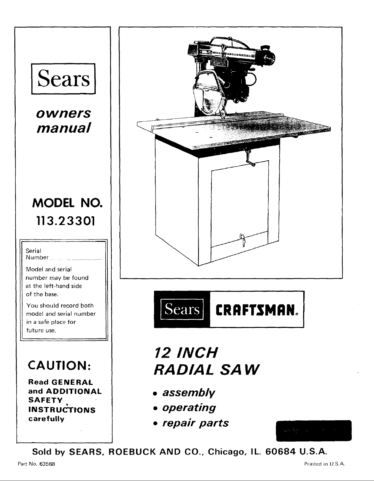
Craftsman 11323301 Owner’s Manual
]Sears]
owners
manual
MODEL NO.
113.23301
Serial
Number ....
Model and serial
number may be found
at the left-hand side
of the base.
You should record both
model and serial number
in a safe place for
future use.
CAUTION:
Read GENERAL
and ADDITIONAL
SAFETY-
INSTRUCTIONS
carefully
b:
[RRFTSMRNo
12 INCH
RADIAL SAW
• assembly
• operating
• repair parts
Sold by SEARS, ROEBUCK AND CO., Chicago, IL. 60684 U.S.A.
Part No. 63568 Printed ill U.S.A.
FULL ONE YEAR WARRANTY ON CRAFTSMAN RADIAL SAWS
If within one year from the date of purchase, this Craftsman Radial Saw fails due to a defect in material or
workmanship, Sears will repair it, free of charge.
Warranty service is available by simply contacting the nearest Sears store or Service Center throughout the
United States.
This warranty gives you specific legal rights, and you may also have other rights which vary from state to
• state.
SEARS, ROEBUCK AND CO.
BSC 41-3
SEARS TOWER
CHICAGO, IL 60684
general safety instructions for power tools
1. KNOW YOUR POWER TOOL 13.
Read the owner's manual carefully, Learn its
application and limitations as well as the specific
potential hazards peculiar to this tool.
2. GROUND ALL TOOLS 14.
This tool is equipped with an approved 3-conductor
cord and a 3prong grounding type plug to fit the
proper grounding type receptacle. The green conductor 15.
in the cord is the grounding wire. Never connect the
green wire to a live terminal,
3. KEEP GUARDS IN PLACE
in working order, and in proper adjustment and
alignment.
4. REMOVE ADJUSTING KEYS
AND WRENCHES
Form habit of checking to see that keys and adjusting
wrenches are removed from tool before turning it on.
5. KEEP WORK AREA CLEAN
Cluttered areas and benches irrvite accidents. Floor
must not be slippery due to wax or sawdust,
6. AVOID DANGEROUS ENVIRONMENT
Don't use power tools in damp or wet locations or
expose them to rain, Keep work area well lighted.
Provide adequate surrounding work space. 19.
7. KEEP CHILDREN AWAY
Al! visitors should be kept a safe distance from work
area.
8. MAKE WORKSHOP KID-PROOF
- with padlocks, master switches, or by removing
starter keys, 20.
9. DON'T FORCE TOOL
It will do the job better and safer at the rate for which
it was designed•
10. USE RIGHT TOOL
Don't force tool or attachment to do a iob it was not
designed for
11. WEAR PROPER APPAREL
Do not wear loose clothing, gloves, neckties or jewelry
(rings, wrist watches) to get caught in moving parts.
Nonslip footwear is recommended. Wear protective 21.
hair covering to contain long hair. Roll long sleeves
above the el bow.
12. USE SAFETY GOGGLES (Head Protection)
Wear Safety goggles (must comply with ANS Z87.1) at
all times. Also, use face or dust mask if cutting
operation is dusty, and ear protectors (plugs or muffs)
during extended periods of operation.
SECURE WORK
Use clamps or a vise to hold work when practical. It's
safer than using your hand, frees both hands to operate
tool.
DON'T OVERREACH
Keep proper footing and balance at all times.
MAINTAIN TOOLS WITH CARE
Keep tools sharp and clean for best and safest
performarrce. Follow instructions for lubricating and
changing accessories.
16. DISCONNECT TOOLS
before servicing; when changing accessories such as
blades, bits, cutters, etc.
17, AVOID ACCIDENTAL STARTING
Make sure switch is in "OFF" position before plugging
in.
18. USE RECOMMENDED ACCESSORIES
Consult the owner's manual for recommended
accessories. Follow the instructions that accompany
the accessories. The use of improper accessories may
cause hazards.
NEVER STAND ON TOOL
Serious injury could occur if the tool is tipped or if the
cutting tool is accidentally contacted.
Do not store materials above or near the tool such that
it is necessary to stand on the toot to reach them.
CHECK DAMAGED PARTS
Before further use of the tool, a guard or other part that
is damaged should be carefully checked to ensure that it
will operate properly and perform its ntended function.
Check for alignment of moving parts, binding of mowng
parts, breakage of parts, mounting, and any other
conditions that may .affect its operation. A guard or
other part that is damaged should be properly repaired
or replaced
DIRECTION OF FEED
Feed work into a blade or cutter against the direction
of rotation of the blade or cutter only.
22.
NEVER LEAVE TOOL RUNNING
UNATTENDED
Turn power off. Don't leave tool until it cornes to a
complete stop.
additional safety instructions for radial saws
CAUTION: Always disconnect the power cord before
removing the guard, changing the cutting tool, changing the
set-up or making adjustments. Shut off motor before
performing layout work on the saw table.
WARNING: DO NOT CONNECT POWER CORD UNTIL
THE FOLLOWING STEPS HAVE BEEN
SATISFACTORILY COMPLETED:
I. Assembly and alignment.
II. Examination and operating familiarity with ON-OFF
switch, elevation control, yoke index and lock, bevel
index and lock, carriage lock, guard clamp screw,
spreader and antikickbaek device, and miter index and
lock.
III. Review and understanding of all Safety Instructions and
Operathrg Procedures thru-out manual.
INSTALLATION
1. Bet carnage lock before moving the saw.
2. Bolt the saw to the floor if it tends to slip, walk, or
slide during normal operation.
3. Mount the saw so the table
- is approximatety 39" above the floor;
-- slopes slightly downward to the rear so the carriage
wil! not roll forward due to gravity.
MINIMIZE ACCIDENT POTENTIAL
Most accidents are caused by FAILURE TO FOLLOW
setup and operating instructions:
(A) GENERAL
--Avoid awkward hand positions, where a sudden stip
could cause a hand to move into a sawblade or other
cutting tool. Never reach in back of or around the
cutting tool with either hand to hold down the
workpiece, or for any other reason; DO NOT place
fingers or hands in the path of the sawblade.
- Neve_ saw, dado, mold, or rabbet unless the proper
guard is installed and set up as instructed.
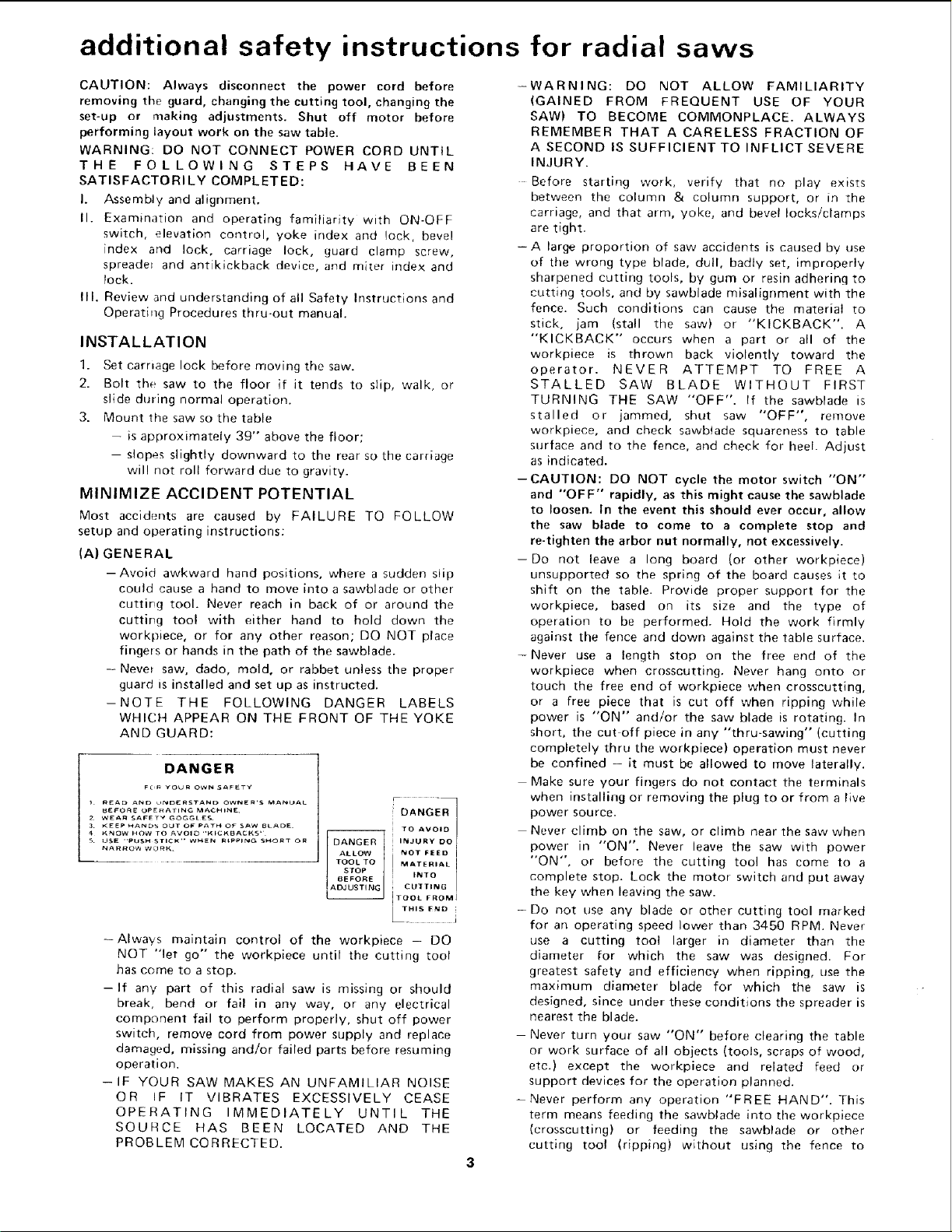
-NOTE THE FOLLOWING DANGER LABELS
WHICH APPEAR ON THE FRONT OF THE YOKE
AND GUARD:
DANGER
TO AVOID
INJURY DO
NOT FEED
MATERIAL
INTO
CU]TING
TOOL FROMJ
--Always maintain control of the workp_ece - DO
NOT "let go" the workpiece until the cutting tool
has come to a stop.
-If any part of this radial saw is missing or should
break, bend or fall in any way, or any electrical
component fail to perform properly, shut off power
switch, remove cord from power supply and replace
damaged, missing and/or failed parts before resuming
operation.
- IF YOUR SAW MAKES AN UNFAMILIAR NOISE
OR IF IT VIBRATES EXCESSIVELY CEASE
OPERATING IMMEDIATELY UNTIL THE
SOURCE HAS BEEN LOCATED AND THE
PROBLEM CORRECTED.
-WARNING: DO NOT ALLOW FAMILIARITY
(GAINED FROM FREQUENT USE OF YOUR
SAW) TO BECOME COMMONPLACE. ALWAYS
REMEMBER THAT A CARELESS FRACTION OF
A SECOND IS SUFFICIENT TO INFLICT SEVERE
INJURY.
Before starting work, verify that no play exists
between the column & column support, or in the
carriage, and that arm, yoke, and bevel locks/clamps
are tight.
= A large proportion of saw accidents is caused by use
of the wrong type blade, dull, badly set, improperly
sharpened cutting tools, by gum or resin adhering to
cutting tools, and by sawblade misalignment with the
fence. Such conditions can cause the material to
stick, jam (stall the saw) or "KICKBACK". A
"KICKBACK" occurs when a part or all of the
workpiece is thrown back violently toward the
operator. NEVER ATTEMPT TO FREE A
STALLED SAW BLADE WITHOUT FIRST
TURNING THE SAW "OFF". If the sawblade is
stalled or jammed, shut saw "OFF", remove
workpiece, and check sawbtade squareness to table
surface and to the fence, and check for heel. Adjust
as indicated.
--CAUTION: DO NOT cycle the motor switch "ON"
and "OFF" rapidly, as this might cause the sawblade
to loosen. In the event this should ever occur, allow
the saw blade to come to a complete stop and
re-tighten the arbor nut normally, not excessively.
--Do not leave a long board (or other workpieee)
unsupported so the spring of the board causes it to
shift on the table. Provide proper support for the
workpiece, based on its size and the type of
operation to be performed. Hold the work firmly
against the fence and down against the table surface.
-Never use a length stop on the free end of the
workpiece when crosscutting, Never hang onto or
touch the free end of workpiece when crosscutting,
or a free piece that is cut off when ripping while
power is "ON" and/or the saw blade is rotating. In
short, the cut off piece in any "thru-sawing" (cutting
completely thru the workpiece) operation must never
be confined - it must be allowed to move laterally.
Make sure your fingers do not contact the terminals
when installing or removing the plug to or from a live
power source.
Never climb on the saw, or climb near the saw when
power in "ON". Never leave the saw with power
"ON", or before the cutting tool has come to a
complete stop. Lock the rnotor switch and put away
the key when leaving the saw.
-Do not use any blade or other cutting tool marked
for an operating speed lower than 3450 RPM. Never
use a cutting toot larger in diameter than the
diameter for which the saw was designed. For
greatest safety and efficiency when ripping, use the
maximum diameter blade for which the saw is
designed, since under these conditions the spreader is
nearest the blade.
- Never turn your saw "ON" before clearing the table
or work surface of all objects (tools, scraps of wood,
etc.} except the workpiece and related feed or
support devices for the operation planned.
-Never perform any operation "FREE HAND". This
term means feeding the sawblade into the workpiece
(crosscutting) or feeding the sawblade or other
cutting tool (ripping) without using the fence to
additional safety instructions for radial saws
support _)_ guide the workpJece, to prevent rotating
or twisting of the workpieee during the operation.
Never "RIP'" in the crosscut position. Never make a
miter cut with the arm in the 90 ° crosscut position.
- Never lower a revolving cutting tool into the table or
a workpiece without first locking the Carriage Lock
Knob. Release the knob only after grasping the Yoke
Handle. Otherwise the cutting tool may grab the
workpiece and be propelled toward you.
-The sawblade, dado, or other cutting tool must be
removed from the saw arbor before using the
accessory shaft (rear end of the saw motor). NEVER
operate the saw with cutting tools (including sanding
accessories) installed on both ends of the saw arbor.
(B) RIPPING
1. Feed force when ripping must always be applied
BETWEEN THE SAW BLADE AND THE FENCE.
. . use a "PUSH STICK" for narrow or short work.
2. Whenever possible, use the in-rip position this
provides minimum obstruction for feeding by hand
or push stick as appropriate.
3. Do nut release the workpiece before operation is
complete - push the workpiece all the way past the
rear (outfeed or exit) of the sawblade.
4, Make swe by trial before starting the cut that the
antikickback pawls will stop a kickback once it has
started, Points of pawls must be SHARP, Reptace
when potnts are dull or rounded.
5. Use a push stick when ripping short (under 12
inches) or narrow (under 6 inches wide) wot kpieces.
6. CAUTION: Never reposition the Guard or
antikickback with power "'ON".
7. A "KICKBACK" occurs during a rip-type
operation. It can occur when the workpiece closes
in on the rear (outfeed side) of the sawblade
(pinching), binds between the fence and the
sawblade. (heel), or is grabbed by the sawblade teeth
(wrong-way feed) at the uutfeed side. "PINCHING"
is genera!ly avoided by utilization of the spreader,
and a sharp sawblade of the corrective type for the
workpieee being cut. "HEEL" carl be avoided by
maintaining the sawblade exactly parallel to the
fence. (see "DANGER" warning on guard) it can
be avoided by maintaining parallelism of sawblade
to fence, feeding into the sawblade from the nose of
the guard only, and by utilizing the spreader.
8. Position the nose of the guard to just clear the
workpiece, and position!adjust the antikickback
and spreader devices as instructed.
9. NEVER cut more than one piece at a time by
stacking workpieces vertically.
10. NEVER feed a workpiece tbru the saw with another
piece (butting second piece against trailing edge of
piece being cut), even if of the same thickness. Feed
each workpiece individually thru the sawblade, and
completely beyond the sawblade, before ripping the
next wo_kpiece. Use push stick if the rip cut is Jess
than 6" wide.
11. DO NOT pull the workpiece thru the sawblade
position your body at the nose fin feed) side of
the guard: start and complete the cut from that
same side. This wilt require added table support
for long pieces.
12. Plastic and composition (like styrene and
hardboard) materials may be cut on your saw.
However, since these are usually quite hard arrd
(C) CROSSCUTTING
(D) ACCESSORI ES
slippery, the antikickback pawls may not stop a
kickback.
Therefore, rip with the firfished side down {next to
the table) and be especially attentive to following
proper set-up and cutting procedures. Do not stand,
or permit anyone else to stand, in line with a
potential kickback.
13. When sawing 1/4" or thinner materials, follow all
normal ripping procedures except set sawblade into
table top at least 1/8". ]-his will minimize the
tendency for the sawblade to climb upon top of the
workpiece, and possibly cause an accident. DO NOT
let go of or stop feeding the workpiece between the
blade and fence until you have pushed it completely
past the antikTckback pawls. Otherwise the
workpiece could get into the back of the sawblade
and be thrown violently [rom the saw in the
direction opposite to the feed direction. This is the
same action that would occur if the instructions of
the DANGER warning on the guard is aborted. Do
not stand, or permit anyone else to stand, in line
with the path of a workpiece that may be thrown
from the saw in this manner.
14. Position the saw so neither you, a helper, or a casual
observer is forced to stand in line with the
sawblade.
15. Use extra care when ripping wood that has a twisted
grain or is twisted or bowed - it may rock co the
table and/or pinch the sawblade. If bowed across
the width, place concave side down against the
table.
1. ALWAYS RETURN THE CARRIAGE TO THE
FULL REARWARD POSITION AT CONCLUSION
OF EACH CROSSCUT TYPE OPERATION. Never
remove your hand from the Yoke Handle unless the
carriage is in this position. Otherwise the cutting
tool may climb up on the workpiece and be
propelled toward you.
2. Place guard in horizontal position and adjust
antikickback pawls to just clear the top of the fence
or workpiece, whichever is higher.
3. NEVER gang crosscut lining up more than one
workpiece in front of the fence stacked vertically,
or horizontally outward on the table and then
pulling saw thru: the blade could pick up one or
more pieces and cause a binding or loss of control
and possible injury.
4. Do not position the Arm so the operation you are
performing permits the cutting tool to extend
beyond the edges of the Table.
1. Use only recommended accessories as listed in
accessory section of this manual.
2. Never operate this saw when equipped with a dado
head or molding head unless the molding head
guard is installed - see listing of recommended
accessories. The only exception is when "top side"
dadoing or molding, when the sawblade guard must
be used. See detailed instructions that accompany
the dado head, molding head, and molding head
guard.
3. The use of abrasive or cut-off wheels, or wire
wheels, can be dangerous and is not recommended.
(Abrasive or cut-off wheels are used to saw many
different materials including metals, stone, and
glass.)
ADDITIONAL SAFETY INSTRUCTIONS FOR RADIAL SAWS
WEAR YOUR
The operation of any power tool can result in foreign
objects being thrown into the eyes, which can result in
severe eye damage. Always wear safety goggles complying
with ANSI Z87.1 (shown on Package) before commencing
power tool operation. Safety Goggles are available at Sears
retail or catalog stores.
CONTENTS
Page
Operating Controls ............................ 15
Basic Saw Operations ........................... 18
Trouble Shooting .............................. 21
Motor Trouble Shooting Chart ................ 25-26
Repair Parts .................................. 28
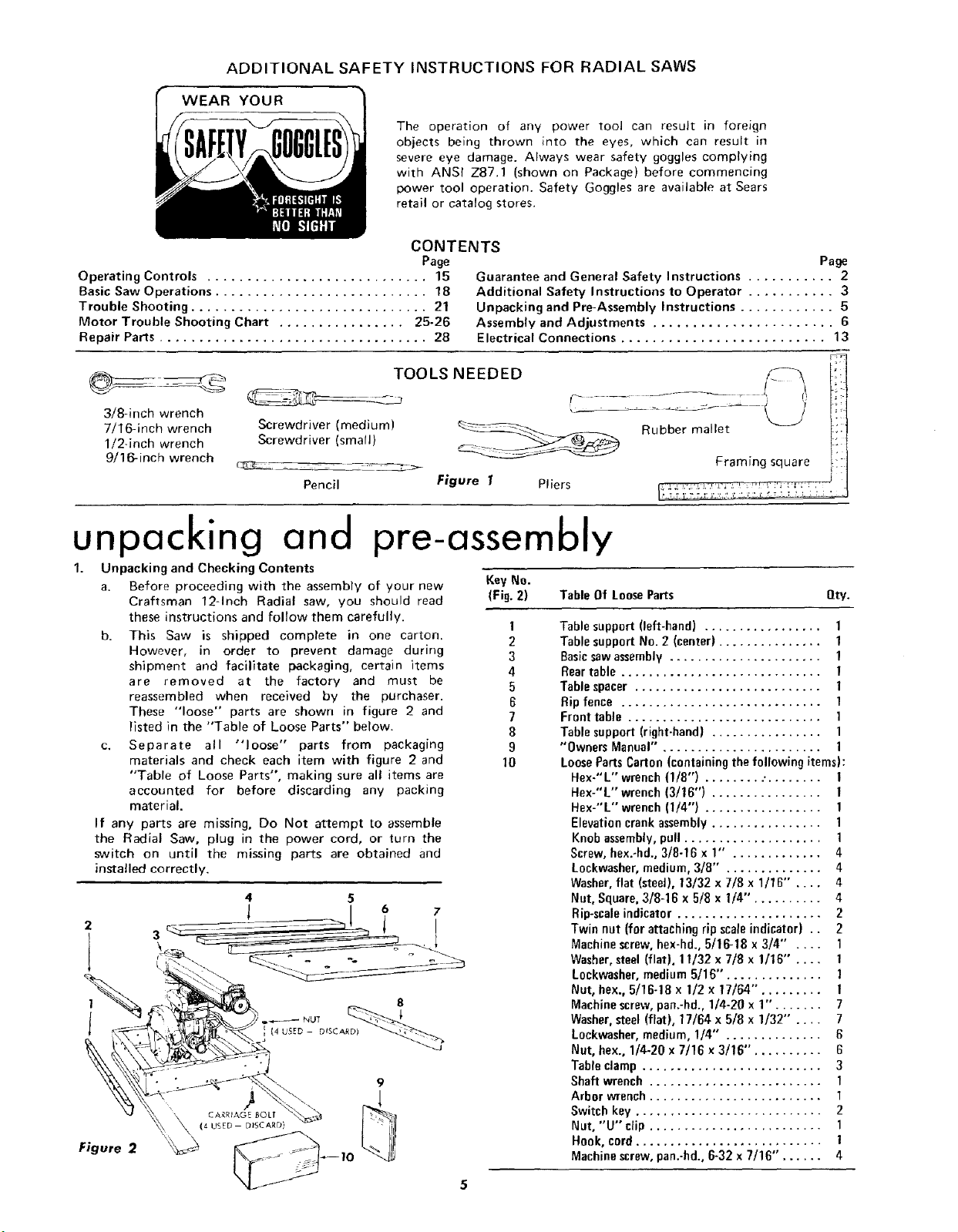
TOOLS NEEDED /:_ li
3/8-inch wrench
7/16-inch wrench
1!2-inch wrench
9/16-inch wrench
S rewOrlver(smo,,) I::
_._ _ Framing square i "
Pencil Figure f Pliers _: ,: !
Page
Guarantee and General Safety Instructions ........... 2
Additional Safety Instructions to Operator ........... 3
Unpacking and Pre-Assembly Instructions ............ 5
Assembly and Adjustments ....................... 6
Electrical Connections .......................... 13
F-'
unpacking and pre-assembly
1. Unpacking and Checking Contents
a. Before proceeding with the assembly of your new
Craftsman 12-Inch Radial saw, you should read
these instructions and follow them carefully.
b. This Saw is shipped complete in one carton.
However, in order to prevent damage during
shipment and facilitate packaging, certain items
are removed at the factory and must be
reassembled when received by the purchaser.
These "loose" parts are shown in figure 2 and
listed in the "Table of Loose Parts" below.
c, Separate all "loose" parts from packaging
materials and check each item with figure 2 and
"Table of Loose Parts", making sure all items are
accounted for before discarding any packing
material.
If any parts are missing, Do Not attempt to assemble
the Radial Saw, plug in the power cord, or turn the
switch on until the missing parts are obtained and
installed correctly.
4 5
2
8
Figure 2
Key No.
(Fig. 2) Table Of Loose Parts Qty.
I
2
3
4
5
6
7
8
9
10
Tablesupport (left-hand) ................. 1
Tablesupport No. 2 (center) ............... 1
Basicsawassembly...................... 1
Reartable ............................. 1
Tablespacer ........................... 1
Ripfence ............................. 1
Fronttable ............................ 1
Tablesupport(right-hand) ................ 1
"Owners Manual" . ...................... 1
LoosePartsCarton (containingthefollowing items):
Hex-"L" wrench(1/8") ......... •........ 1
Hex-"L" wrench(3/16") ................ 1
Hex-"L" wrench(1/4") ................. 1
Elevationcrankassembly................ 1
Knobassembly,pull .................... 1
Screw,hex.-hd., 3/8-16 x 1" . ............ 4
Lockwasher, medium,3/8" . ............. 4
Washer,flat (steel), 13/32 x 7/8 x 1/16" .... 4
Nut, Square,3/8-16 x 5/8 x 1/4". ......... 4
Rip-scaleindicator..................... 2
Twin nut (for attaching rip scaleindicator) .. 2
Machinescrew,hex-hd.,5/16-18 x 3/4" .... 1
Washer,steel(flat), 11/32 x 7/8 x 1/16" .... 1
Lockwasher,medium5/16"'. ............. 1
Nut, bex., 5/16-18 x 1/2 x 17/64". ........ 1
Machinescrew,pan.-hd.,1/4-20 x 1". ...... 7
Washer.steel(flat), 17/64 x 5/8 x 1/32" .... 7
Lockwasher,medium,1/4" . ............. 6
Nut, hex., 1/4-20 x 7/16 x3/16". ......... 6
Tableclamp .......................... 3
Shaft wrench ......................... 1
Arbor wrench......................... 1
Switch key ........................... 2
Nut, "'U'"clip ......................... 1
Hook,cord........................... !
Machinescrew,pan.-hd.,6-32 x 7/16". ..... 4
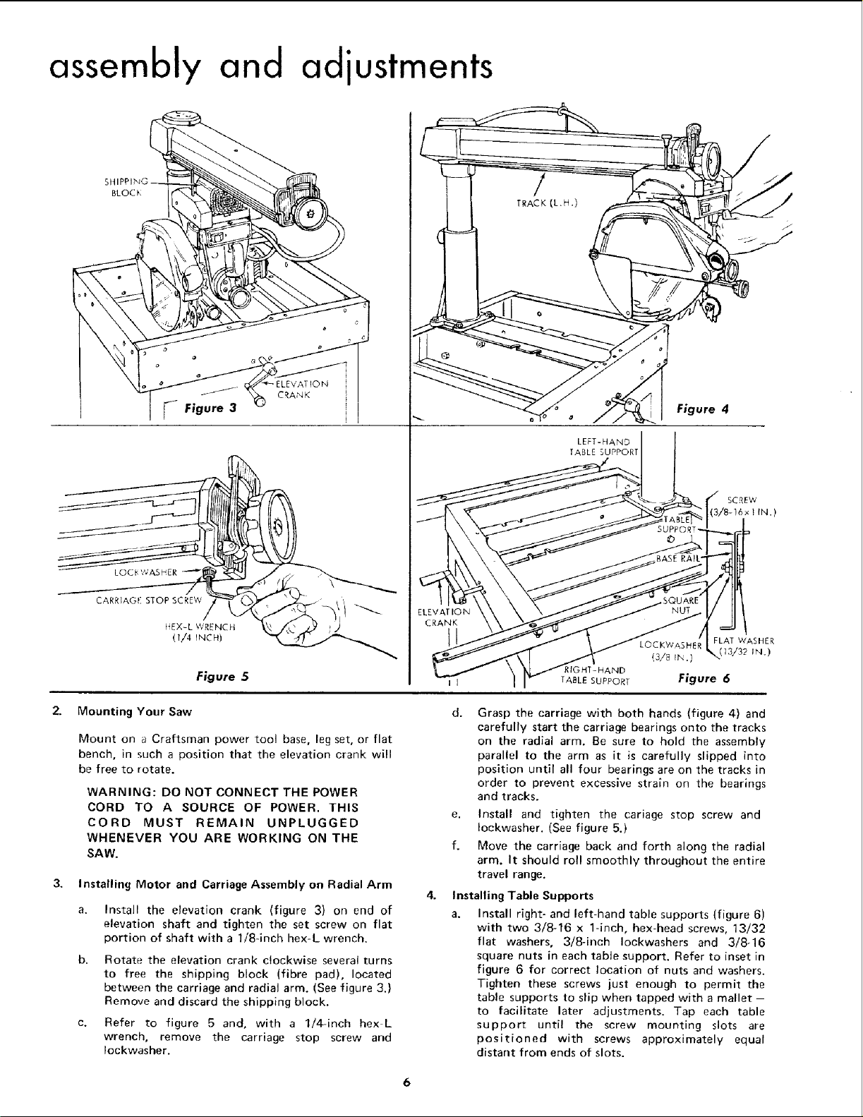
assembly and adjustments
BLOCK
LEFT-HAND
TABLE SUPPORT
Figure 4
CARRIAGE STOP SCREW
14EX-L WRENCH _ .)
0/4 rNCH)
Figure 5
2.. Mounting Your Saw
Mount on a CrafLsman power tool base, leg set, or flat
bench, in such a position that the elevation crank will
be free to rotate.
WARNING: DO NOT CONNECT THE POWER
CORD TO A SOURCE OF POWER, THIS
CORD MUST REMAIN UNPLUGGED
WHENEVER YOU ARE WORKING ON THE
SAW.
3, Installing Motor and Carriage Assembly on Radial Arm
Install the elevation crank (figure 3} on end of
elevation shaft and tighten the set screw on flat
portion of shaft with a 1/8-inch hex-L wrench.
Rotate the elevation crank clockwise several turns
to free the shipping block (fibre pad), located
between the carriage and radial arm. (See figure 3.)
Remove and discard the shipping block.
Refer to figure 5 and, with a 1/4-inch hex L
wrench, remove the carriage stop screw and
Iockwasher.
SCREW
3/8-16 x I IN.)
LOCKWASHER FLAT WASHER
(3/8 In .)
I [ TABLE SUPPORf
d. Grasp the carriage with both hands (figure 4) and
carefully start the carriage bearings onto the tracks
on the radial arm, Be sure to hold the assembly
parallel to the arm as it is carefully slipped into
position until all four bearings are on the tracks in
order to prevent excessive strain on the bearings
and tracks.
e, Install and tighten the cariage stop screw and
Iockwasher. (See figure 5.)
f. Move the carriage back and forth along the radial
arm. It should roll smoothly throughout the entire
travel range.
Installing Table Supports
a. Install right- and left-hand table supports (figure 6)
with two 3/8-16 x 1-inch, hex-head screws, 13/32
flat washers, 3/8-inch Iockwashers and 3/8-16
square nuts in each table support. Refer to inset in
figure 6 for correct location of nuts and washers.
Tighten these screws just enough to permit the
table supports to slip when tapped with a mallet -
to facilitate later adjustments. Tap each table
support until the screw mounting slots are
positioned with screws approximately equal
distant from ends of slots.
(13/32 IN.)
Figure 6
6
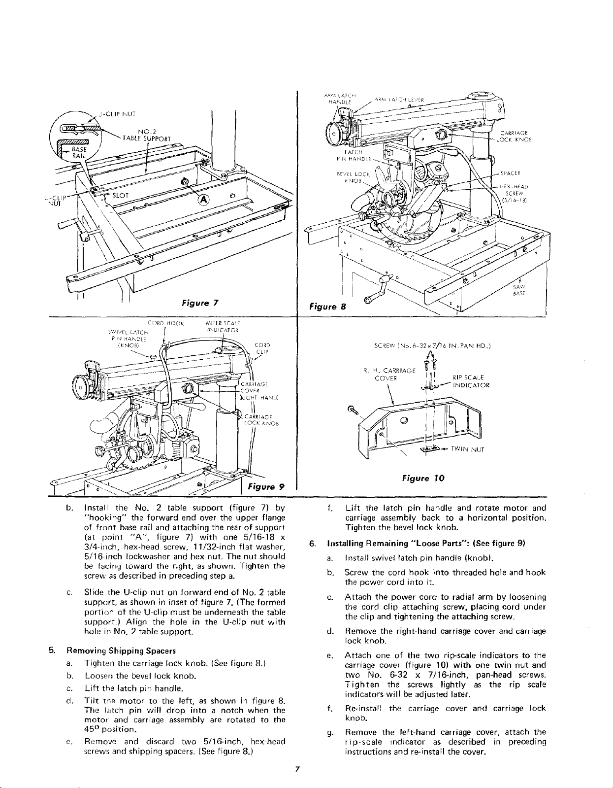
NUT
NO.2
SUPPORT
LATCH
PiN HAPJ
BEVEL LOCK
CARRIAGE
LOCK KNOB
Figure 7
MrTER SCALE
INDICATOR
Install the No. 2 table support (figure 7) by
"hooking" the forward end over the upper flange
of front base rail and attaching the rear of support
(at point "'A', figure 7) with one 5/16-18 x
3/4-inch, hex-head screw, 11/32-inch flat washer,
5/16-inch Iockwasher and hex nut. The nut should
be facing toward the right, as shown. Tighten the
screw as described in preceding step a.
Slide the U-clip nut on forward end of No. 2 table
support, as shown in inset of figure 7. (The formed
portion of the U-clip must be underneath the table
support.) Align the hole in the U-clip nut with
hole in No. 2 table support,
5.
Removing Shipping Spacers
a. Tighten the carriage lock knob. (See figure 8.)
b. Loosen the bevel lock knob.
c. Lift the latch pin handle.
d. Tilt the motor to the left, as shown in figure 8.
The latch pin will drop into a notch when the
motor and carriage assembly are rotated to the
45 ° position.
e. Remove and discard two 5/16-inch, hex-head
screws and shipping spacers, (See figure 8.)
CORD
CLIP
Figure 9
I
Figure 8
SCREW (No.6 32×7/i6 IN.PAN HD.)
A
R H CARRIAGE '_
' dOVER I _1 RIPSCAL_
\ @_"_ IN DIC AT OR
Figure I0
f. Lift the latch pin handle and rotate motor and
carriage assembly back to a horizontal position.
Tighten the bevel lock knob.
Installing Remaining "Loose Parts": (See figure 9)
a. Install swivel latch pin handle (knob).
b. Screw the cord hook into threaded bole and hook
the power cord into it.
c. Attach the power cord to radial arm by loosening
the cord clip attaching screw, placing cord under
the clip and tightening the attaching screw.
d. Remove the right-hand carriage cover and carriage
lock knob.
e. Attach one of the two rip-scale indicators to the
carriage cover (figure 10) with one twin nut and
two No. 6-32 x 7/16-inch, pan-head screws.
Tighten the screws lightly as the rip scale
indicators will be adjusted later.
f. Re-install the carriage cover and carriage lock
knob.
g. Remove the left-hand carriage cover, attach the
rip-scale indicator as described in preceding
instructions and re-install the cover.
bASE
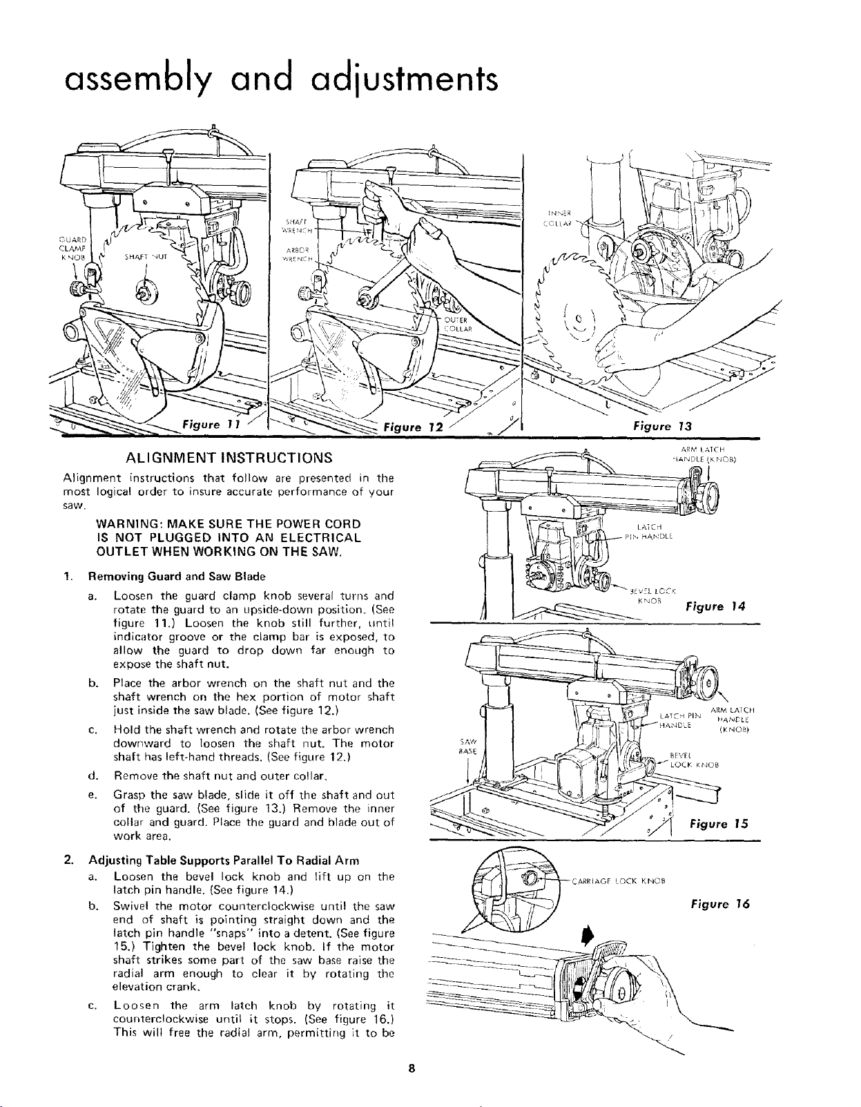
assembly and adiustments
Figure 11
ALIGNMENT INSTRUCTIONS
Alignment instructions that follow are presented in the
most logical order to insure accurate performance of your
saw.
WARNING: MAKE SURE THE POWER CORD
IS NOT PLUGGED INTO AN ELECTRICAL
OUTLET WHEN WORKING ON THE SAW.
Removing Guard and Saw Blade
a. Loosen the guard clamp knob several turns and
rotate the guard to an upside-down position. (See
figure 11.) Loosen the knob still further, until
indicator groove or the clamp bar is exposed, to
allow the guard to drop down far enough to
expose the shaft nut.
b. Place the arbor wrench on the shaft nut and the
shaft wrench on the hex portion of motor shaft
just inside the saw blade. (See figure 12.)
c. Hold the shaft wrench and rotate the arbor wrench
dowr_ward to loosen the shaft nut. The motor
shaft has left-hand threads. (See figure 12.)
d. Remove the shaft nut and outer collar,
e.
Grasp the saw blade, slide it off the shaft and out
of the guard. {See figure 13.) Remove the inner
collar and guard. Place the guard and blade out of
work area.
SAW
BASE
Figure 13
K_OB Figure 14
_L
Figure 15
Adjusting Table Supports Parallel To Radial Arm
a. Loosen the bevel lock knob and lift up on the
latch pin handle. (See figure 14.)
b. Swivel the motor counterclockwise until the saw
end of shaft is pointing straight down and the
latch pin handle "snaps" into a detent. (See figure
15.) Tighten the bevel lock knob. If the motor
shaft strikes some part of the saw base raise the
radial arm enough to clear it by rotating the
elevation crank.
c. Loosen the arm latch knob by rotating it
counterclockwise until it stops. (See figure 16.)
This wilt free the radial arm, permitting it to be
Figure 16
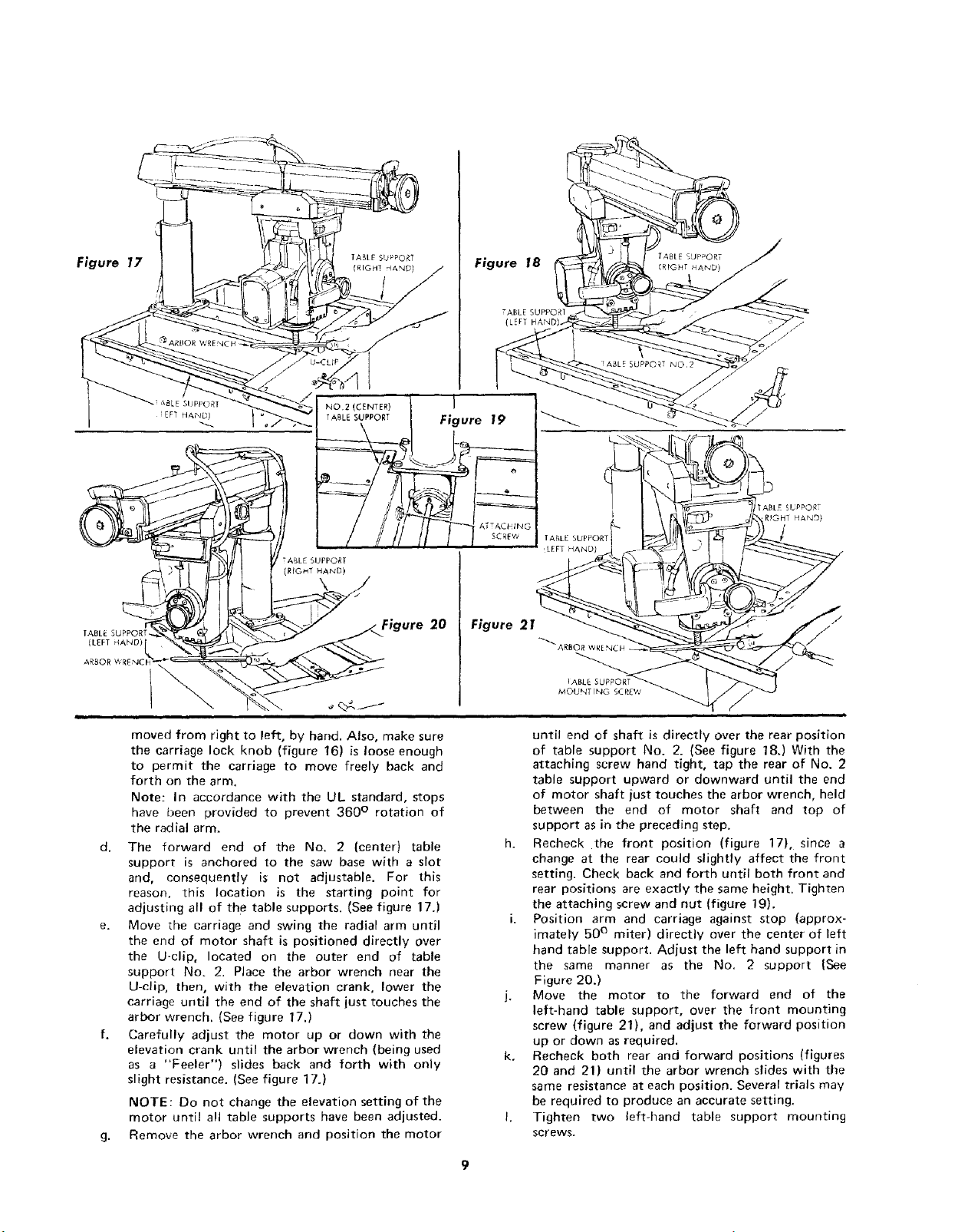
Figure 18
I
Figure 21
(LEFT
ABLE SUPPORT
MOUNT [NG 5C
2
moved from right to left, by hand, Also, make sure
the carriage lock knob (figure 16) is loose enough
to permit the carriage to move freely back and
forth on the arm.
Note: In accordance with the UL standard, stops
have been provided to prevent 360 ° rotation of
the radial arm,
d. The forward end of the No. 2 (center) table
support is anchored to the saw base with a slot
and, consequently is not adjustable. For this
reason, this location is the starting point for
adjusting all of the table supports. (See figure 17.)
e. Move the carriage and swing the radial arm until
the end of motor shaft is positioned directly over
the U-clip, located on the outer end of table
support No. 2. Place the arbor wrench near the
U-clip, then, with the elevation crank, lower the
carriage until the end of the shaft just touches the
arbor wrench. (See figure 17.)
f. Carefully adjust the motor up or down with the
elevation crank until the arbor wrench (being used
as a "Feeler") slides back and forth with only
slight resistance. (See figure 17.)
NOTE: Do not change the elevation setting of the
motor until all table supports have been adjusted.
g. Remove the arbor wrench and position the motor
until end of shaft is directly over the rear position
of table support No. 2. (See figure 18.) With the
attaching screw hand tight, tap the rear of No. 2
table support upward or downward until the end
of motor shaft just touches the arbor wrench, held
between the end of motor shaft and top of
support as in the preceding step.
h. Recheck the front position (figure 17), since a
change at the rear could slightly affect the front
setting. Check back and forth until both front and
rear positions are exactly the same height. Tighten
the attaching screw and nut (figure 19).
i. Position arm and carriage against stop (approx-
imately 50 ° miter) directly over the center of left
hand table support. Adjust the left hand support in
the same manner as the No. 2 support {See
Figure 20.)
j. Move the motor to the forward end of the
left-hand table support, over the front mounting
screw (figure 21), and adjust the forward position
up or down as required.
k. Recheck both rear and forward positions (figures
20 and 21) until the arbor wrench slides with the
same resistance at each position. Several trials may
be required to produce an accurate setting.
I. Tighten two left-hand table support mounting
screws.
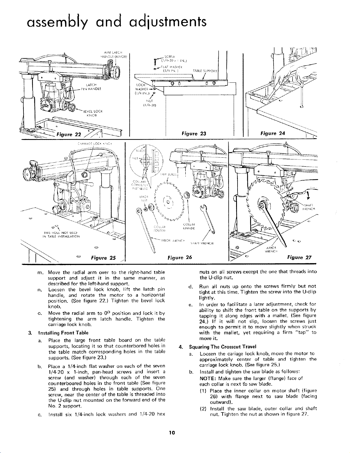
assembly and adjustments
ARM LAICH
HANDLE (K NOB)
_,_ FLAT ,_/ASH ER
(1/4 IN. ) TABLE SLJPPORI
LATCH
"4 HANDLE
BEVEL LOCK
KNOB
(1/4 iN.)
WASHE R.?'_
NUT
l I/4- 2O)
Figure 22
IFI[S HOLE NOT USED
IN TABLE _NSTALLAItON
Figure 25
m. Move the radial arm over to the right-hand table
support and adjust it in the same manner, as
described for the left-hand support.
n. Loosen the bevel lock knob, lift the latch pin
handle, and rotate the motor to a horizontal
position. (See figure 22.) Tighten the bevel lock
knob.
o. Move the radial arm to 0° position and lock it by
tightening the arm latch handle. Tighten the
carriage lock knob.
Installing Front Table
a. Place the large front table board on the table
supports, locating it so that eounterbored holes in
the table match corresponding holes in the table
supports. (See figure 23.)
b. Place a 1/4-inch flat washer on each of the seven
1/4-20 x 1-inch, pan-head screws and insert a
screw (and washer) through each of the seven
eounterboared holes in the front table (See figure
25) and through holes in table supports. One
screw, near the center of the table is threaded into
the U-clip nut mounted on the forward end of the
No, 2 support.
c. Install six 1/4-inch lock washers and 1/4-20 hex
Figure 23 Figure 24
'€,'RENC h
Figure 27
nuts on all screws except the one that threads into
the U-clip nut.
d. Run all nuts up onto the screws firmly but not
tight at this time. Tighten the screw into the U-clip
lightly.
In order to facilitate a later adjustment, check for
ability to shift the front table on the supports by
tapping it along edges with a mallet. (See figure
24.) If it will not slip, loosen the screws just
enough to permit it to move slightly when struck
with the mallet, yet requiring a firm "tap" to
move it.
4.
Squaring The Crosscut Travel
a. Loosen the cariage lock knob, move the motor to
approximately center of table and tighten the
carriage lock knob. (See figure 25.)
b. Install and tighten the saw blade as follows:
NOTE: Make sure the larger (flange) face of
each collar is next tb saw blade.
(1) Place the inner collar on motor shaft (figure
26) with flange next to saw blade (facing
outward).
(2) Install the saw blade, outer collar and shaft
nut. Tighten the nut as shown in figure 27.
10
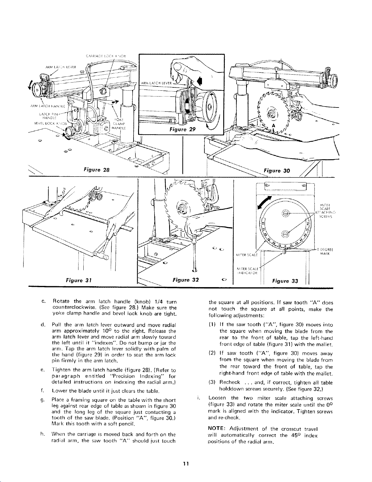
2_RM [&ECH klAN tt_
LATCH
HANDLE
BEvEl lOCK _rdO_
Figure 28
Figure 3 !
C.
Rotate the arm latch handle (knob) 1/4 turn
counterclockwise. (See figure 28.) Make sure the
yoke clamp handle and bevel lock knob are tight.
d.
Pull the arm latch lever outward and move radial
arm approximately 10 ° to the right. Release the
arm latch lever and move radial arm slowly toward
the left until it "indexes". Do not bump or jar the
arm. Tap the arm latch lever solidly with palm of
the hand (figure 29) in order to seat the arm lock
pin firmly in the arm latch.
e. Tighten the arm latch handle (figure 28). (Refer to
paragraph entitled "Precision Indexing" for
detailed instructions on indexing the radial arm.)
f. Lower the blade until it just clears the table.
g. Place a framing square on the table with the short
leg against rear edge of table as shown in figure 30
and the long leg of the square just contacting a
tooth of the saw blade. (Position "A", figure 30.)
Mark this tooth with a soft pencil.
When the carriage is moved back and forth on the
radial arm, the saw tooth "A" should just touch
Figure 32
Figure 30
MJTER
SCA[E
ZHNG
SCREWS
Figure 33
the square at all positions. If saw tooth "A" does
not touch the square at all points, make the
following adjustments:
(1) If the saw tooth ("A", figure 30) moves into
the square when moving the blade from the
rear to the front of table, tap the left-hand
front edge of table (figure 31) with the mallet.
(2) If saw tooth ("A", figure 30) moves away
from the square when moving the blade from
the rear toward the front of table, tap the
right-hand front edge of table with the mallet.
(3) Recheck ... and, if correct, tighten all table
holddown screws securely. (See figure 32.)
Loosen the two miter scale attaching screws
(figure 33) and rotate the miter scale until the 0°
mark is aligned with the indicator. Tighten screws
and re-check.
NOTE: Adjustment of the crosscut travel
will automatically correct the 45 ° index
positions of the radial arm.
11
 Loading...