

Craftsman 113232210 Owner’s Manual
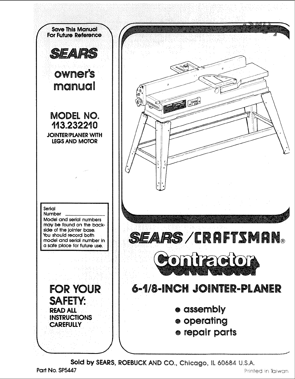
MODEL NO.
113.232210
JOINTER/PLANERWITH
LEGSAND MOTOR
Serial
Number
Model and serial numbers
may be found on the back-
side of the jointer base.
You should record both
model and serial number in
a safe place for future use::
tHl' ' 't
i
FORYOUR
6-!!E-INCH JOmHTER'PL ER
SAFETY:
READALL
INSTRUCTIONS
CAREFULLY
Sold by SEARS, ROEBUCK AND CO., Chicago, iL 6068,4 U.S.A_
Part No. SP5447 ?r_ ir_ r._,,_c_r_
• assembly
e operating
e repair parts
"L""Luu'u . -- ,,__'_

NTER/PLANER
of charge.
CONTACTING THE NEAREST SEARS SER-_
while this product is used in the United States.
rights, and you may also have other rights which
due to a
ROEBUCK AND CO. Dept: 698/731A. Sears Tower, Chicago, IL 60684
;:;IGENERAL SAFETY iNSTRUCTiONS FOR POWER TOOLS
KNOW;YOUR POWER TOOL
Read and understand the owner_ manual and
labels affixed to the tool. Learn its application and
limitationsas well as the specific potential hazards
peculiar to this tool.
2; GROUNDALL TOOLS
_ . This tool is equipped with an approved 3-conductor during extended periods of operation.
_ ::i:_cordanda 3-pr0nggr0unding type :plugto fitthe 13, SECURE WORK
proper grounding receptacle. The green con- Use clamps or avise tO hold work when practical.
ductor _inthe cord: is:the: grounding wire, Never It frees both hands to operate tooll
" i _connect the green wire to a live terminal. 14, DON'T OVERREACH
_3; KEEPGUARDS INPLACE " Keep proper footing and balance at all times.
i : i_i _ln wo[kingl order, and in: proPer adjustment and 15. MAINTAIN TOOLS WITH CARE
!. alignment; Keep tools sharp and clean for best and safest
12, USE SAFETYGOGGLES [HEAD PROTECTION)
Wear safety goggles (must comply with ANSI
Z87.1 ) at all times. Everyday eyeglassess are not
safety glasses. They only have impact resistant
lenses. Also, use face or dust mask ifcutting oper-
ation is dusty, and ear protectors (plugs or muffs)
:performance. Followinstructionsfor lubricatingand
J
I::'_ _. _:i! ::_:;:::_i_::_i:::::_:';i;: NEVERSTAND ON TOOL OR ITS STAND ;i _i::._ ::!
........... SH0_ ICHIL_ROOF _ Sed0us!njU_could occur if the toot is tipped or ff
i i_maste_switchesilby removing star-_ CUtting:tool is accidentally contacted: Do not' ....
;_:':' 5ring tools where: children Can_ get:: ::::_:,::store, materials above or near the tool such that it
;_'_.... ;_'_::_ ::_i;_:i_ is;tieCessaryto standon the to01 or its;stand to
::i_I:_ : :reachthern_ ::; ...... : :
job better and safer at the rate for _2o;: CHECK DAMAGED PARTS
1: itwas designed:: :i : : _: ::: Before furtheruse of the tool, aguard or other part
:: ::i thatJs damagedshouid be carefully checked to
:_::_i:::;:::::i::i_;Don;t for_i:io01s 0_ _achment to do a job it was :_:_: ensure::that it:wi!l operate properly and perform its
i_:::: intended Tunction:Check for alignment ol" moving
_::: ::::_::i_::: .... .... _ :_.... ' ...... : parts, bfndlngor mowng parts, breakage of parts,
"_ __"....... "':......... ' _" : : .............. ....................mountin ..... .... "
_;::::_ :::_:;_!;::D6_ ov_ :_nec_ies _:or:: :: ::: g; ana any other conditions that may anect
_:: :';:_i_:i;;:r_,_': _ri_+:_ _nt*.t _.nht_inrnov . : : =tsoperat;on. Aguardor other part that =sdamaged
_:' _ ......... ................................: ......_ ......_ n d : • should be properly repaired or rep aced
;::: =_:';:R_i _ge .............:el_w: ..........; .....' ............... Turn power off Don't leave toot untl it comes to a
e de ;: _::: ::: .........: ....
::: 21;: NEVERLEAVETOOLRUNNING UNATTENDED
complete stop.

..... n.........f....."n...........".....
add=tBoal sa sty structaons for jointer-planer
Safety is!a combination ofcommon sense, staying alert
and knowing flow your jointer-pianer works_.....
BEFORE USING THE JOINTER-PLANER:
WARNING: TO AVOID MISTAKES THAT COULD
CAUSE SERIOUS, PERMANENT INJURY, DO NOT
PLUG THE JOINTER-PLANER IN UNTIL THE FOL-
LOWING STEPS HAVE BEEN SATISFACTORILY
COMPLETED.
1. Assembly and alignment.
2. Learn the function and proper use of the on-off
switch, fence slide locking handle, cutter guard,
depth of cut hand wheel, locks and stops, fence
bevel lock handle, ouffeed table, infeed table and
hold-down/push-blocks.
3. Read and understand all safety instructions and
operating procedures throughout the manual.
4. Read the following labels which appear on the
jointer-planer:
BEFORE EACH USE:
1. Inspect your jointer-pfaner.
WARNING: THE 2-INCH JOINTER-PLANER PULLEY
AND THE 2-1/2 INCH MOTOR PULLEY FURNISHED
WILL RUNTHE CUTTER HEAD AT ABOUT 4300 RPM
WHEN USED WITH A 3450 RPM MOTOR. USE OF
DIFFERENT TYPES OF PULLEYS OR MOTORS
WILL CHANGE THIS SPEED AND COULD CAUSE
JAMMING, BINDING, KICKBACK, THROWN
BLADES OR OTHER DANGERS.
a. Ifany part of this jointer-p_aner is missing, or bent,
or has failed in any way, or any electrical parts
don't work properly, turn the jointer-planer off and
unplug the jointer-planer. Replace damaged, mis-
sing, orfailed parts before using the jointer-planer
again.
b. Make sure the cutter head turns in the rightdirec-
tion. The top should move toward the infeed table.
Call your Sears Service Department for help if
the cutter head turns the wrong way.
WARNING
THESTARTINGRELAYIN THIS
JOINTERISAGRAVITYSENSmVE
TYPE.NEVERTURNTHEPOWER
ONUNTILTHEJOINTERHAS
BEENMOUNTEDONTHELEGSET
ANDISINUPRIGHTPOSITION.
c. Make sure the cutter guard works properly. With
the switch off and key removed, pull the cutter
guard open and let go. If the guard doesn't
smoothly swing closed, contact Sears Service,
d. Keep blades sharp. Dull or knicked blades tend
to "pound" and chew at the wood, causing
kickbacks.
e. To avoid injury from thrown pieces, make sure
r
the blades are properly installed and the cutter
blade wedge, screws are tight.
JlDANGER| FOR YOUR OWN SAFETY: KnowThis Tool!
Read and Understand the Owner's Manual Befo=_ Using Machine_
• Wear Safety Gogg]es complying with ANSI Z87,1.
S Always Use Cutter Head Gua,d. Make sure it springs shut automaticaily: _ : : a_. Bef0re trying a new or fittte used operation, care-
, AIways=se_,iveg.=d. _i::: : ,: ::i ;: fully pianyour hand placement. Make sure you
• Use HoldlDown Push Blocks for: : , : :: :
_: Jointlngmsteri,l narrower than 3 inches or .... : .... _ have proper hold-down/push-blocks, jigs, fix-
2. Plan Your Work to protect your eyes, hands, face,
ears. ....
P_.tng,.a_r_,_thi.,,.,tha.__n=,_s. :_: _ _ :_ : : ' tures,.stops, etc. ready to use.
!n=h.: i i : i: : Do layout, assembly or set up work on the tabte
_ ...... _: : : ':i_ i'" only while the jointer-planer is off and the switch
WHEN INSTALLING _OR MOVING THE key removed.
JOINTER-PLANER: _ , c.
11 To avoid injury:fromltmexpected jOinter-planer or
workpiece imovement;. ; i: ..... :i::
a. Use the jointer-ptaner indoors °na firm level sur-
face in a well lit area,
b. Place the jointer-planer where:
i. there is plenty of room for moving the work-
piece through the entire cut.
ii. no one must stand in line with the wood while
planing or jointing it.
C;
Adjust the jointer-planer so the tables are level
and the jointer-ptaner does not rock.
d.
Turn off and unplug the jointer-planer before mov-
ing itto a new area. To avoid back injury, get help
when you need to tift the jointer-planer.
e,
Bolt the jointer-planer to the floor if it tends to
slip, walk, slide or tip over during work like cutting
long, heavy boards.
3
Wear safety goggles (not glasses) that comply
with ANSI Z87.1 (shown on package). Using any
power tool can result in foreign objects being
thrown into the eyes, which can result in perma-
nent eye damage. Safety goggles are available
at Sears retail catalog stores. Use of glasses or
use of goggles not incompliance with ANSI Z87.t
could result in severe injury from breakage of the
eye protection.
WEAR YOUR
cut FREEHAND. Guide your work_
piece s01idiy against the if;nCe: and
table:top.: " : :
Small ori!thin workpieces can kickback when they tip
0veronthe tab esor: into the Cutterhead, To aV0idhead
contact or :Workpiece kickback:
.....i. Never joint or bevel workpieces less than n, :Toavoid injuryfrom unsafeaccessor es,.use only
3/4:inch:wide:or 1t4 inch thick_ recommended accessories.
ii.,:AlWays USe::the;i hold-downtpush-blocks
when j6ir_ting:or: beveling wood: narrower
than3 inches; WHENEVER JOINTER-PLANER
.: 4:: iWhen Planing:
......... ; i.: Nevei; piar}e; wood thinner than 1/2 inch.
:....... i:_ii.: Always use hold-down/push-blocks when
:i::' ri::;:_:;::ii:planing wood thinner than3 inches:,
f::i,i_To'::avbidilrskof! hearing damage, wear ear plugs
.:Ormuffs during extencied periods of Operation.
:..... g. T0:aV0id:be{n_j:!Suddeniy pulled i nto the blade:
i :I::I.:D0 not wear: gi0vesi: :: .....
.... ;:'::.2. Removeaii:']ewelry and::looseCi0thing,
.... 3. :Tieback long hair_::_
4_ Roll long sleeves above the elbow_' :
h_ To avoid inju[yfrom accidental startingll always
turn- switch off_ remove switct_ key and: unplug
jointer-planer before installing or removing, any
;blade, accessory or attachment, or making any
adjustments.
i. To avoid an electrical shock, make sure your fin-
gers do not touch the metal prongs on the plug
when inserting or removing the plug to or from a
live outlet.
j. To:avoid burns or other fire damage, never use
the jointer-planer near flammable liquids, vapors
or gases.
:IL: ¸.
using only one hold-down/push-block to feed
the wood, do not put your other hand on the
jointer-planer, workpiece, or hold-downtpush-
block.
3_ Make sure all clamps and locks are tightand
there is no excessive play m any parts.
l,. Adjust the depth of cut to between 1/32 and t/16
of an inch for best results in most operations. A
deep cut makes feeding the wood harder and
can cause the wood to kickback. To be sure you
wilf make a depth of cut you planned, always
lower the infeed table slightly farther than
you wanted. Then, raise the table to the
desired depth.
m. Before using the jointer-planer, clear the table of
all objects not needed to feed the workpiece.
ISRUNNING:
WARNING: DON'T LET FAMILIARITY (GAINED
FROM FREQUENT USE OF YOUR JOINTER-
PLANER) CAUSE A CARELESS MISTAKE. ALWAYS
REMEMBER THAT A CARELESS FRACTION OF A
SECOND: IS SUFFICIENT TO INFLICT SEVERE IN-
JUR_
1.Make: sure bystanders are clear of the tool and
workpiece.
2. Before actually cutting with the jointer-planer, let it
run for a while. If your jointer-ptaner makes an un-
familiar noise or if it vibrates excessively, stop im-
mediately. Turn the jointer-ptaner off. Unplug the
jointer-planer. Do not restart until finding and correct-
ing the problem.
3. To avoid injury from slips, stalls or kickback, feed
the workpiece into the jointer-ptaner only fast enough
to letthe tool cut without bogging down orbinding.
4. Before freeing jammed material, turn switch off, re-
move switch key, unplug the jointer-planer and wait
for all moving parts to stop.
5. Never leave the jointer-planer while it is running or
before it has come to a complete stop. Remove the
switch key and store it in a safe place. ,
glossary of terms for Woodworking
1, JOINTING The removalOfwood along the edge
Of a piece Of wood so as to make the edge both
straight and smooth.
2. PLAN! NG... Removing woodfrom the widestsur-
face of a board so as to make it flat and smooth.
3. WORKPIECE... The piece ofwood on whichthe
cutting operation is being performed.
4. DEPTH OF CUT,.. A term usedto indicate how
deep intothe workpiecethe cutter kniveswill cut,
5, INFEED TABLE... The section of the table upon
whichthe workpiece isplaced before beingpushed
intothe cutter.., its height is adjustablewhich al-
lows the operator to select the depth of cut into
the workpiece,
6. OUTFEEDTABLE.,. The sectionof a table which
supports the workpiece after it passes over the
cutter.
,
HOLD-DOWN/PUSH-BLOCKS,.. They are re-
quiredforyour ownsafety,., theyare used tohold
thin or narrow workpiece down against the table
and fence when planing or jointing.
, nl iii ,11,,11 ii ,1 , i iiip_!!!,, !,,1_11 iii i iiiiiiiii .................. ii i II II I II I
8. REVOLUTIONS PER MINUTE (R.RM.)... The
number of turns completed by a spinning object in
one minute.
g_ KICKBACK,.. a kickback occurs when the
operator loses control of the workpiece causing it
to be kicked back toward him by the rotating cutter
knives.
10.
FENCE... attached to the jointer-planer ina more
or less verticalposition .... helps support and guide
the workpiece as workpiece is pushe_lacross the
cutter head.
11. FREEHAND... trying to use the toot without hold-
ingtheworkpiece firmly against the fence and table.
This can let the workpiece twist and kick back.
12. LEADING END... the end ofthe workpiece which
is pushed into the cutting tool first.
13. TRAILING END... the workpiece end last cut by
the blades.
table of contents
Guarantee ................................. 2
General Safety Instructions for Power Tools ...... 2
Additional Safety Instructions for Jointer/Planer .... 3
Glossary of Terms of Woodworking . 5
Electrical Connections .................. ,.:.._.:. :6
Unpacking and Checking Contents ........ i:._.... ,. :8 Sharpening Cutter Knives 34
Location and Function of Controls. ;.: _. _._,, _ i_i_:11 Installing (Replacing) Cutter Guard Spring 34
Assembling the Steel Legs .... ._............ _ii.. ,:._12 , Lubrication 35
Installation of Drive Belt .... i..... .... ....._...:_::'.,; .._ 13 Trouble Shooting ........................... 36
Mounting the Jointer/Pianer ,., .:.. o::_::: _. i_., 15 Repair Parts .............................. 38
Checking Cutter Knives and Screws . _.:.. :,. 16
Page
Installing the Fence " 17
Installing Belt Guard and Sliding Guard ........ 18
Getting to Know Your Jointer/Ptaner ............ 20
• Basic Jointer/Planer Operations ............... 27
Maintenance. ........... . ................... 31
Page
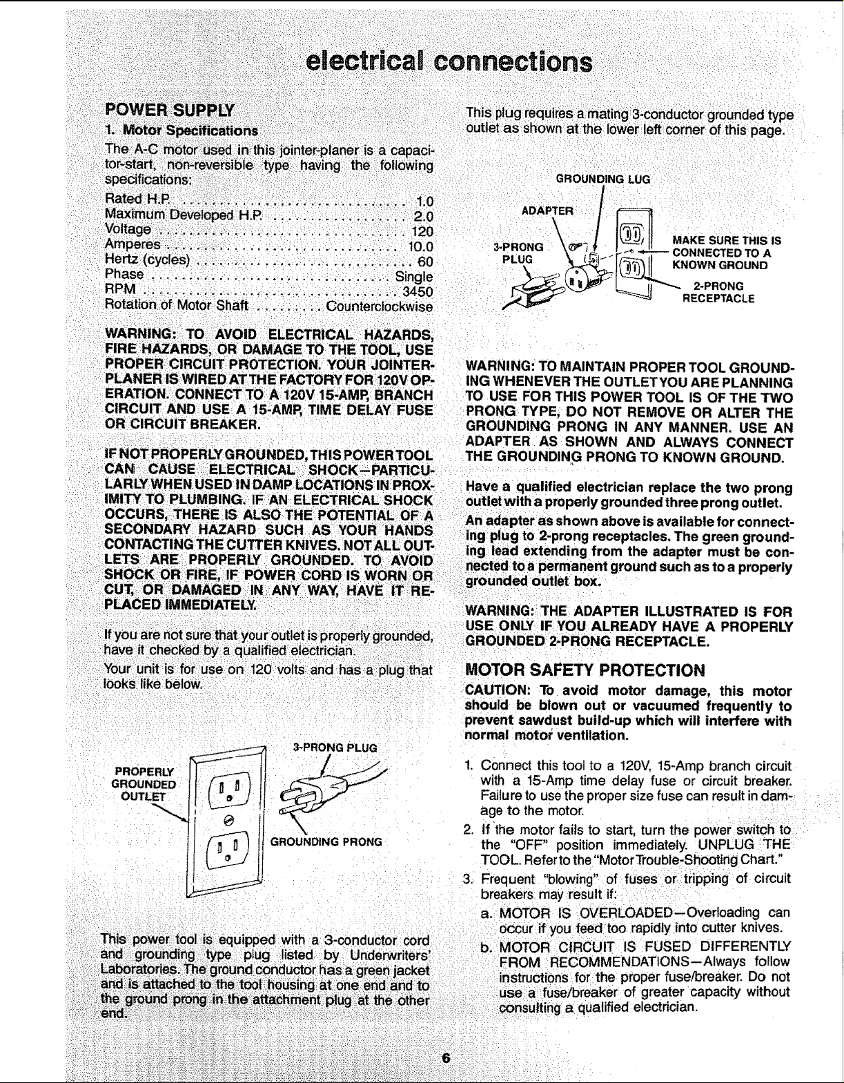
FIRE HAZARDS, OR DAMAGE TO THE TOOL, USE
::PROPER:CIRCUIT PROTECTION. YOUR JOINTER,
PLANER ISWIRED ATTHEFACTORY F0R 120V OP-
ERATION. CONNECTTO::A i20V 15-AMP, BRANCH
CIRCUIT AND USE::A: 15-AMP, TIME DELAY FUSE
OR CIRCUIT BREAKER.
IF NOT PROPERLYGROUNDED, THIS POWER TOOL
CAN ,CAUSE ELECTRICAL SHOCK,PARTICU.
WARNING: TO MAINTAIN PROPER TOOL GROUND-
ING WHENEVER THE OUTLET YOU AR EPLANNING
TO USE FOR THIS POWER TOOL IS OF THE TWO
PRONG TYPE, DO NOT REMOVE OR ALTER THE
GROUNDING PRONG IN ANY MANNER. USE AN
ADAPTER AS SHOWN AND ALWAYS CONNECT
THE GROUNDING PRONG TO KNOWN GROUND.
: looks;like beloW,
PROPERLY
GROUNDED
OUTLET
3-PRONG PLUG
GROUNDING PRONG
a' 3-conductor cord
Underwriters_
CAUTION: To avoid motor damage, this motor
should be blown out or vacuumed frequently to
prevent sawdust build-up which will interfere with
normal motor ventilation.
Connect this tool to a 120V, 15-Amp branch circuit
with a 15-Amp time delay fuse or circuit breaker.
Failure to use the proper size fuse can result in dam*
age to the motor.
,
If the motor fails to start, turn the power switch to
the "OFF" position immediately. UNPLUG THE
TOOL. Refer to the "MotorTrouble-Shooting Chart."
;
Frequent "blowing':' of fuses or tripping of circuit
breakers may result if:
a._MOTOR IS OVERLOADED--Overloading can
oCcur if you feed too rapidly into cutter knives.
b,: MOTOR:CIRCUIT IS FUSED DIFFERENTLY
:FROM RECOMMENDATIONS--Always follow
: instructions for the proper fuse/breaker. Do not
; :use:a fuse/breaker of greater capacity without
consulting a qualified electrician.

c. LOWVOLTAGE.Althoughthemotorisdesigned:: WIRE: SIZES
f0i'i operation:on the voltage and frequency The use of any extension cord wilt cause some loss of
specified:on motor nameplate, normal loads will power, To keep this to a minimum and to prevent over-
be handled safelyonvoltages notmore than 10% heating and motor burn-out, use the table below to
above or below the nameplate voltage. Heavy
loads, however, require that voltage at motor ter-
minals equals the voltage specified on name-
plate:
4. Most motor troubles may betraced to loose or incor-
rect connections, overloading, reduced input voltage
(such as small size wire in the supply circuit) or to
overly long supply circuit wire. Always check the
connections, the load and the supply circuit
whenever motor fails to perform satisfactorily. Check
wire sizes and length with the Wire Size Chart shown
to the right.
determine the minimum wire size (A.W.G,) extension
cord. Use only 3 wire extension cords which have 3
prong grounding type p_ugs and 3-pole receptacles
which accept the tools plug.
CAUTION: For circuits that are farther away from
electrical service box, the wire size must be in-
creased proportionately in order to deliver ample
voltage to the saw motor.
Length of the
Conductor
0-25 Ft. No. 16
26.50 Ft. No. 14
51-100 Ft. No, 12
Wire Sizes Required
(American Wire Gauge Number)
120V Lines
• i¸¸¸ :.... • •
7
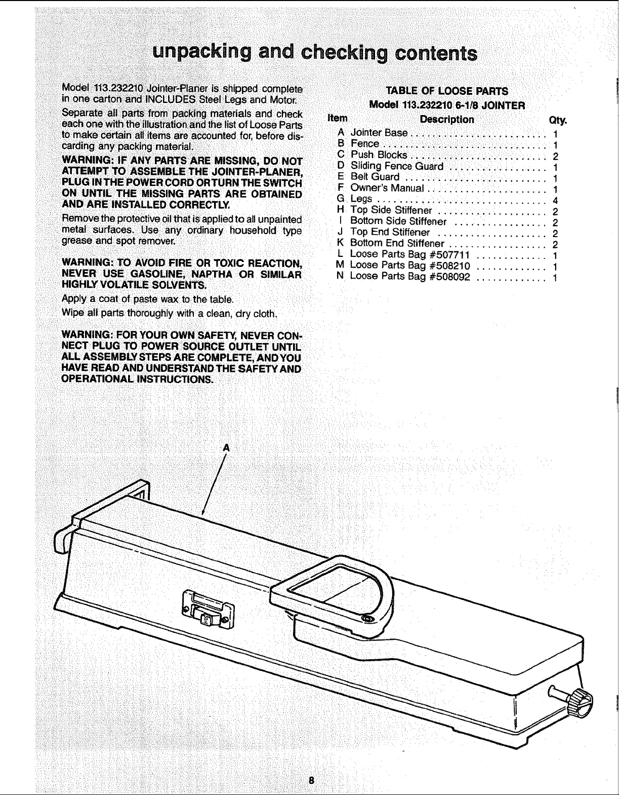
E MISSINGPARTSAREOBTAINED
ICORRECTLY.
0ilthat:isappliedto allunpainted
TOXIC REACTION.
E,:_NAPTHA OR SIMILAR
SOL:VE S;
::Applya coat of paste:wax t0the table.
Wipe all partsth0rough y w tha clean, dry cloth.
WARNING:- FOR:YOUR OWN SAFETY, NEVER CON-
NECTP LUG::TOi_POWER SOURCE 0 UTLET UNTIL
ALLASSEMBLY STEPS ARE COMPLETEiANDYOU
HAVE READiANDUNDERSTAND THE SAFEW AND
OPERATIONAL :iNSTRUCTIONS, i
,el:1i3;232210! 6,1/8 :JOINTER
item ; :::Description _ Qty.
A JointerBase,,;!i. ;.., ..; ....... 1
B Fence .:; ,.:i.. , ...................... 1
C;Push Bocks...:ii.::i_.i :..:... ;i; ;... , 2
D Siding Fence Guard... ;.....: ........ 1
E Belt Guard .......................... t
F Owner's Manual ...................... 1
G Legs ................... ............ 4
H Top Side Stiffener .................... 2
I Bottom Side Stiffener ................. 2
J Top End Stiffener .................... 2
K Bottom End Stiffener .................. 2
L Loose Parts Bag #507711 ............. 1
M Loose Parts Bag #508210 ............. 1
N Loose Parts Bag #508092 ............. 1
: L--,! ¸: _ • :•: •• •• / : . .
L•_••I•/
E
\
K
i' ;•••i i•'_::••i•¸¸I¸:•:•ii_i!!i:¸•_•_•
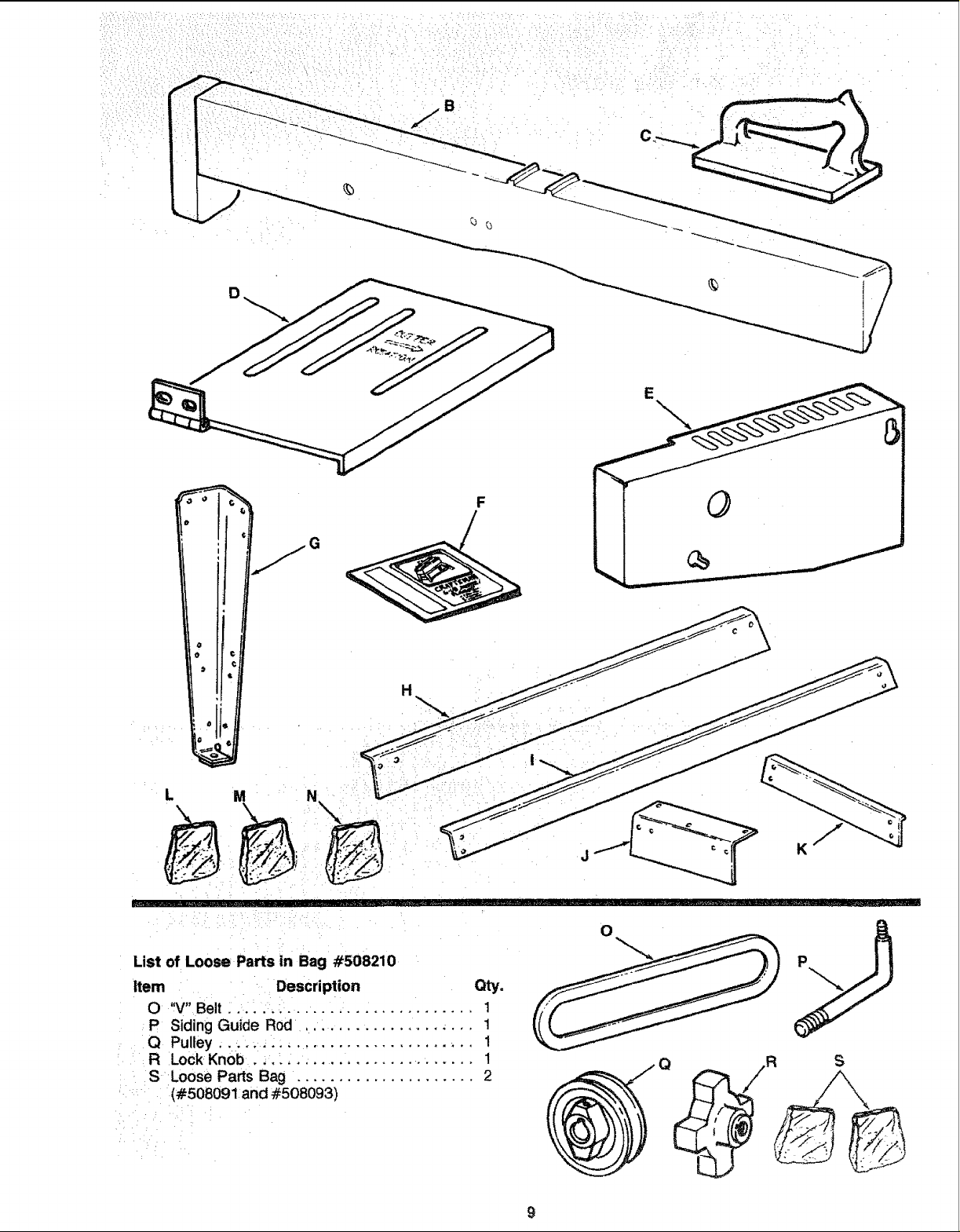
List of Loose Parts in Bag #508210
Item Description Qty.
O ,V"Belt .. i. ..................... 1
P Siding Guide Rod. ............... ,... 1
Q Pulley.... :: ....................... 1
R Lock Knob ._.: ........ ................ 1
:S iLoose Parts Bag. .................... 2
: (#508091and #508093)
O
9
G
0
i i
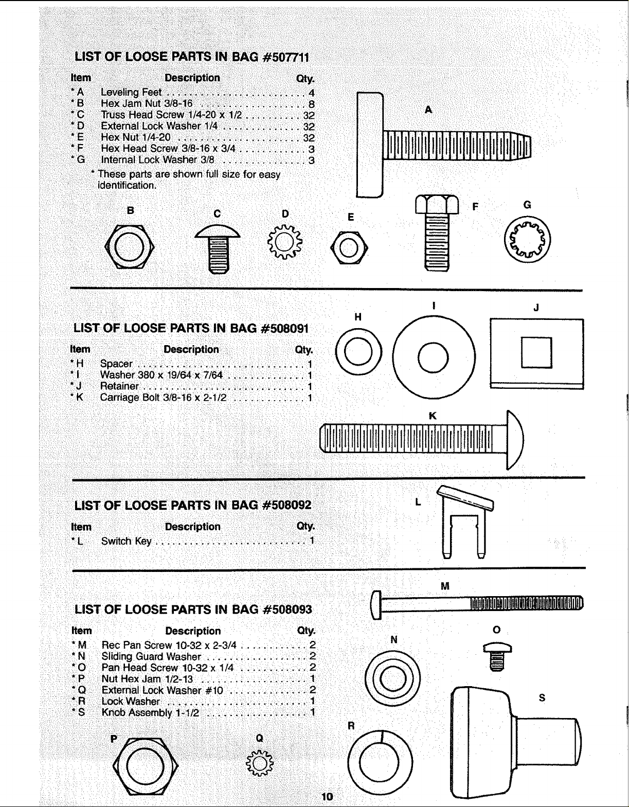
LIST OF LOOSE PARTS: IN BAG #508091
Item :i:_::i:i :Description: : Qty.
_H .::::Spacer ::::.!__::_. ill::. ...... ..... :. i
:i Washer380x 19/64x7/64, .:. .....:,,:;;.. 1
*3 Retainerli ,. _/,:!_:i ,.,' i
*::K . Carriage:Bolt3/8-16 x2.1/2, i..... :.;:. ;_ 1
: L
Description
!:*L
Switch Key, ........... .:.....i::. ..... -.. 1:......
O
iJJ
ii i iii ii
!
i[]
M
LIST OF LOOSE PARTS IN BAG #508093
Item Description Qty.
G
N
,Lllltppnltl_lllWUlWllimltlli!g
0
S
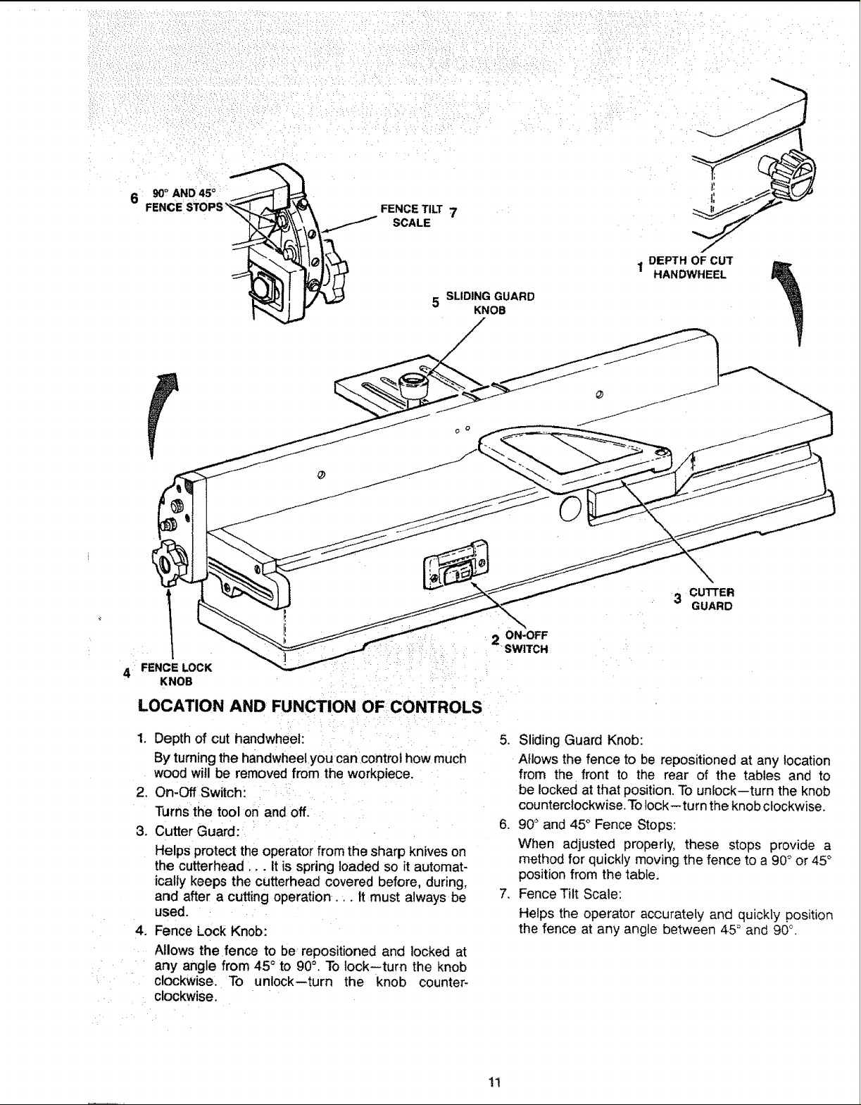
90° AND 45 °
FENCE STOPS _
FENCETI_ 7
SCALE
5 SLIDING GUARD
KNOB
1 DEPTH OF CUT
HANDWHEEL
3 CUTTER
GUARD
_: :i_::!!: ::;: i
4 FENCELOCK
KNOB : _
LOCATION AND FUNCTION OFCONTROLS
1. Depth of cut handwheeh i: : _ _:
By,turningthe handwheel you can controihow much
wood will be removed from the workpiece.
2. On-Off Switch_ _:
Turns the tool on and off.
3. Cutter Guard:
Helps protect the operator from the sharp knives on
the cutterhead,. It is spring loaded so it automat-
ically keeps the cutterhead covered before, during,
and after a cutting operation,.. It must always be
used, :
4. Fence Lock Knob:
Allows the fence to be: repositioned and locked at
any angle from 45 °to 90°. To lock--turn the knob
clockwise:. To unlock--turn the knob counter-
clockwise.
2 ON-OFF
SWITCH
5. Sliding Guard Knob:
Allows the fence to be repositioned at any location
from the front to the rear of the tables and to
be locked at that position. To unlock--turn the knob
counterclockwise.To lock--turn the knob clockwise,
6. 90° and 45° Fence Stops:
When adjusted properly, these stops provide a
method for quickly moving the fence to a 90° or 45°
position from the table,
7, Fence Tilt Scale:
Helps the operator accurately and quickly position
the fence at any angle between 45" and 90°.
11
EDGE:OF: : : :
NCH THICK: i :
...... _ : : PERFECTLY STRAIGHT
• ....... ...... :\
_::::: : ,sCREWDRiVEF \_
/ :
"_:'/ i -
il _ : _ :
- _ ..... _ I'#'il LINE ON BOARD /
I : : :7116'!SOCKET _ : ' L!_ ALONG THIS EDGE '_ I
, .... ,,2SOC<E, . ..... _ , ..... ,\J, --
I :6_':SOCKET EXTENSION 7ii6": OPEN END:WRENCH [
I 3/4"OPENENDWRENCH
9/16" SOCK_ '% : iN
1/2":OPEN END WRENCH SHOULD BE NO GAP OR OVERLAP HERE WHEN
9/16;';OPEN END WRENCH SQUARE IS FLIPPED OVER IN DOTTED POSITION
THEJOINTER PLANER;:::::::!
;_ COMBINATION SQUARE I(____ I: : : ! /
....... I[_, ,'_'-_ DRAW LIGHT ..... i /
I /
: .... I
LEVELING FOOT
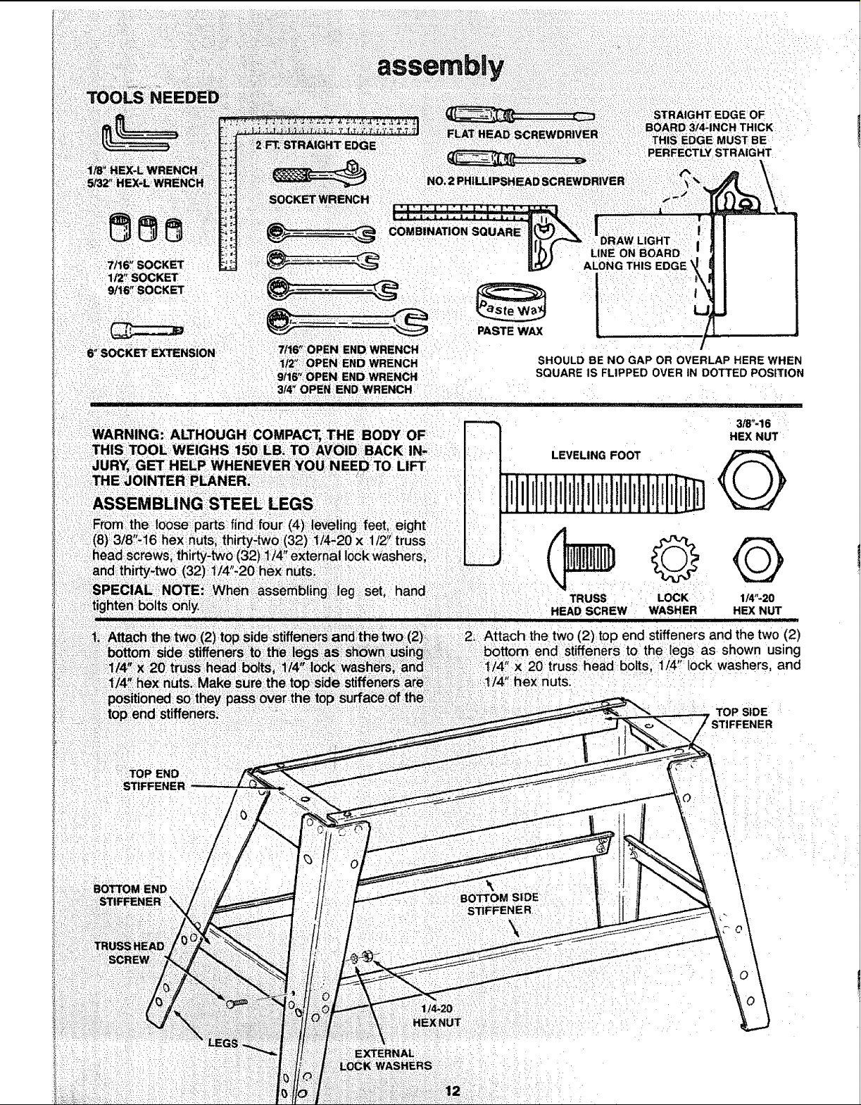
©Q
leg set, hand
TRUSS
HEAD SCREW
LOCK 114"-20
WASHER HEX NUT
3/8"..16
HEX NUT
Q
STII
STIFFENER
\
j,ll,_l
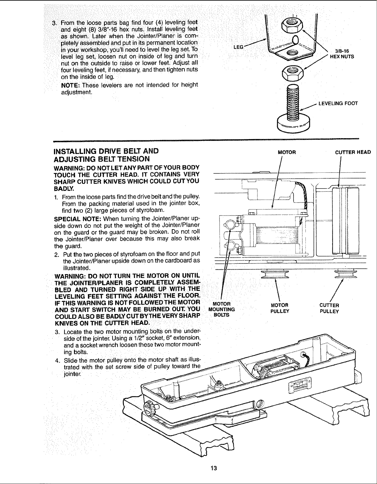
INSTALLING DRIVE BELT AND
ADJUSTING BELT TENSION
WARNING: DO NOT LETANY PART OFYOUR BODY
TOUCH THE CUTTER HEAD. tT CONTAINS VERY
SHARP CUTTER KNIVES WHICH COULD CUT YOU
BADLY.
1. Fromthe looseparts find the drivebeltand theputiey.
From the packing material used in the jointer box,
find two (2) large pieces of styrofoam.
SPECIAL NOTE: When turning the JointeriPtaner up-
side down do not put the weight of the Jointer/Planer
on the guard or the guard may be broken. Do not roll
the JointedPlaner over because this may also break
the guard.
2. Put the two pieces of styrofoam on the floor and put
the JointeriPlaner upside down on the cardboard as
illustrated.
WARNING: DO NOT TURN: THE MOTOR ON UNTIL
:THE JOINTERiPLANER IS COMPLETELY ASSEM- : : :
BLED AND TURNED RIGHTSIDE: UP WITHiTHE i : i_: :
LEVELING FEET SETTING AGAINSTTHE FLOOR_ :_:
IF THIS WARNING IS NOT FOLLOWED THE MOTOR MOTOR
AND START SWITCH MAY BE BURNED OU_'YOUI MOUNTING
COULD ALSO BE BADLYCUT BYTHE VERY SHARP = BOLTS
KNIVES ON THE CU_ER HEAD_ :: ', :' :
3. Locate the two motor: mounting bolts on the under-
side ofthe j0inter. Using a 1/2, _Socket, 6" extension,
and aSocket wrench loosenthese two moto_ mount-
ing bolts. .........
4. Slide the motor: pUiley onto the motor shaft as illus-
trated with the set screw side of pulley toward the
jointer, i
MOTOR CUTTER HEAD
•
MOTOR
PULLEY
CUTTER
PULLEY
13
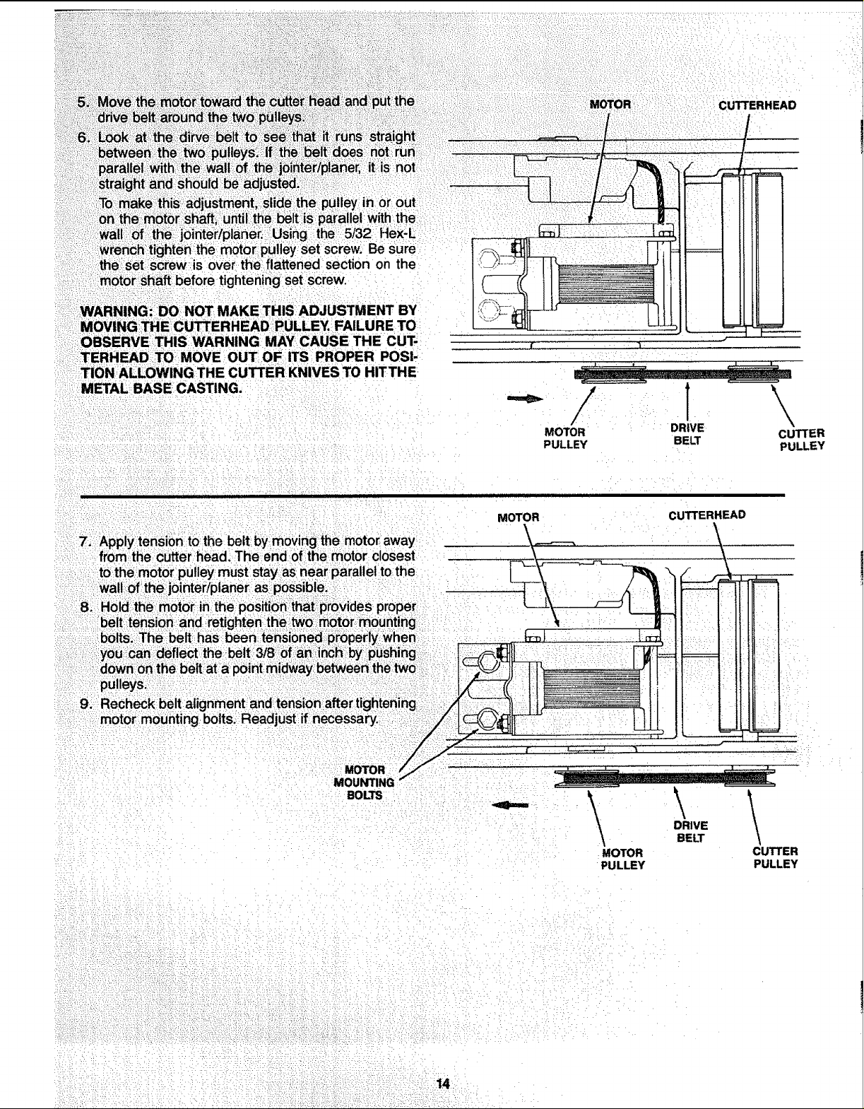
screw,isover the fl, on the
!::motor stiaft before tightening set screw.
THISAOJUST.E.T.V
MoVING!THE CUTTERHEAD!PULLEY. FAILURE TO
OBSERVE THiS IWARNING MAY CAUSE THE CUT-
TERHEAD TO MOVE OUT OF ITS: PROPER POSI-
TION ALLOWING THE CUTTER: KNIVES TO HITTHE
'METAL BASE CASTING.
!
BOLTS .
, , , , ,, ,111
MOTOR
.,q_DiIiiNim •
MOTOR DRIVE
PULLEY BELT
CUTTERHEAD
\
DRIVE
BELT
MOTOR
PULLEY
\
CUTTER
PULLEY
CUTTER
PULLEY
•14
 Loading...