

Craftsman 113226423 Owner’s Manual

i i ii ii i,ii ii ii i i
SAVE THIS MANUAL
FOR FUTURE REFERENCE
MODEL NO.
113.226423
BELT AND DISC
SANDER
Serial
Number
Model and serial number
may be found on the back
side of the base,
You should record both
mode! and serial number in
a safe place for future use.
CAUTION:
Read GENERAL
and ADDITIONAL
SAFETY
INSTRUCTIONS
carefully
C F'rs
BELT AND DISC
SANDER
® assembly
• operating
e repair parts
Sold by SEARS, ROEBUCK AND CO., Chicago, IL 60684 U.S.A.
PART NO SP500t _:_;_!_::D t; _. _ ;:

i= ....... i , , , i
FULL ONE YEAR WARRANTY ON CRAFTSMAN BELT AND DISC SANDER
If within one year from the date of purchase, this Craftsman Belt and Disc Sander fails due
to a defect in material or workmanship,: sears will repair it, free of charge.
WARRANTY SERVICE IS AVAILABLE BY RETURNING TH E BELT AND DISC SANDER TO
THE NEAREST SEARS RETAIL/CATALOG STORE OR SERVICE CENTER/DEPARTMENT IN
THE UNITED STATES:
THIS WARRANTY APPLIES ONLY WHIL ETHIS PRODUCT IS IN USE IN THE UNITED STATES.
This warranty gives you specific legal rights, and you may also have other rights which
vary from state to state.
SEARS, ROEBUCK AND CO., Sears Tower, BSC 41-3, Chicago, IL 60684
general safety instructions for power tools
1. KNOW YOUR POWER TOOL
Read and understand the owner's manual and
Iabels affixed to the tool. Learn its application and
limitations as welI as the specific potential hazards
peculiar to this tool.
2. GROUND ALL TOOLS
This tool is equipped with an approved 3-conductor
cord and a 3-prong grounding type plug to fit the
proper grounding type receptacle. The_green con-
ductor in the cord is the grounding wire. Never
connect the green wire to a live terminal.
3. KEEP GUARDS IN PLACE
In working order, and in proper adjustment and
alignment.
4. REMOVE ADJUSTING KEYS AND
WRENCHES
Form a habit of checking to see that keys and
adjusting wrenches are removed from tootbefore
turning it on.
5. KEEP WORK AREA CLEAN
Cluttered areas and benches invite accidents.
Floor must not be slippery due to wax or sawdust.
6. AVOID DANGEROUS ENVIRONMENT
Don't use power tools in damp or wet locations or
expose them to ra_noKeep work area welt lighted.
Provide adequate surrounding work space.
7. KEEP CHILDREN AWAY
All visitors should be kept a safe distance from
work area.
8. MAKE WORKSHOP CHILD-PROOF
--with padlocks, master switches, or by removing
starter keys.
9. DON'T FORCE TOOL
it wilt do the job better and safer at the rate for
which it was designed.
10. USE RIGHT TOOL
Don't force tool or attachment to do a job it was
not designed for.
11. WEAR PROPER APPAREL
Do not wear loose ctothing, gloves, neckties or
jewelry (rings, wrist watches) to get caught in mov-
ingp_.rts.Nonslip footwear isrecommended. Wear
protective hair covering to C0ntain iong ha
12,
USE SAFETY GOGGLES (Head Protection)
Wear Safety goggles _must comply with ANSI
Z87.1 ) at all times Everyday eyeglasses only have
impact resistant lenses_ they are NOT safety gJas-
ses. Also, use face or dust mask if cutting operation
is dusty, and ear protectors (plugs or muffs) during
extended periods of operation,
13.
SECURE WORK
Use clamps or a vise to hold work when practical
It's safer than using your hand. frees both hands
to operate tool.
14. DON'T OVERREACH
Keep proper footing and batance al all times.
15. MAINTAIN TOOLS WITH CARE
Keep tools sharp and clean for best and safest
performance. Follow instructions for lubricating and
changing accessories.
16. DISCONNECT TOOLS
Before servicing; when changing accessories such
as blades, bits, cutters, etc.
17, AVOID ACCIDENTAL STARTING
Make sure switch is in "OFF" position before plug-
ging in.
18. USE RECOMMENDED ACCESSORIES
Consult the owner's manual for recommended ac-
cessories. Follow the Enstructions that accompany
the accessories. The use of improper accessories
may cause hazards.
19, NEVER STAND ON TOOL
Serious injurycould occur if the tool is tipped or if
the cutting tool is accidentally contacted.
Do not store materials above or near the toot such
that it is necessary to stand on the tool to reach
them.
20. CHECK DAMAGED PARTS
Before further use of the tool, a guard or other part
that is damaged should be carefully checked to
ensure that it wilt operate properly and perform its
intended function. Check for alignment of moving
parts, binding of moving parts, breakage of parts,
mounting, and any other conditions that may affect
itsoperation. A guard or other part that is damaged
long sleeves above the elbow.:; : ......, ,...... should be properly repaired or replaced,

21. DIRECTION OF FEED
Feed work into a blade or cutter against the direc-
tion of rotation of the blade or cutter only.
22. NEVER LEAVE TOOL RUNNING UNATTENDED
Turn power off. Don't leave tool until it comes to a
complete stop.
additional safety instructions for beff and disc sander
Safety is a combination of operator common sense and
alertness at all times when the sander is being used.
WARNING: For your own safety, do not attempt to
operate your Belt and Disc Sander until it is com-
pletely assembled and installed according to the
instructions.., and until you have read and under-
stand the following:
Page
1. General Safety Instructions for Power Tools. 2
2. Getting to Know Your Sander ........... 15
3. Basic Operation ....................... 17
4. Maintenance .......................... 20
5. Stability of Machine
If there is any tendency for the machine to tip over
or move during certain operations such as when
sanding long heavy boards, the sander should be
bolted down.
6. Location
The machine should be positioned so neither the
operator nor a casual observer is forced to stand
in line with the sanding belt or disc. This machine
is intended for indoor use only.
7. Kickback
When sanding on the Disc, always apply the work-
piece left of center to the left side of the disc. Ap-
plying the workpiece to the right side could cause
it to fty up (kickback) which could be hazardous.
8. Protection: Eyes, Hands, Face, Ears and Body
a. Always wear safety goggles (not glasses)
that comply with ANS1 Z87.1, Wear face shield
if operation is dusty, Wear ear plugs or muffs
during extended periods of operation, Do not
wear gloves, jewelry or watches. Roll long
sleeves above the elbow. Tie back long hair.
b. Do not sand pieces of material too small to
hold by hand.
c. Avoid awkward hand positions, where a
sudden slip could cause a hand to move
intosanding disc or belt.
d. Neverclimbonthe machine.
e. Never turn your Sander "ON" before clear-
ing the belt table and worktable of all ob-
jects.
f. Make sure the sanding belt runs in the right
direction (directional arrow on back side of
belt). Always have the tracking adjusted cor-
rectly so that the belt does not run off the pul-
leys.
g. Hold the work firmly when sanding on the belt
and against the worktable when sanding on
the disc.
h. Always adjust the worktable to within a
maximum of 1/16-inch of the sanding disc
or belt.
i. When sanding a large piece of material, pro-
vide additional support attable height.
j. Never leave the machine work area when
the power is on, before the machine has
come to a complete stop, or without remov-
ingand storing the switch key.
k. Do not perform layout, assembly or setup
work on the table while the sander is
operating.
1. Turn sander "OFF" and remove plug from
power supply outlet before installing or
removing an accessory.
m Use only RECOMMENDED ACCESSORIES
listed on page 2I.
9_
If any part of this Belt and Disc Sander should
break, bend, or fail in any way or any electrical
component fail to perform properly, or if any is
missing, shut off power switch, remove power sup-
ply cord from power supply and replace damaged
missing and/or failed parts before resuming oper-
ation.
10.
Do not sand with the workpiece unsupported. Sup-
port it with the backstop or worktable. The only
exception is curved work performed on outer end
of belt (idler pulley).
11. To avoid entanglement in spindle, do not operate
sander with sanding plate and/or guard removed.
CAUTION: This Belt and Disc Sander is designed
to sand wood or wood like products only. Attempts
to sand or grind other materials could result in fire,
injury or damage to the product.
additional safety instructions for belt and disc sander
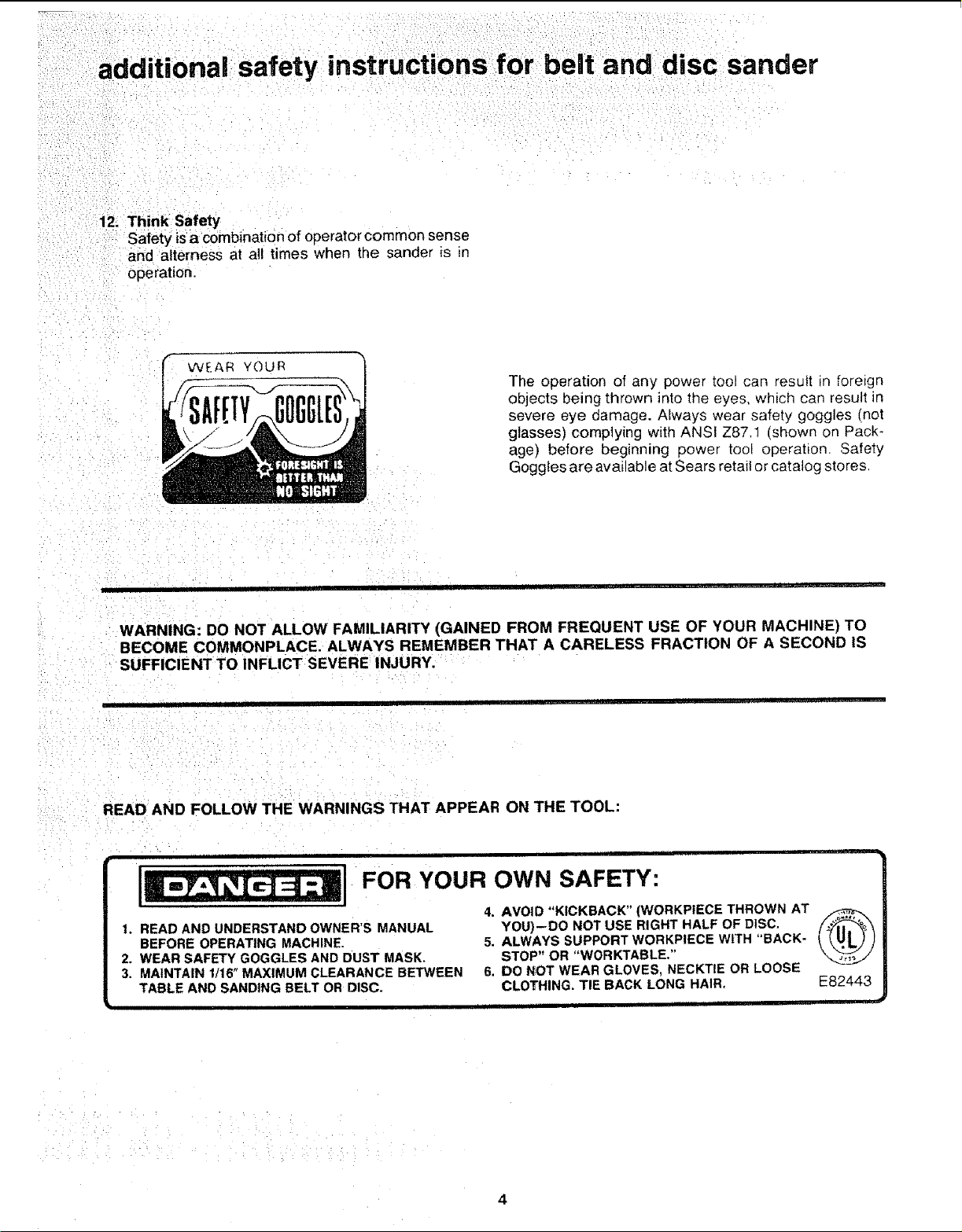
12; Think Safety
Safety is a combination of operator common sense
and alterness at all times when the sander is in
operation.
The operation of any power tool can "es@t in foreign
objects being thrown into the eyes, which can result in
severe eye damage. Always wear safety goggles (not
glasses) complying with ANSI Z87,1 (shown on Pack _
age) before beginning power tool operation. Safety
Goggles are available at Sears retail or catalog store&
i I I i • • '
WARNING: DO NOT ALLOW FAMILIARITY (GAINED FROM FREQUENT USE OF YOUR MACHINE) TO
BECOME COMMONPLACE, ALWAYS REMEMBER THAT A CARELESS FRACTION OF A SECOND IS
SUFFICIENT TO INFLICT SEVERE INJURY.
• I ll[[J .L [[ I ' ii I
READ AND FOLLOW THE WARNINGS THAT APPEAR ON THE TOOL:
] i ii
FOR YOUR OWN SAFETY:
4. AVOID "KICKBACK" (WORKPIECE THROWN AT
1, READ AND UNDERSTAND OWNER'S MANUAL
BEFORE OPERATING MACHINE.
2. WEAR SAFETY GOGGLES AND DUST MASK.
3. MAINTAIN 1/16" MAXIMUM CLEARANCE BETWEEN
TABLE AND SANDING BELT OR DISC.
YOU)--DO NOT USE RIGHT HALF OF DISC,
5. ALWAYS SUPPORT WORKPIECE WITH "BACK-
STOP" OR "WORKTABLE,"
6. DO NOT WEAR GLOVES, NECKTIE OR LOOSE
CLOTHING. TIE BACK LONG HAIR. E82443
motor
specifications and electrica requirements
This machine is designed to use, and is equipped with,
a 3450 RPM motor, It is wired for operation on 110-120
volts, 60 Hz., alternating current. (TOOL MUST NOT
BE CONVERTED TO OPERATE ON 230 VOLT).
For replacement motor refer to parts list isthis manual.
CONNECTING TO POWER SUPPLY OUTLET
This machine must be grounded while in use to protect
the oeprator from electric shock.
Plug power cord into a 110-120V properly grounded
type outlet protected by a 15-amp. fuse or circuit
breaker.
WARNING: Do not permit fingers to touch the ter-
minals of plugs when installing or removing the
plug to or from the outlet.
WARNING: If not properly grounded this power
tool can cause an electrical shock, particularly
when used in damp locations close to plumbing. If
an electrical shock occurs there is the potential of
a secondary hazard such as your hands contacting
the sanding surface.
If power cord is worn or cut, or damaged in any way,
have it replaced immediately.
If your unit is for use on 110-120 volts, and has a plug
that looks like below.
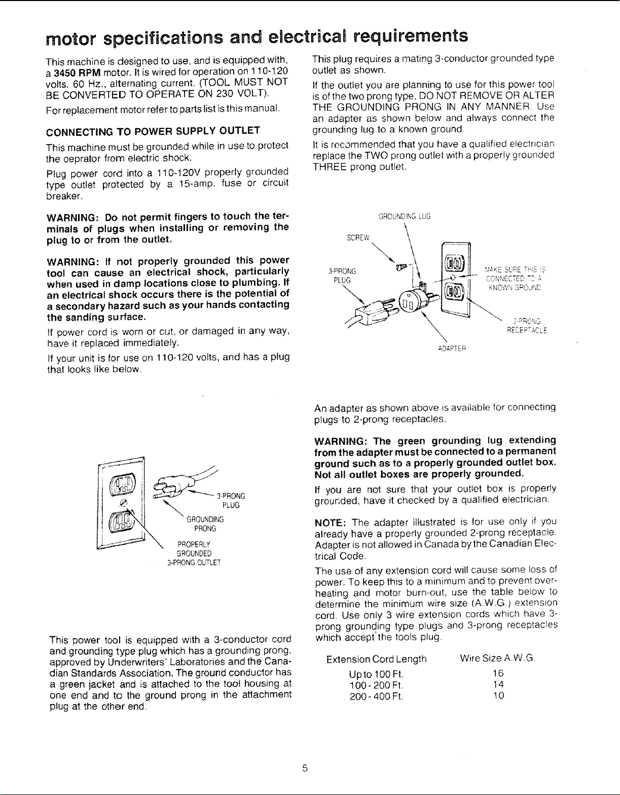
This plug requires a mating 3-conductor grounded type
outlet as shown.
If the outlet you are planning to use for this power tool
is of the two prong type, DO NOT REMOVE OR ALTER
THE GROUNDING PRONG IN ANY MANNER. Use
an adapter as shown below and always connect the
grounding lug to a known ground.
It is recommended that you have a qualified electrician
replace the TWO prong outlet with a properly grounded
THREE prong outlet.
GROUNDING LUG
SCREW \
3-PRONG _1_ _J_,KESURE TH_S 5
"x HECEPT,_CLE
ADAPTER
_3-PRONG
"_'-,, GROUNDINGLUG
PRONG
_ PROPERLY
GROUNDED
3-PRONGOUTLET
This power tool is equipped with a 3-conductor cord
and grounding type plug which has a grounding prong,
approved by Ur_derwriters' Laboratories and the Cana-
dian Standards Association. The ground conductor has
a green jacket and is attached to the toot housing at
one end and to the ground prong in the attachment
plug at the other end,
An adapter as shown above is available for connecting
plugs to 2-prong receptacles.
WARNING: The green grounding lug extending
from the adapter must be connected to a permanent
ground such as to a properly grounded outlet box.
Not all outlet boxes are properly grounded.
If you are not sure that your outlet box is properly
grounded, have it checked by a qualified electrician
NOTE: The adapter illustrated is for use only if you
already have a properly grounded 2-prong receptacle.
Adapter is not allowed in Canada by the Canadian Elec*
tricaf Code.
The use of any extension cord will cause some ioss of
power, To keep this to a minimum and to prevent over-
heating and motor burn-out, use the table below to
determine the minimum wire size (A.W,G.) extension
cord. Use onty 3 wire extension cords which have 3-
prong grounding type plugs and 3-prong receptacles
which accept the tools plug.
Extension Cord Length Wire Size A,W.G.
Upto 100 Ft. !6
100 - 200 Ft. 14
200 - 400 Ft. t 0
: UnpackingAndCheckingContents....... __._.. 6
Be!t Table Stop .......................... 18
Surface Sanding on Sanding Belt ........... 18
Mounting Belt and Disc Sander to Workbench . 7
Clamping Bell and Disc Sander to Workbench .. 8
Installing Timing Belt ...................... 9
Installing Pulley Cover .................... t0
Installing Sanding Disc Plate ............... 10
Installing Backstop ....................... 11
Installing Table Assembly .................. 12
End Sanding on the Sanding Belt ........... 18
Sanding Curved Edges ................... 19
Maintenance .............................. 20
Lubrication ............................. 20
Troubleshooting ........................... 21
Recommended Accessories .................. 2t
Repair Parts .............................. 22
Squaring Table Assembly .................. 13
, n u, Jl ..#,€_ • . .....
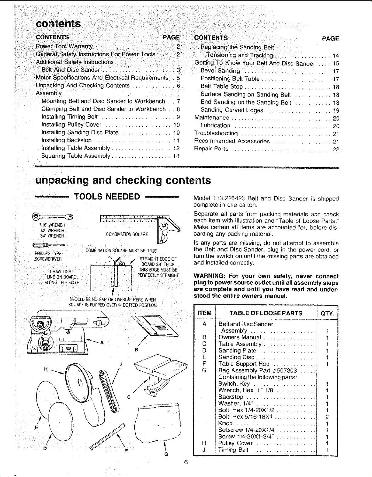
unpacking and checking contents
TOOLS NEEDED _ Model II3,226423 Belt and Disc Sander is shipped
complete in one carton.
_=_--;- ' _ each item with illustration and "Table of Loose Parts."
7it6"WaENCH " (_) Make certain all items are accounted for, before dis-
I/2" WREI_H
=
3/4_WRENCH carding any packing material.
_: ts any parts are missing, do not attempt to assemble
PHILLIPStYPE : COMBINATIONSQUAREMUSTBETRUE the Belt and Disc Sander, plug in the power cord, or
; SCREWDRIVER STRAIGHTEDGEOF turn the switch on until the missing parts are obtained
: DRAWLIGHT THISEDGEMUSTBE
::: LINE:ONBOARD PERFECTLYSTRAIGHT WARNING: For your own safety, never connect
: : i : A_ONGq'HSEOGE plug to power source outlet until all assembly steps
: : .... ; are complete and until you have read and under-
SHOULDBENOGAPOROVERLAPHEREWHEN stood the entire owners manual.
SQUAREIS FLIPPEDOVERtNDOTTEDPOSITION i:
: ; -- ..... ITEM TABLE OF LOOSE PARTS QTY.
__ Separate atl parts from packing materials and check
BOARD 3!4" THICK and installed correctly.
A Belt and Disc Sander
Assembly ..................... !
B Owners Manual ................. 1
C Table Assembly ................. 1
D Sanding Plate .................. 1
E Sanding Disc ................... t
F Table Support Rod .............. I
G Bag Assembly Part #507303 .....
Containing the following parts:
Switch, Key ................... 1
Wrench, Hex "L" I/8 ............ 1
Backstop ..................... t
Washer, 1/4" . ................. 1
Bolt, Hex 1/4-20X1/2 ............ 1
Bolt, Hex 5/16-t8Xl ............ 2
Knob ........................ 1
Setscrew 1/4-20Xt/4" . .......... t
Screw 1/4-2OXl-3/4" . ........... 1
H Pulley Cover .................. !
J Timing Belt ................... t
assembly
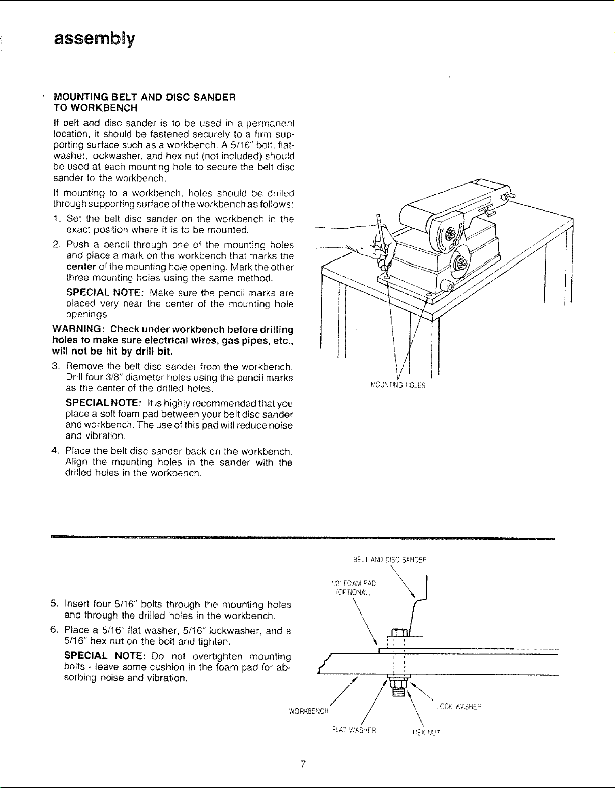
MOUNTING BELT AND DISC SANDER
TO WORKBENCH
If belt and disc sander is to be used in a permanent
location, it should be fastened securely to a firm sup-
porting surface such as a workbench. A 5/16" bolt, flat-
washer, Iockwasher, and hex nut (not included) should
be used at each mounting hole to secure the belt disc
sander to the workbench.
If mounting to a workbench, holes should be drilled
through supporting surface of the workbench as follows:
1. Set the belt disc sander on the workbench in the
exact position where it is to be mounted,
2, Push a pencil through one of the mounting holes
and place a mark on the workbench that marks the
center of the mounting hole opening. Mark the other
three mounting hotes using the same method.
SPECIAL NOTE: Make sure the pencil marks are
placed very near the center of the mounting hole
openings,
WARNING: Check under workbench before drilling
holes to make sure electrical wires, gas pipes, etc.,
will not be hit by drill bit.
3. Remove the belt disc sander from the workbench.
Drill four 3/8" diameter holes using the pencil marks
as the center of the drilled holes.
SPECIAL NOTE: It is highly recommended that you
place a soft foam pad between your belt disc sander
and workbench. The use of this pad will reduce noise
and vibration.
4. Place the belt disc sander back on the workbench.
Align the mounting holes in the sander with the
drilled holes in the workbench.
MOUNTING HOLES
.
Insert four 5/16" bolts through the mounting holes
and through the dritled holes in the workbench.
6,
Place a 5/16" flat washer, 5116" lockwasher, and a
5/16" hex nut on the bolt and tighten,
SPECIAL NOTE: Do not overtighten mounting
bolts - leave some cushion in the foam pad for ab-
sorbing noise and vibration.
I!2' FOA_ PAD X,X_. J
/OPTIONAL
/ ,
WORKBENCH
BELT AND DISC SANDER
i
assembly
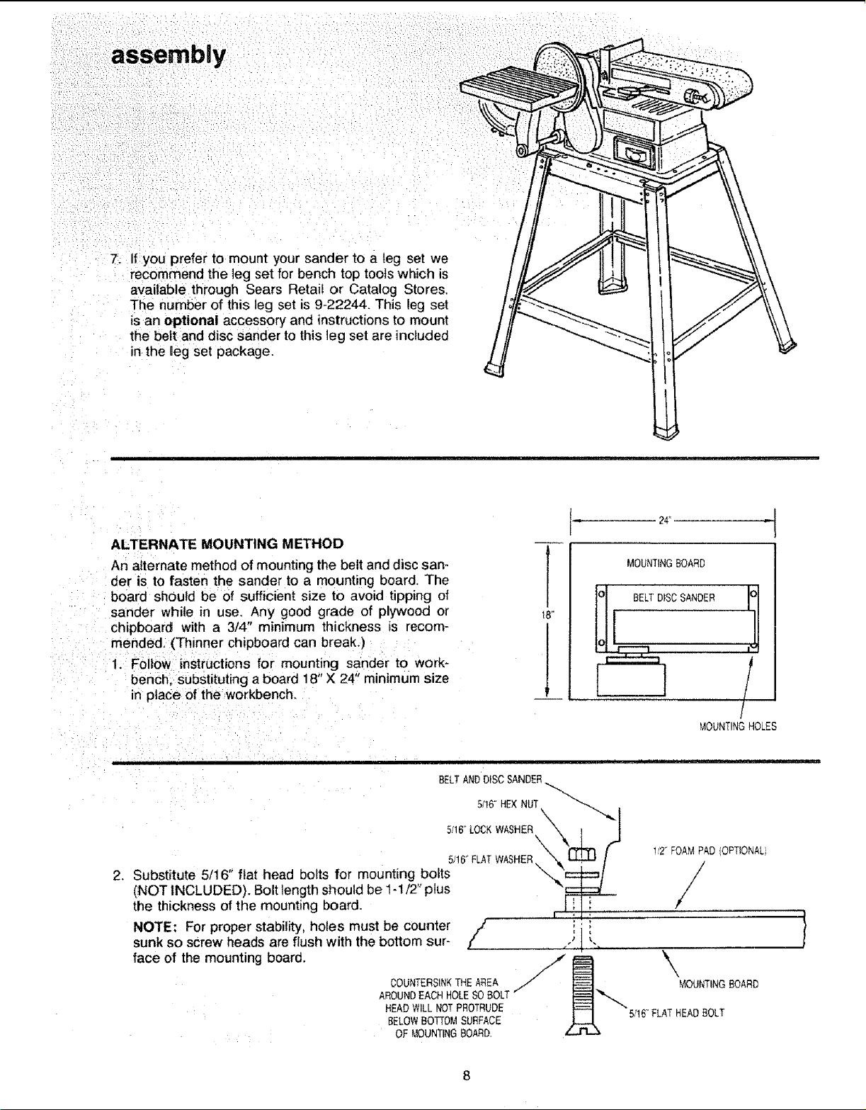
7. If you prefer to mount your sander to a leg set we
recommend the leg set for bench top tools which is
available through Sears Retail or Catalog Stores,
The number of this leg set is 9-22244. This leg set
is an optional accessory and instructions to mount
the belt and disc sander to this leg set are included
in the leg set package.
ALTERNATE MOUNTING METHOD
An alternate method of mounting the belt and disc san-
der is to fasten the sander to a mounting board. The
board should be of sufficient size to avoid tipping of
sander while in use. Any good grade of plywood or
ch_pboard with a 3/4" minimum thickness is recom-
mended. (Thinner chipboard can break.)
1, Follow instructions for mounting sander to work-
bench, substituting a board 18" X 24" minimum size
in place of the workbench.
BELTAND DISCSANDER
5/!6" HEXNUT.Nk_k_._.,"
:::::::::::\' Y
2,
Substitute 5/16" flat head bolts for mounting boits "_,_'_:_===1
(NOT INCLUDED). Bolt length should be 1-1/2 plus _'_
the thickness of the mounting board. I ! 1i
NOTE: For proper stability, holes must be counter /" i ",
sunk so screw heads are flush with the bottom sur- /' , .J ] _.,
face of the mounting board.
COUNTERSINKTHEAREA
AROUND EACH HOLE SO BOLT
HEADWILLNOTPROTRUDE
BELOWBOl-fOMSURFACE
OFMOUNTINGBOARD.
t
[
18"
, , I , ", ,"
24'
MOUNTING BOARD
/
MOUNTINGHOLES
1_2"FOAM PAD OPTIONAL
/
/
\
MOUNTINGBOARD
5;t6"FLATHEADBOLT
 Loading...