

Craftsman 113225930, 113225900 Owner’s Manual
MODEL NO.
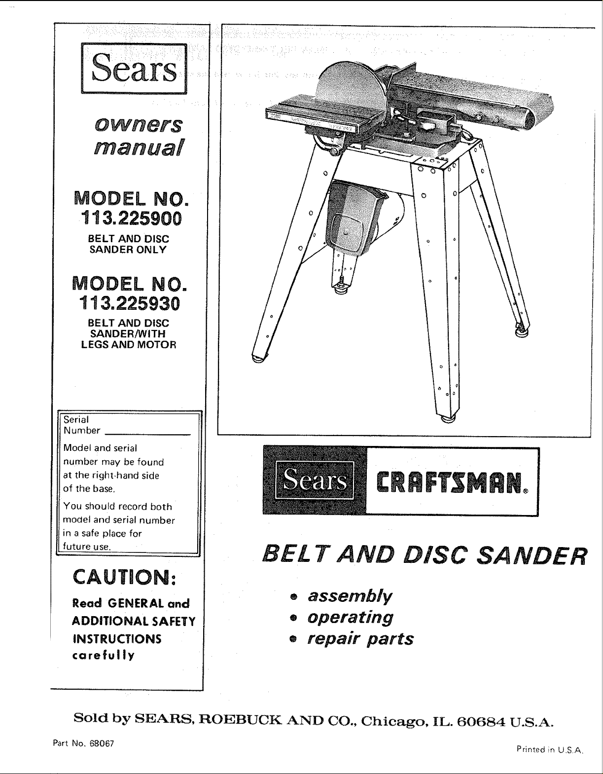
113.225900
BELT AND DISC
SANDER ONLY
MODEL NO.
113.225930
BE LT AND DISC
SANDER!WITH
LEGS AND MOTOR
Serial
Number
Model and serial
number may be found
at the right-hand side
of the base.
C nFTSMR
You should record both
model and serial number
in a safe place for
future use.
BEL T AND DISC SANDER
CAUTION:
Read GENERAL and
ADDITIONAl. SAFETY
INSTRUCTIONS
carefully
Sold by SEARS, ROEBUCK AND CO., Chicago, IL. 60684 U.S.A.
Part No. 68067 Printed in U,S.A,
® assembly
. operating
e repair parts

FULL ONE YEAR WARRANTY ON CRAFTSMAN BELT AND DISC SANDER
This warranty gives you specific legal! rights, and you may also have other rights which vary from state to
state:,
SEARS. ROEBUCK AND CO.. Dept. 698/731A. Sears Tower, Chicago, I L 60684
general safety instructions for power
1, KNOW YOUR POWER TOOL
Read and understand the owner's manual and labels
affixed to the toot, Learn its application and limitations as
well as the specific potential hazards peculiar to this tool.
2. GROUND ALL TOOLS
This toot is equipped with an approved 3-conductor
€o_d arid a 3-prong grounding type plug to fit the proper
grounding type receptacle. Th =. green conductor in the
cord is the grounding wire, Never connect the green wire
to a live terminal.
3, KEEP GUARDS IN PLACE
- in working order, and in proper adjustment and align-
ment.
4, REMOVE ADJUSTING KEYS AND WRENCHES
Form habit of checking to see that keys and adjusting
wrenches are removed from tool before turning it on.
5. KEEP WORK AREA CLEAN
Ciuttered areas and benches inwte accidents. Floor
must not be slippery due to wax or sawdust.
6: AVOID DANGEROUS ENVIRONMENT
Don't use power tools in :damp orwet tocatio ::::::::::::::::::::::::::::: RECOMMENDED ACCESSORIES
;_ose them to rain. Keep work area well lighted. P:t6:_i_le .... Consult the owner's manual for recommended accessories.
adequate surroundingw0rk space,, .....
.
KEEP CHILDREN AWAY
All visitors should be kept a safe distance from worl(:area:
n r ..................18 USE
i:::::iii:i::!9:iNEVER STAND ON TOOL
8. MAKE WORKSHOP KID-PROOF
with padlocks, master swmtches, or by removing starter
keys.
9. DON'T FORCE TOOL
I1 wdl do the job better and safer at the rate for which
_t was desngned
10. USE RIGHT TOOL
Don't force too! or attachment to _o a ?oh _t was not
designed for
11. WEAR PROPER APPAREL
Do not wear loose clothing, gloves, neckties or jewelry
{rings, wristwatches) to get caught _n moving pa_'ts
NONSLIP footwear is recommended. Wear protective
hall covering to contain long hair. Roll long sleeves
above the elbow.
12, USE SAFETY GOGGLES (Head Protection)
Wear safety goggles (must comply with ANSI Z87.t) at all
times. Everyday: eyeglasses only have impact resistant
lenses, they are NOT safety glasses. Also, use face or dust
mask if cutting operation is dusty, and ear protectors
(plugs or muffs} during extended periods of operation.
13. SECURE WORK
Use clamps or a vMse to hold work when practical. It's
safer than using your hand, frees both hands to operate
tool.
14. DON'T OVERREACH
Keep proper footing and balance at all times.
15. MAINTAIN TOOLS WITH CARE
Keep tools sharp and clean for best and safest perform_
ance. Follow instructions for lubricating and changing
accessories.
16. DISCONNECT TOOLS
before servicing; when changing accessories such as
blades, bits, cutters, etc.
17. AVOl D ACCIDENTAL STARTING
Make sure Switch is tn "OFF" posntlon before plugging
n
Follow the instructions that accompany the accessories.
The use of improper accessorues may cause hazards.
.: Serious injury could occur if the tool is tipped or if the
cutting tool is accidentally contacted.
Do not store materials above or near the tool such that
it _snecessary to stand on the tool to reach them,
20. CHECK DAMAGED PARTS
Before further use of the tool. a guard or other part that
=s damaged should be carefully checked to ensure that it
will operate properly and perform its intended function
Check for alignment of moving parts, binding of moving
parts, breakage of parts, mounting, and any other con,
dtt=ons that may affect its operation. A guard or other
_)art that is damaged should be properly repaired or
replaced
21. DIRECTION OF FEED
Feed work into a blade or cutter against the d_rect_on of
rotation of the blade or cutter only.
22. NEVER LEAVE TOOL RUNNING
UNATTENDED
Tu=n power off. Don't leave tool until it comes to a
corn _lete stop

Safety is a combination of operator common sense and
alertness at all times when the finishing machine is being
used.
scraps of wood, etc.) except for the workpiece and
related feed or support devices for the operation
planned.
WARNING: FOR YOUR OWN SAFETY, NO NOT
ATTEMPT TO OPERATE YOUR FINISHING
MACHINE UNTIL IT IS COMPLETELY ASSEM-
BLED AND INSTALLED ACCORDING TO THE
iNSTRUCTIONS . .. AND UNTIL YOU HAVE
READ AND UNDERSTOOD THE FOLLOWING.
PAGE
t. General Safety Instructions For Power Tools .... 2
2. Getting To Know Your Sander ............. 18
3. Basic Machine Operation ................. 21
4. Maintenance ......................... 23
5. Stability Of Machine
tf there is any tendency for the machine to tip over or
move during certain operations such as when finishing
long heavy boards, the sander should be bolted down.
6. Location
The machine should be positioned so neither the opera-
tor nor a casual observer is forced to stand in line with
the abrasive belt or disc. This machine i:s intended for
indoor use only.
7. Kickback
Make sure the abrasive belt runs in the right direction°
Atwayshave the tracking adjusted correctly so that the
belt does not run off the pulleys.
g,
Hold the work firmly when finishing on the abrasive
belt and against the worktable when finishing on the
disc.
h.
Always adjust the worktable to withh_ !/16 i_ of the
abrasive disc or belt.
When finishing a large piece of material, make sure it
is supported at table height,
Never leave the machine work area with the power on,
before the machine has come to a complete stop, or
without removing and storing the switch key.
k.
Never operate the machine with protective cover on
the unused shaft end of the motor removed.
9,
If any part of this bett disc sander should break, bend,
or fail in any way or any electrical component fail to
perform properly, or if any is missing, shut off power
switch, remove power supply cord from power supply
and replace damaged missing and/or failed parts before
resuming operation.
10. Read and follow the instructions appearing on label on
the front edge of the sanding table,
When finishing on the Disc, always apply the workpiece
to the "Down Side" of the disc. Applying the work-
piece to the "Up Side" could cause it to fly up
(kickback) which could be hazardous.
8. Protection: Eyes, Hands, Face, Ears, Body
a. Wear safety goggles that comply with ANSI Z87.1-
1968, and a face shield if operation is dusty. Wear
ear plugs or muffs during extended periods of opera-
tion.
b. Do not finish pieces of material too small to hold by
hand.
c. Avoid awkward hand positions, where a sudden slip
could cause a hand to move into the abrasive disc or
belt.
d, Never climb on the machine.
e, Never turn your Sander "'ON" before clearing the
table(s) or work surface(s) of all objects (tools,
1
11, Do not hand hotd the workpiece. Support it with the
backstop or worktab}e. The only exception is curved
work performed on outer end of belt (idler pultey),
12, Do not get fingers near the in-running nip of dust trap
or section of belt where it enters the dust trap,
13. Think Safety,
CAUTION: This machine is not designed for heavy
deburring operations. When finishing ferrous met-
als, sparks will be generated and could cause a
fire. Disconnect any type of dust collecting hose
from the machine. Also remove all traces of wood
dust that may have accumulated inside the dust
traps in the machine.
additional safety instructions
for belt and disc sander
WARNING: THE 2:1/2" MACHINE PULLEY AND
THE 2" MOTOR PULLEY FURNISHED, WILL
RUN THE DISC AT APPROXIMATELY 2700
RPM AND THE BELT AT APPROXIMATELY
2100 (FEET PER MINUTE) WHEN USED WITH A
3450 RPM MOTOR. NEVER SUBSTITUTE OR
WARNING: DO NOT ALLOW FAMILIARITY
(GAINED FROM FREQUENT USE OF YOUR
MACHINE) TO BECOME COMMONPLACE, AL-
WAYS REMEMBER THAT A CARELESS FRAC-
TION OF A SECOND IS SUFFICIENT TO IN-
FLICT SEVERE INJURY.
INTERCHANGE THESE PULLEYS TO INCREASE
THIS SPEED BECAUSE IT COULD BE DANGER-
OUS.
i ........................... ................. '
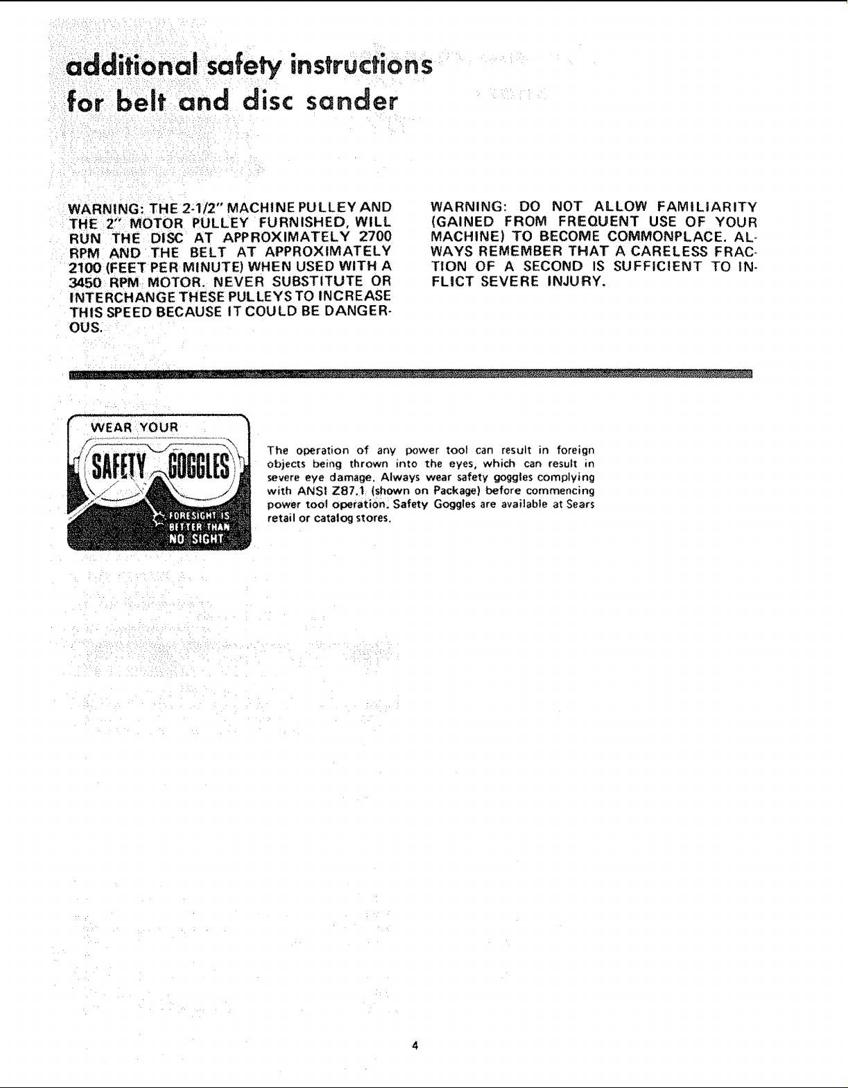
WEAR YOUR
The operation of any power too! can result in foreign
objects being thrown into the eyes, which can result in
severe eye damage, Always wear safety goggles complying
with ANSI ZB7.1 (shown on Package) before commencing
power tool operation: Safety Goggles are available at Sears
retail or catalog stores.
H :•
motor specifications and eledricat requirements
This machine ;s designed to use a 34,50 RPM motor only.
Do not use any motor that runs faster than 3450 RPM.
It {s wired for operation on 110420 volts, 60 Hz, aite__
nating current, iT MUST NOT BE CONVERTED TO
OPERATE ON 230 VOLTS_ EVEN THOUGH SOME OF
THE RECOMMENDED MOTORS ARE DUAL VOLTAGE.
THESE CRAFTSMAN MOTORS HAVE BEEN
FOUND TO BE ACCEPTABLE FOR USE ON
THIS TOOL,
t/2 3450 110. t20 1216
t/2 3450 110-120 1218
3/4 3450 1!0-120 1219
3/4 3450 11O,120 1226
CAUTION: Do not use blower or washing machine motors
or any motor with an automatic reset overload protector
as their use may be hazardous,
CONNECTING TO POWER SOURCE OUTLET
This machine must be grounded while in use to protect
the operator from electric shock.
Plug power cord into a 110.120V properiy grounded type
out_et protected by a 15_amp. dual element time delay or
Circuit.Saver fuse or circuit breaker,
This power tool i_ eqLJipped with a 3.conductor cold and
groundmg tV_; _))Ug which has a grounding prong, _pp_oved
by Underwriters' Labora!or}es arid the Canadian Standards
As'¢ociation. The ground conductor has a green ie..¢ket and
is attached to the toot housing at on_ end af_d to the ground
prong in the attachmer_t plt,g at the Other end.
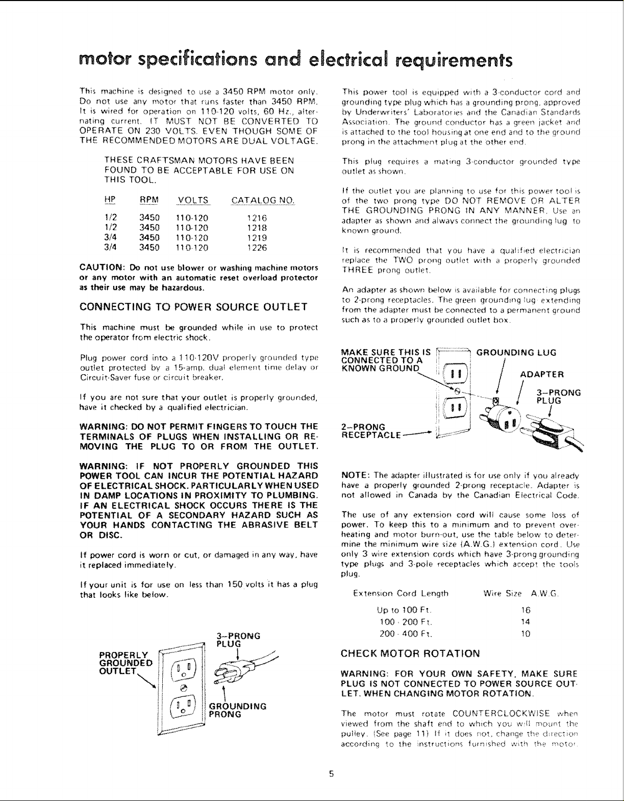
This plug requires a mating 3-conducto. _ grounded type
outlast as shown.
If the outtet yot_ are planning to use for this power tooi is
o¢ the two prong tYi:_ DO NOT REMOVE OR ALTER
THE GROUNDING PRONG IN ANY MANNER. Use an
adapter as shown and always connect the grounding )ug tO
known gro_and,
It is recommended tha! you have a qualified eiectrician
replace the TWO prong outlet with a proper!*,, grounded
THREE prong OUtlet,
An adapter as shown tx.qow is available for cOnr'ecting plugs
to 2-prong receptacie, s. The green gr'oundmg_t_g extending
from the adapter must be connected to a permanent ground
slach a,_ to a proL,_erly grounded outlet box.
If you are not sure that your outlet is properly grounded,
have it checked by a qualified electrician,
WARNING: DO NOT PERMIT FINGERS TO TOUCH THE
TERMINALS OF PLUGS WHEN INSTALLING OR RE-
MOVING THE PLUG TO OR FROM THE OUTLET.
WARNING: IF NOT PROPERLY GROUNDED THIS
POWER TOOL CAN INCUR THE POTENTIAL HAZARD
OF ELECTRICAL SHOCK. PARTICULARLY WHEN USED
IN DAMP LOCATIONS IN PROXIMITY TO PLUMBING.
IF AN ELECTRICAL SHOCK OCCURS THERE IS THE
POTENTIAL OF A SECONDARY HAZARD SUCH AS
YOUR HANDS CONTACTING THE ABRASIVE BELT
OR DISC.
tf power cord is worn or cut, or damaged in any wav, have
it replaced immediately.
If your unit is for use on less than 150 volts it has a plug
that looks like below.
3-PRONG
PLUG
GROUNDING
PRONG
NOTE: The adapter illustrated is for use on}y }f you already
have a properly grounded 2-prong receptacie. Adapter is
not allowed in Canada by the Canadian Efectricat Code.
The use of any extension cord wili cause son_ loss of
power. To keep this to a minimum and to prevent over-
heating and motor burn-out, use the table below to deter-
mine the minimum wire size (A.W.G.) extension cord, Use
only 3 wire extenSiOn cords which have 3.prong grounding
type plugs and 3-poie receptacles which accept the _oo}s
plug.
Extension Co_d Length Wire Size A.W.G,
Up to t00 Ft. t6
I00,200 Ft, 14
200- 400 Ft. !0
CHECK MOTOR ROTATION
WARNING: FOR YOUR OWN SAFETY, MAKE SURE
PLUG IS NOT CONNECTED TO POWER SOURCE OUT-
LET. WHEN CHANGING MOTOR ROTATION.
The motor must rotate COUNTERCLOCKWISE when
viewed from the shaft end to which you w_{{ n'_Ount th_
pulley, [See page tt) H it does not, change the d:_ec-_io_
according to the instructions furnished with the ,q_Ot_:_r
5
CONTENTS
Installing Belt Dust Trap .... . .. .............. 16
: : Imtalling:Backst0 p , y:=:..:..;... ...... ... ...... 17
GETTINGTO KNOW YOUR SANDER . : .... : ..... 17
Belt Adjusting Screws ....................... 18
Belt Locking:Screws ......................... 18
WorkTable Tile LOck Screw .................. 18
Backstop Lock Screw ........................ 19
BeltTable Lockifiq Bolts . ..................... 19
Belt Table Stop ............................ 19
BASIC OPERATION .......................... 20
Surface Finishing on the Abrasive Belt ........... 20
End Finishing on the Abrasive Belt . ............ 20
Finishing Curved Edges on the Abrasive Belt ...... 21
Finishing Small End Surfaces
and Curved Edges on the Disc ................ 21
MAINTENANCE ............................. 22
Wiring Diagram ............................ 22
LUBRICATION ............................... 22
TROUBLE SHOOTING ........................ 23
Recommended Accessories ................... 23
REPAIR PARTS .............................. 24
PARTS LIST ................................ 25
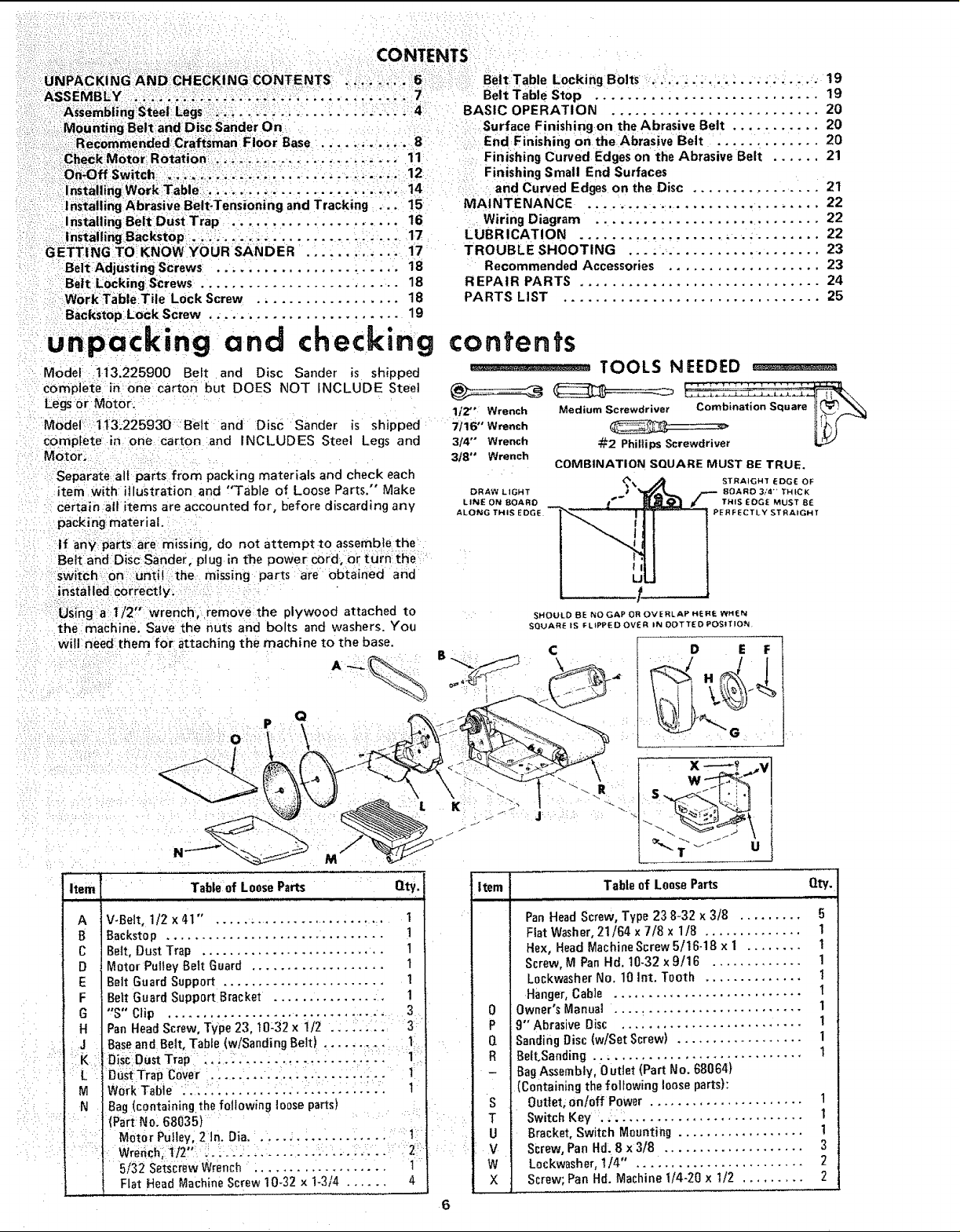
unpacking and checking
Model 113.225900 Belt and Disc Sander is shipped
complete inone carton but DOES NOT INCLUDE Steel
Legs or M0tor.
Model: t13i225930 Belt and Disc Sander is shipped
complete in one carton and INCLUDES Steel Legs and
Motor,
Separate aif parts from packing materials and check each
item With illustration and 'q'able of Loose Parts," Make
certain all items are accounted for, before discarding any
pack ing material.
If any parts are missing, do not attempt to assemble the
Belt and Disc Sander, plug in t'he power cord, or turn: the
switch on until the missing parts are obtained and
installed correctly.
using a t/2, wrench, remove the plywood attached to
the machine, Save the nuts and bolts and washers. You
will need them for attaching the machine to the base. C
A-_ B ,,,_,,_ \_
contents
1/2" Wrench
7116" Wrench
3/4" Wrench
318" Wrench
DRAW LIGHT
LINE ON BOARD
ALONG THIS EDG
TOOLS NEEDED _ ....
_/_2Phillips Screwdriver
COMBINATION SQUARE MUST BE TRUE.
% STRAIGHT EDGE OF
• ROARD 3/4 '_ THICK
I '_ THIS EOGE MUST 8E
PERFECTLY STRAIGHT
D E F
_-:t 2 • "-..
Item Table of Loose Parts Qty.
V-Belt, 1/2 x 41" , ......................... 1
Backstop ............................... 1
Beff, Dust Trap .......................... 1
Motor Putley Belt Guard ................... t
Belt Guard Support ....................... 1
Bert Guard Support Bracket ................ 1
"S" Clip ............................... . 3
Pan Head Screw, Type 23, t0:32 x 1/2 .: : :.;:.: :3
Base and Belt, Table (w/Sanding Belt). ..... :....... :11:
OisCOustTrap: :'::-::-'-i-:,: :-- .... :':::::
:DuSt Trap C0:ve:r . : .... ... .... ; :. .... : ..... I:
Bag (c0ntainingthe following loose parts) :
(Part No: 68035)
MotOr Pulley, 2In. Dia. _.... :.... .... : ..... i1
5/32 Se_crewWrench :.................. 1
Flat Head Machine Screw 10-32 x 1-3/4 ...... 4
Item Table of Loose Parts Qty.
- Bag Assembly, 0 utlet (Part No. 68064}
S Outlet, on/0ff Power ...................... 1
T Switch Key . .. .......................... 1
V Screw, Pan Hd, 8 x 3/8 .................... 3
W Lockwasher, 1/4" 2
ii , i, i
Pan Head Screw, Type 23 8-32 x 3/8 ......... 5
Fiat Washer, 21/64 x 7/8 x 1/8 .............. 1
Hex, Head Machine Screw 5/16-18 x I ........ 1
Screw, M Pan Hd. 10-32x 9/16 ............. 1
L0ckwasher No. 10 Int. Tooth .............. 1
Hanger, Cable ........................... t
0 Owner's Manual ........................... 1
P 9" Abrasive Disc ..........................
Q Sanding Disc (w/Set Screw) .................. 1
R Belt,Sanding .............................. 1
(containing the following loose parts):
U Bracket, Switch Mounting .................. !
X Screw; Pan Hd. Machine 1/4-20 x 1/2 ......... 2
6
1
assembly ;........
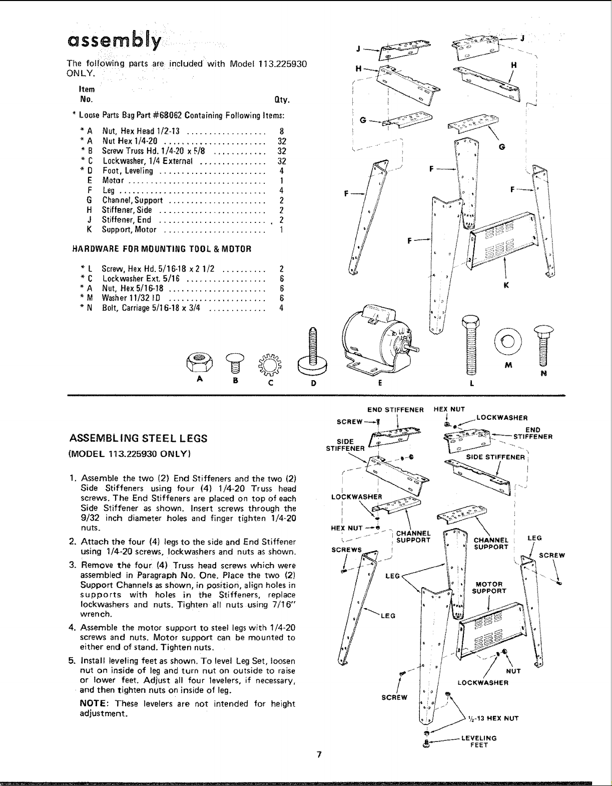
The following parts are included with Model 1t3.225930
ONLY. . :
Item
No. O.ty.
* LoosePartsBagPart-#68062 Containing FollowingItems:
* A Nut, Hex Head 1/2-t3 .................. 8
* A Nut Hex 1/4-20 ....................... 32
* B ScrewTrussHd. 1/4-20 xF/8 ............ 32
* C L0ckwasher,1/4 External ............... 32
* D Foot, Leveling ........................ 4
E Motor ............................... 1
F Leg ................................. 4
G Channel,Support ...................... 2
H Stiffener, Side ........................ 2
J Stiffener, End ........................ , 2
K Support, Motor ....................... 1
HARDWARE FORMOUNTING TOOL & MOTOR
* L Screw, Hex Hd. 5/16-18 x 2 1/2 .......... 2
* C Lockwasher Ext. 5/16 ................... 6
*A Nut, HexS/tG-18 ...................... 6
* M Washer11/321D ...................... 6
* N B01t,Carriage5/16-18 x 3/4 ............. 4
H
G
©
A B C
ASSEMBLING STEEL LEGS
(MODEL 113.225930 ONLY)
1,
Assemble the two (2) End Stiffeners and the two (2)
Side Stiffeners using four (4) 1/4-20 Truss head
screws. The End Stiffeners are placed on top of each
Side Stiffener as shown, insert screws through the
9/32 inch diameter holes and finger tighten 1/4-20
nuts.
.
Attach the four (4) legs to the side and End Stiffener
using 1/4-20 screws, IockwasherS and nuts as shown.
3.
Remove the four (4) Truss head screws which were
assembled in Paragraph No. One. Place the two (2)
Support Channels as shown, in position, align holes in
supports with holes in the Stiffeners, replace
!ockwashers and nuts. Tighten all nuts using 7/16"
wren ch.
4_
Assemble the motor support to steel legs with 1/4-20
screws and nuts. Motor support can be mounted to
either end of stand. Tighten nuts,
5.
Install leveling feet as shown. To level Leg Set, loosen
nut on inside of leg and turn nut on outside to raise
or lower feet. Adjust all four levelers, if necessary,
and then tighten nuts on inside of leg.
NOTE: These levelers are not intended for height
adjustment.
M
D
END STIFFENER
HEX NUT
l _,.,. LOCKWASHER
SIDE STIFFENER i
CHANNEL
SUPPORT
END
i
o
LEG
SCREW
\
MOTOR
SUPPORT _
1
SCREW
7
bly
_ 2
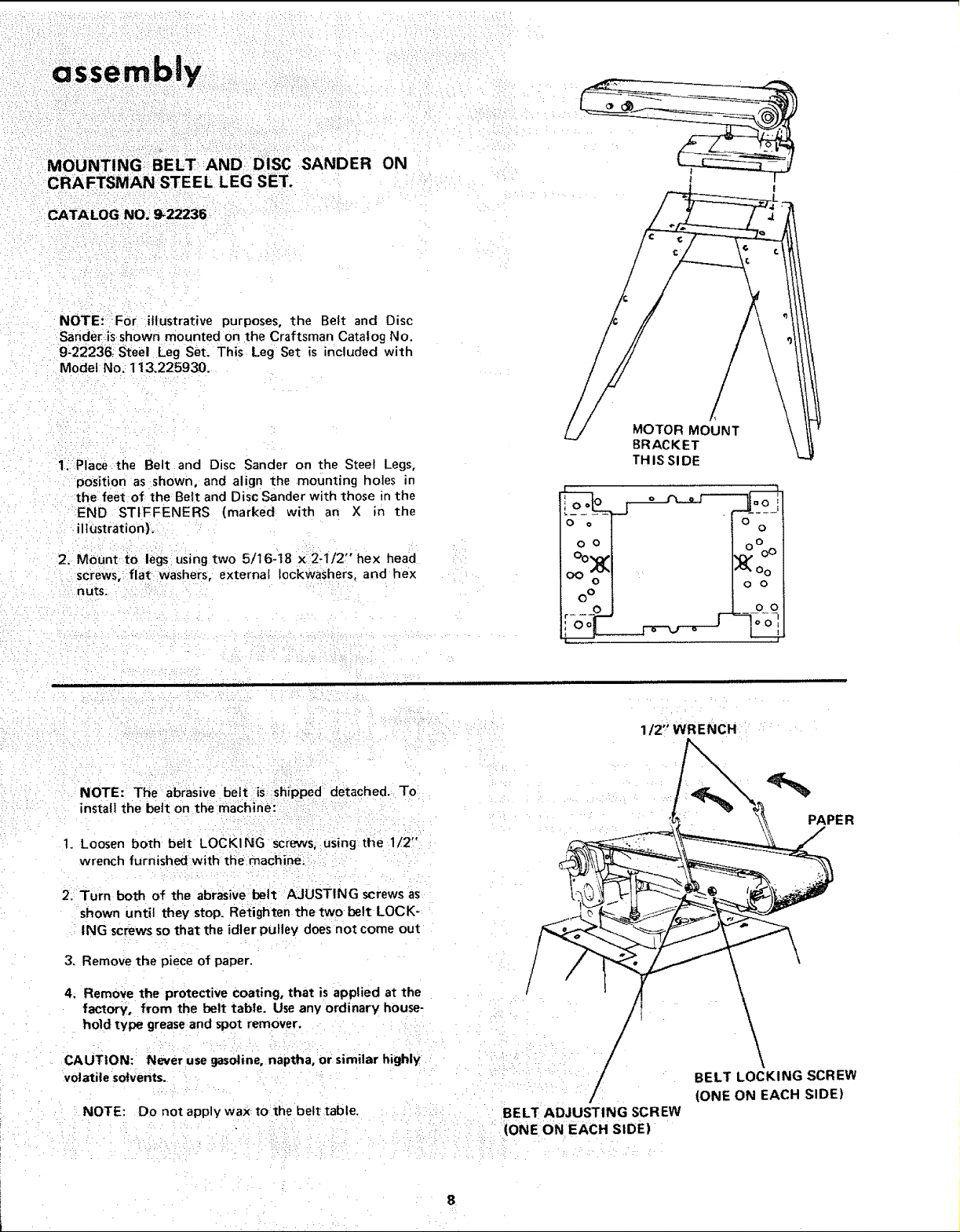
MOUNTING BELT AND DiSC SANDER ON
CRAFTSMAN STEEL LEG SET.
CATALOG NO,_ _22236-
NOTE!: =FOr illustrative purposes, the Belt and Disc
Sander=isshown mounted on the Craftsman Catalog No.
9-22236; Steel Leg set. This Leg Set is included with
Model No. 113.225930.
1_ Place the Belt and Disc Sander on the Steel Legs,
position as shown, and align the mounting holes in
the feet of the Belt and Disc Sander with those in the
END STIFFENERS (marked with an X in the
ilhJstration}.
/
MOTOR MOUNT
BRACKET
TH IS SI DE
2, MOunt to legs using two 5/I6-t8 x 2-1/2" hex head
screws, flat washerS, external fockwaShers, and hex
nuts.
NOTE: The abrasive belt is shipped detached. To
install the belt on the machine:
t. Loosen both belt LOCKING screws, using the 1/2"
wrench furnished with tt_e machine;
2. Turn both of the abrasive belt AJUSTING screws as
shown until they stop. Retighten the two belt LOCK-
ING screws so that the idler pulley does not come out
3. Remove the piece of paper.
4. Remove the protective coating, that is applied at the
factory, from the belt tabte. Useany ordinary house-
hold type grease and spot remover.
1/2" WRENCH
PAPE R
CAUTION: Never use gasoline, naptha, or similar highly
volatile solvents.
NOTE: Do not apply wax tothe belt table.
BELT ADJUSTI NG SCREW
/
(ONE ON EACH SIDE)
BELT LOCKING SCREW
(ONE ON EACH SIDE)
assembly
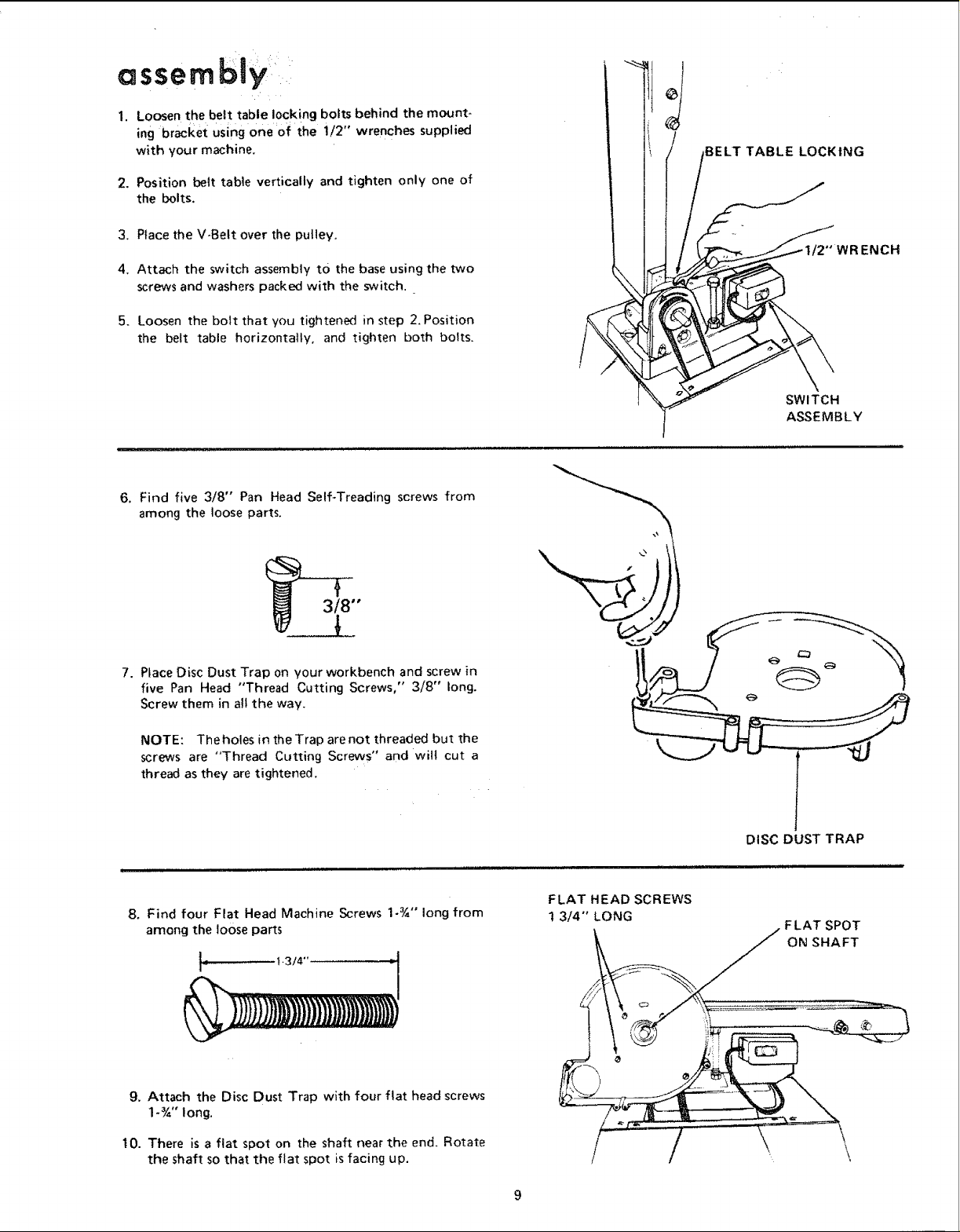
I. Loosen the belt table locking bolts behind the mount-
ing bracket using one of the i12" wrenches supplied
with your machine,
2, Position belt table vertically and tighten only one of
the bolts.
JBELT TABLE LOCKING
3. Place the V-Bett over the pulley,
4. Attach the switch assembly tO the base using the two
screws and washers packed with the switch.
5. Loosen the bolt that you tightened in step 2. Position
the belt table horizontally, and tighten both bolts.
6. Find five 3/8" Pan Head Self-Treading screws from
among the loose parts,
3/8"
7. Place Disc Dust Trap on your workbench and screw in
five Pan Head "Thread Cutting Screws," 3/8" long.
Screw them in all the way,
!NCH
SWITCH
ASSEMBLY
NOTE: The holes in the Trap are not threaded but the
screws are "Thread Cutting Screws" and wilt cut a
thread as they are tightened.
B. Find four Flat Head Machine Screws 1-¾" long from
among the loose parts
! _ t.3/4'
9, Attach the Disc Dust Trap with four flat head screws
1-¾" long.
10. There is a flat spot on the shaft near the end, Rotate
the shaft so that the flat spot is facing up.
FLAT HEAD SCREWS
t 3/4" LONG
DISC DUST TRAP
FLAT SPOT
ON SHAFT
 Loading...