

Craftsman 11322521 Owner’s Manual

ISearsl
Serial
Number
Model and serial
number may be found
at the right-hand side
of the base.
You should record both
model and serial number
in a safe place for
future use. ,,
BE£ T AND DISC SANDER
Read GENERAL and
ADDITIONAL SAFETY
INSTRUCTIONS
carefully
Sold by SEARS, ROEBUCK AND CO., Chicago, IL. 60684 U.S.A.
Part No 68034 Printed InUSA
o assembly
® operating
® repair parts

FULL ONE YEAR WARRANTY ON CRAFTSMAN BELT AND DISC SANDER
If within one year from the date of purchase, this Craftsman Belt and Disc Sander fails due to a defect in
material or workmanship. Sears will repair it free of charge
Warranty service is available by simply contacting the nearest Sears store or Service Center throughout the
United States
This warranty gives you specific legat rights, and you may also have other rights which vary from state to state
SEARS_ ROEBUCK ANDCO
RSC 41-3
SEARS TOWER
CHICAGO IL 60684
generaB safely insfrucfions for power fooUs
1 KNOW YOUR POWER TOOL
Read the owner's manual carefully Learn its application
and limitations as well as the specific potential hazards
peculiar to this tool
2, GROUND ALL TOOLS
This tool is equipped with an approved 3-conductor
cord and a 3-plong grounding type plug to fit the proper
grounding type receptacle Th_ green conductor in the
cord is the grounding wire Never connect the green wire
to a live terminal
3 KEEP GUARDS IN PLACE
- Jn working order and in proper adjustment and align
merit
4 REMOVE ADJUSTING KEYS AND WRENCHES
Form habit of checking to see that keys and adjusting
w_enches are removed from tool before turning it on
5 KEEP WORK AREA CLEAN
Cluttered areas and benches mvite accidents Ftoor
must not be slippery due to wax or sawdust
6. AVOID DANGEROUS ENVIRONMENT
Don't use power tools in damp or wet locations or ex
pose them to rain Keep work area well lighted Provide
adequate surrounding work space
7 KEEP CHILDREN AWAY
Atl visitors should be kept a safe distance from work area
8. MAKE WORKSHOP KID-PROOF
- with padlocks, master switches, or by removing starter
keys
9. DON'T FORCE TOOL
It will do [he job better and safer at the rate for which
il was designed
10 USE RIGHT TOOL
Don't force tool or attachment to do a job it was not
designed for
11 WEAR PROPER APPAREL
Do not wear _oose clothing, gloves neckties or jewelry
(rings, wristwatches) to get caught m moving parts
NONSLIP footwear ts recommended Wear protective
had covering to contain tong hair Roll tong sleeves
above the elbow
12 USE SAFETY GOGGLES (Head Protection)
Wear safety goggles (must comply w_th ANS Z87 1)
at all times Also use face or dust mask if cutting opm
at_on is dusty and ear protectors (plugs or muffs) during
extended periods Of operatlon
13_ SECURE WORK
Use clamps or a vise to hold work when practical Its
safer than using your hand frees both hands to operate
tool
14_ DON'T OVERREACH
Keep proper footing and balance at alt ttmes
15. MAINTAIN TOOLS WITH CARE
Keep tools sharp and clean for best and safest perform
ance Follow instructions for lubricating and changing
accessories
16. DISCONNECT TOOLS
before serv*cmg; when changing accessories such as
blades bits cutters etc
17, AVOID ACCIDENTAL STARTING
Make sure switch is in "OFF" position before plugging
in
18. USE RECOMMENDED ACCESSORIES
Consult theowners manual for recommended accessories
Follow the instructions that accompany the accessories
The use of improper accessories may cause hazards
19, NEVER STAND ON TOOL
Serious iniury could occur if the tool is tipped or if the
cutting tool is accidentally contacted
Do not store materials above or near the tool such that
it is necessary to stand on the tool to reach them
20. CHECK DAMAGED PARTS
Before further use of the tool a guard or other part that
is damaged should be carefully checked to ensure that it
will operate properly and perform its intended func1_ion
Check for alignment of moving parts binding of moving
parts, breakage of parts, mounting_ and any other con.
ditions that may affect its operation A guard or other
part that is damaged should be properly repaired or
reptaced
21 DIRECTION OF FEED
Feed work into a blade or cutter against the direction of
_otation of the blade or cutter only
22.
NEVER LEAVETOOLRUNNING
UNATTENDED
Turn power off Don[ leave toot until it comes to a
complete stop
2

additional safe,/instructions for
beUt and disc sander
Safety is a combination of operator common sense and
alertness at all times when the finishing machine is being
used,
WARNING: FOR YOUR OWN SAFETY, NO NOT
ATTEMPT TO OPERATE YOUR FINISHING
MACftlNE UNTIL IT IS COMPLETELY ASSEM-
BLED AND INSTALLED ACCORDING TO THE
INSTRUCTIONS . . . AND UNTIL YOU HAVE
READ AND UNDERSTOOD THE FOLLOWING.
PAGE
1, General Safety Instructions For Power Tools .... 2
2. Getting To Know Your Sander ................. 18
3 Basic Machine Operation .......................... 21
4. Maintenance ............................ 23
5.. Stability Of Machine
If there is any tendency for the machine to tip over or
move during certain operations such as when finishing
long heavy boards, the sander should be bolted down
6 Location
The machine should be positioned so neither the opera-
tor nor a casual observer is forced to stand in line with
the abrasive belt or disc This machine is intended for
indoor use only
f Make sure the abrasive belt runs in the right direction
Always have the tracking adjusted correctly so that the
belt does not run off the pulleys
g. Hold the work firmly when finishing on the abrasive
belt and against the worktable when finishing on the
disc
h Always adjust the worktable to within 1/16 in of the
abrasive disc or belt
When finishing a large piece of material, make sure it
is supported at table height,
Never leave the machine work area with the power on,
before the machine has come to a complete stop, or
without removing and storing the switch key
k Never operate the machine with protective cover on
the unused shaft end of the motor removed
9. If any part of this belt disc sander should break, bend,
or fail in any way or any electrical component fail to
perform properly, or if any is missing, shut off power
switch, remove power supply cord from power supply
and replace damaged missing and/or failed paris before
resuming operation
10 Read and follow the instructions appearing on label on
the rear of the Disc Dust Trap (Disc Housing):
7. Kickback
When finishing on the Disc, always apply the workpiece
to the "Down Side" of the disc, Applying the work-
piece to the "Up Side" could cause it to fly up
(kickback) which could be hazardous
8 Protection: Eyes, Hands, Face, Ears, Body
a Wear safety goggles that comply with ANSZ87 1-
1968, and a face shield if operation is dusty Wear
ear plugs or muffs during extended periods of opera-
tion
b, Do not finish pieces of material too small to hold by
hand
c, Avoid awkward hand positions, where a sudden slip
could cause a hand to move into the abrasive disc or
belt
d. Never climb on the machine
e. Never turn your Sander "ON" before clearing the
table(s) or work surface(s) of all objects (tools,
scraps of wood, etc) except for the workpiece and
related feed or support devices for the operation
planned
DANGER
FOR YOUR OWN SAFETY:
1. READ AND UNDERSTAND OWNERS MAN-
UAL BEFORE OPERATING MACHINE
2 WEAR SAFETY GOGGLES AND DUST MASK
3_KNOW HOW TO AVOID "KICKBACKS*" ON
SANDING DISC
4 ALWAYS SUPPORT WORKPIECE WITH "BACK
STOP" OR "WORKTABLE"
11 Think Safety.
CAUTION: This machine is not designed for heavy
deburring operations. When finishing ferrous met-
als, sparks will be generated and could cause a
fire. Disconnect any type of dust collecting hose
from the machine. Also remove all traces of wood
dust that may have accumulated inside the dust
traps in the machine.
3
additiona8 safe instructions
for beat and disc sander
WARNING: THE 2-1/2" MACHINE PULLEY AND
THE 2" MOTOR PULLEY FURNISHED, WILL
RUN THE DISC AT APPROXIMATELY 2700
RPM AND THE BELT AT APPROXIMATELY
2100 (FEET PER MINUTE) WHEN USED WITH A
3450 RPM MOTOR. NEVER SUBSTITUTE OR
INTERCHANGE THESE PULLEYS TO INCREASE
THIS SPEED BECAUSE IT COULD BE DANGER-
OUS.
WEAR YOUR
The operation of any power tool can result in foreign
objects being thrown into the eyes, which can result in
severe eye damage. Always wear safety goggles complying
with ANSI Z87.1 (shown on Package) before commencing
power tool operation. Safety Goggles are available at Sears
retail or catalog stores.
WARNING: DO NOT ALLOW FAMILIARITY
(GAINED FROM FREQUENT USE OF YOUR
MACHINE) TO BECOME COMMONPLACE. AL-
WAYS REMEMBER THAT A CARELESS FRAC-
TION OF A SECOND IS SUFFICIENT TO IN-
FLICT SEVERE INJURY.
4
motor specifications and enectricaUrequirements
This machine is designed to use a 3450 RPM motor only
Do not use any motor that runs faster than 3450 RPM
It is wired for operation on 110-120 volts, 60 Hz,, alter-
nating current IT MUST NOT BE CONVERTED TO
OPERATE ON 230 VOLTS EVEN THOUGH SOME OF
THE RECOMMENDED MOTORS ARE DUAL VOLTAGE
THESE CRAFTSMAN MOTORS HAVE BEEN
FOUND TO BE ACCEPTABLE FOR USE ON
THIS TOOL.
HP RPM VOLTS CATALOG NO.
1/2 3450 110-120 1216
1/2 3450 110-120 1218
3/4 3450 110-120 1219
3/4 3450 110-120 1226
CAUTION: Do not use blower or washing machine motors
or any motor with an automatic reset overload protector
as their use may be hazardous.
CONNECTING TO POWER SOURCE OUTLET
This machine must be grounded while in use to protect
the operator from electric sbock,
Plug power cord into a 110-120V properly grounded type
outlet protected by a 15-amp. time delay or Circuit-Saver
fuse or circuit breaker
If you are not sure that your outlet is properly grounded,
have it checked by a qualified electrician
WARNING: DO NOT PERMIT FINGERS TO TOUCH THE
TERMINALS OF PLUGS WHEN INSTALLING OR RE-
MOVING THE PLUG TO OR FROM THE OUTLET
This power too! is equipped with a 3-conductor cord and
grounding type plug which has a grounding prong, approved
by Underwriters' Laboratories and the Canadian Standards
Association The ground conductor has a green iacket and
is attached to the tool housing at one end and to the ground
prong in the attachment plug at the other end
This plug requires a mating 3-conductor grounded type
outlet as shown
If the outlet you are planning to use for this power tool is
of the two prong type DO NOT REMOVE OR ALTER
THE GROUNDING PRONG iN ANY MANNER Use an
adapter as shown and always connect the grounding lug to
known ground
It is recommended that you have a qualified electrician
replace the TWO prong outlet with a properly grounded
THREE prong outlet
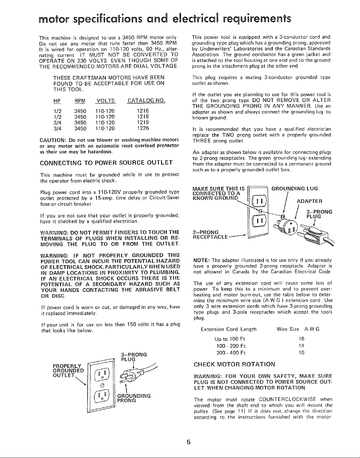
An adapter as shown below is available for connecting plugs
to 2-prong receptacles The green grounding lug_ extending
from the adapter must be connected to a permanent gTound
such as to a properly grounded outlet box
MAKESURETHISIS
GROUNDING LUG
CONNECTED TO A
KNOWN GROUND
ADAPTER
3-PRONG
PLUG
l
2--PRONG
RECEPTACLE---'---_
WARNING: IF NOT PROPERLY GROUNDED THIS
POWER TOOL CAN INCUR THE POTENTIAL HAZARD
OF ELECTRICAL SHOCK,. PARTICULAR LY WHEN USED
IN DAMP LOCATIONS IN PROXIMITY TO PLUMBING.
IF AN ELECTRICAL SHOCK OCCURS THERE IS THE
POTENTIAL OF A SECONDARY HAZARD SUCH AS
YOUR HANDS CONTACTING THE ABRASIVE BELT
OR DISC.
if power cord is worn or cut, or damaged in any way, have
it replaced immediately.
If your unit is for use on less than 150 volts it has a plug
that looks like below
3-PRONG
PLUG
PROPERLY
GROUNDED
/n u)
OUTLETs.
©
/n U]
GROUNDING
PRONG
NOTE: The adapter illustrated is for use only if you aheady
have a properly grounded 2-prong receptacle Adapter is
not allowed in Canada by the Canadian Electrical Code
The use of any extension cord will cause some loss of
power To keep this to a minimum and to prevent over-
heating and motor burn-out, use the table below to deter
mine the minimum wire size (AWG) extension cord Use
only 3 wire extension cords which have 3-prong grounding
type plugs and 3-pole receptacles which accept the tools
plug
Extension Cord Length Wire Size AW G
Up to 100 Ft 16
100_200 Ft 14
200_400 Ft 10
CHECK MOTOR ROTATION
WARNING: FOR YOUR OWN SAFETY, MAKE SURE
PLUG IS NOT CONNECTED TO POWER SOURCE OUT*
LET, WHEN CHANGING MOTOR ROTATION
The motor must rotate COUNTERCLOCKWISE when
viewed from the shaft end to which you wil! mount the
pulley (See page 11) If it does not, change the direction
according to the instructions furnished with the motor
5
unpacking
and checking contents
CONTENTS
UNPACKING AND CHECKING CONTENTS ..... 6
ASSEMBLY .................................... 7
Mounting Belt and Disc Sander On
Recommended Craftsman Floor Base ........ 7
Check Motor Rotation .......................... 11
On-Off Switch .............................. 13
Installing Work Table ....................... 15
Installing Abrasive Belt-Tensioning and Tracking 16
Installing Belt Dust Trap ..................... 17
Installing Backstop .............................. 18
GETTING TO KNOW YOUR SANDER ............ 18
Belt Adjusting Screws .......................... 19
Belt Locking Screws ......................... 19
Work Table Tilt Lock Screw .................... 19
Backstop Lock Screw ............................ 20
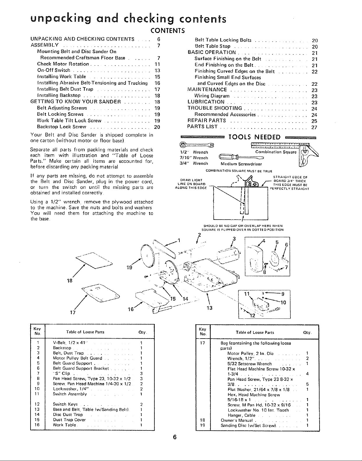
Your Belt and Disc Sander is shipped complete in
one carton (without motor or floor base)
Separate all parts from packing materials and check
each item with illustration and "Table of Loose
Parts." Make certain all items are accounted for,
before discarding any packing material
If any parts are missing, do not attempt to assemble
the Belt and Disc Sander, plug in time power cord,
or turn the switch on until the missing parts are
obtained and installed correctly
Using a 1/2" wrench• remove the plywood attached
to time machine Save the nuts and bolts and washers
You will need them for attaching the machine to
the base
Belt Table Locldng Bolts ....................... 20
Belt Table Stop ......................... 20
BASIC OPERATION ............................. 21
Surface Finishing on the Belt ................. 21
End Finishing on the Belt ................ 21
Finishing Curved Edges on the Belt .............. 22
Finishing Small End Surfaces
and Curved Edges on the Disc ............. 22
MAINTENANCE ......................... 23
Wiring Diagram ...................... 23
LUBRICATION ....................... 23
TROUBLE SHOOTING ............................ 24
Recommended Accessories ................. 24
REPAIR PARTS ................................. 25
PARTS LIST ..................................... 27
°_ _"_°_--° TOOLS NEEDED ==========
1/2"" Wrench __
W16"' Wrench
3/4' Wrench Medium Screwdriver
COMBINATION SQUARE MUST BE TRUE
DRAW LIGHT
LINE ON BOARD
ALONG THI
SHOULD BE NO GAP OR OVERLAP HERE WHEN
SQUARE IS FLIPPED OVER IN DOTTED POSITION
2
"r/ .. 3 5
STRAIGHT EDGE OF
BOARD 3/4" TH{CK
TH_S EDGE MUST BE
PERFECTLY STRAIGHT
Key
No
10
11
12
13
14
15
16
18
17
Table o1 Loose Parts Oty
1
V-Beh 1/2x4!
2
Backstol: 1
3
Belt, Dust Trap . 1
4
Motor Pul ev Belt Guard ]
5
Belt Guard Suoport .
6
3elt Guard SUDDOrt Bracket
7
'S" Clip . 3
8
Pan Head Screw. Type 23. 10-32 x 1/2 3
9
Screw Pan Head Machine 1/4-20 x 1/2 2
LockwasheL 1/4- 2
Switch Assembly i
Switch Keys 2
Baseand Belt Table (w/Sanding Belt) I
Disc Dust TraD I
Dust Trap Cover l
Work Table I
19
14 Z ""-,
16/' " .......
\ ......111 1
L 2"'_
Key
No
17
i
i
i IB
Table of Loose Farts Qty
Bag (containing the following loose
parts)
Motor Pulley, 2 In Din ........ 1
Wrench, 1I2" ............. 2
5/32 Setscrew Wrench ......... 1
Flat Head Machine Screw 10-32 x
1-3/4 ................. 4
Pan Head Screw, Type 23 8-32 x
3/8 ............... 5
Flat Washer 21/64 x 7/8 x 1/8 1
Hex. Head Machine Screw
5/16-18 x 1 ........... 1
Screw MPan Hd. 10-32x9/16 1
Lockwasher No 10 I nt Tooth 1
Hange{, Cable ........ 1
Owner's Manual ............ 1
Sanding Disc (w/Set Screw) ........ 1
6
assembly
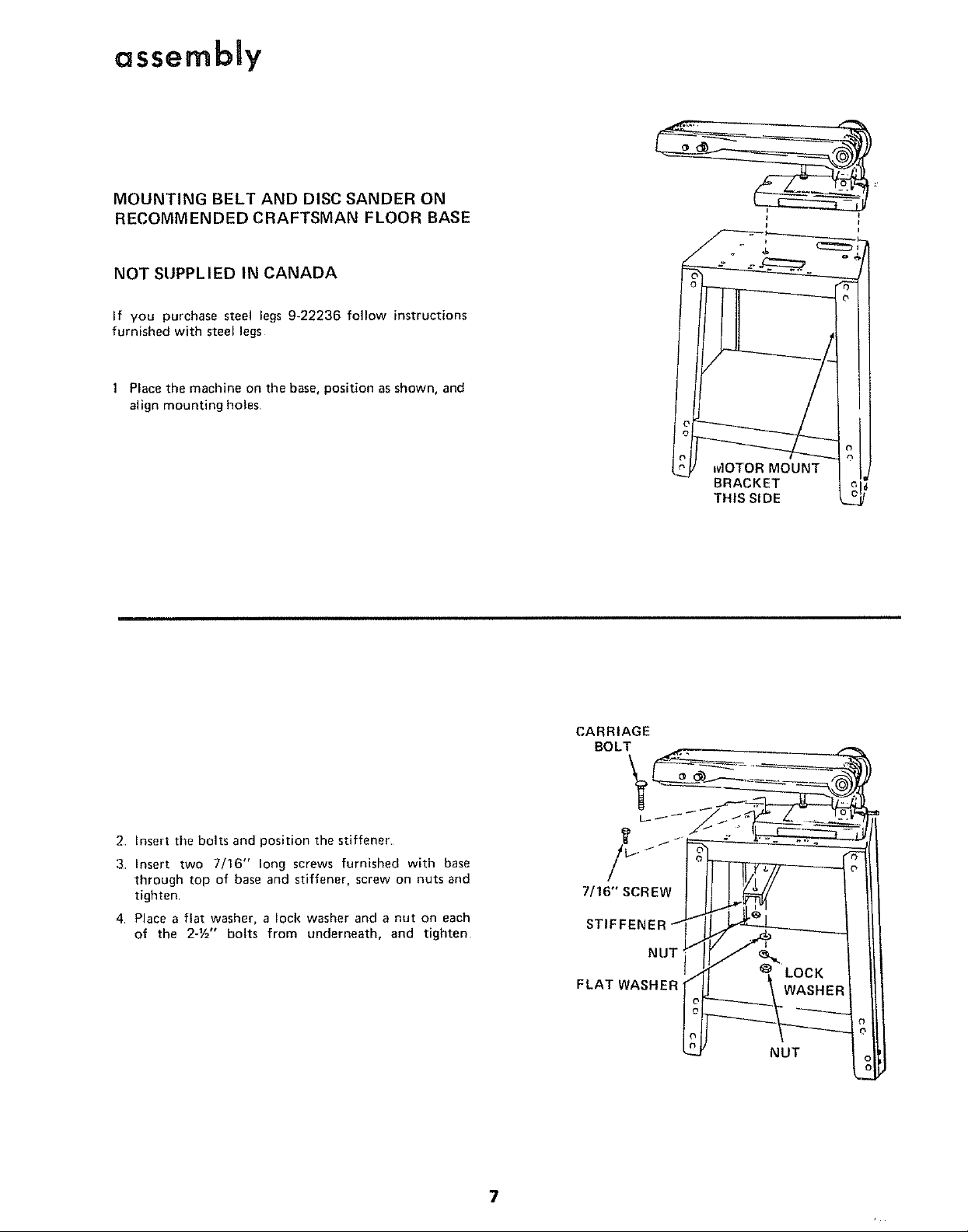
MOUNTING BELT AND DISC SANDER ON
RECOMMENDED CRAFTSMAN FLOOR BASE
NOT SUPPLIED IN CANADA
If you purchase steel legs 9-22236 follow instructions
furnished with steel legs
Place the machine on the base, position as shown, and
align mounting holes
+
t_J MOTOR MOUNT J
BRACKET L
THIS SIDE L__
2 Insert the bolts and position the stiffener
3 Insert two 7/16" long screws furnished with base
through top of base and stiffener, screw on nuts and
tighten
4 Place a flat washer, a lock washer and a nut on each
of the 2-1/='' bolts from underneath, and tighten
CARRIAGE
BOLT
7/16" SCREW
STIFFENEF
NUT
FLAT WASHER
LOCK
WASHER
NUT
7

assembly
NOTE: The abrasive belt is installed on the machine
at the factory so that it does not become damaged
during shipment
Loosen both belt LOCKING screws, using the 1/2"
wrench furnished with the machine
2 Turn both of the belt ADJUSTING screws as shown
until they stop Retighten the two belt LOCKING
screws so that the idler pulley does not come out
3 Slip the belt off and _emove the piece of paper
4. Remove tile protective coating, that is applied at the
factory, from the belt table. Use any ordinary house-
hold type greaseand spot remover.
CAUTION: Never use gasoline, naptha, or similar highly
volatile solvents.
NOTE: Do not apply wax to the belt table
1/2" WRENCH
PAPER
BELT LOCKING SCREW
(ONE ON EACH SIDE)
BELT ADJUSTING SCREW
(ONE ON EACH SIDE)
1 Loosen the belt table locking bolts behind the mount-
ing,bracket using one of the 1/2" wrenches supplied
with your machine,
2. Position belt table vertically and tighten only one of
the bolts
3 Place tile V-Belt over the pulley
4 Attach the switch assembly to the base using the two
screws and washers packed with the switch
5 Loosen the bolt that you tightened in step 2 Position
the belt table horizontally, and tighten both bolts
BELT TABLE LOCKING
-" _ RENCH
SWITCH
ASSEMBLY
8
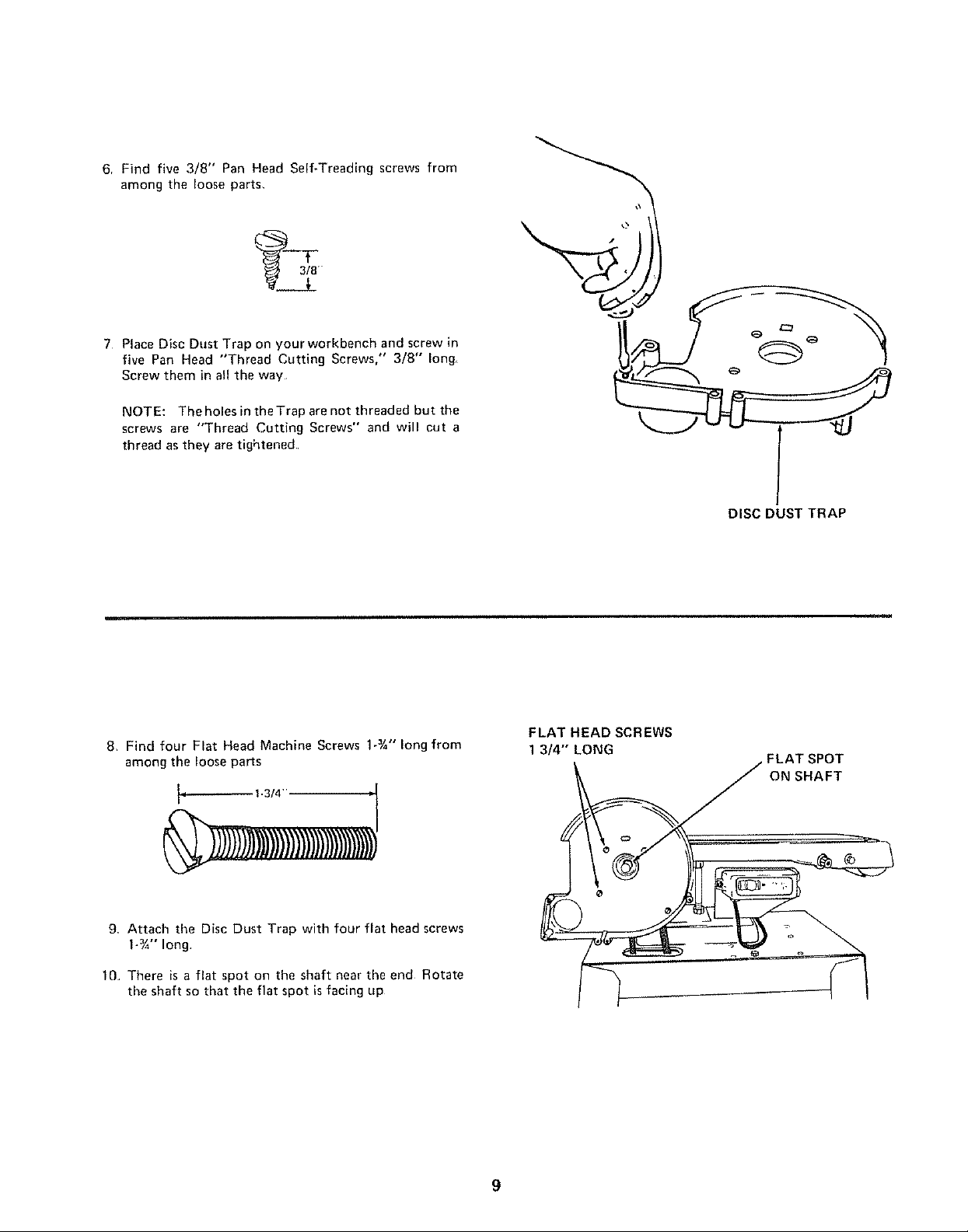
6, Find five 3/8" Pan Head Self-Treading screws from
among the loose parts,
7 Place Disc Dust Trap on yourworkbench and screw in
five Pan Head "Thread Cutting Screws," 3/8" long
Screw them in all the way
NOTE: The holes in the Trap are not threaded but the
screws are "Thread Cutting Screws" and will cut a
thread as they are tightened
DISC DUST TRAP
8, Find four Flat Head Machine Screws 1-3/4"long from
among the loose paris
1-3/4"
9 Attach the Disc Dust Trap with four flat head screws
1-¾" long
10 There is a flat spot on the shaft near the end Rotate
the shaft so that the flat spot is facing up
FLAT HEAD SCREWS
1 3/4" LONG
FLAT SPOT
ON SHAFT
9
 Loading...