

Craftsman 113213843 Owner’s Manual

SAVE THiS MANUAL
FOR FUTURE REFERENCE
MODEL NO.
113.213843
DRILL PRESS WITH
1/3 HP MOTOR
Serial
Number ..........................................
Model and serial number
may be found at the rear of
the head,
You should record both
model and serial number in
a safe place for future use.
CAUTION:
Read GENERAL
and ADDITIONAL
SAFETY
INSTRUCTIONS
carefully
MOTORIZED
13 iNCH
FLOOR MODEL
• assembly
• operating
® repair parts
®
.L PRESS
Sold by SEARS, ROEBUCK AND CO., Chicago, IL. 60684 U.S.A.
PART NO 3P4963 PRINTED iN U.S.A

FULL ONE YEAR WARRANTY ON CRAFTSMAN DRILL PRESS
If within one year from the date of purchase, this Craftsman Drill Press fails due to a defect
in material or workmanship, Sears will repair it, free of charge.
WARRANTY SERVICE IS AVAILABLE BY SIMPLY CONTACTING THE NEAREST SEARS
SERVICE CENTER/DEPARTMENT THROUGHOUT THE UNITED STATES.
THiS WARRANTY APPLiESONLY WHILE THIS PRODUCT mSiN USE iN THE UNITED STATES,
This warranty gives you specific legal rights, and you may also have other rights which
vary from state to state.
SEARS, ROEBUCK AND CO., Dept. 698/731 A, Sears Tower, Chicago, IL 60684
general safety instructions for power tools
1. KNOW YOUR POWER TOOL 12.
Read and understand the owner's manual and
labels affixed to the tool. Learn its application and
limitations as well as the specific potential hazards
peculiar to this tool.
2. GROUND ALL TOOLS
This toolisequipped with an approved 3-conductor
cord and a 3-prong grounding type plug to fit the 13.
proper grounding type receptacle. The green con-
ductor in the cord is the grounding wire. Never
connect the green wire to a live terminal.
3. KEEP GUARDS iN PLACE
In working order, and in proper adjustment and
alignment.
4. REMOVE ADJUSTING KEYS AND
WRENCHES
Form a habit of checking to see that keys and
adjusting wrenches are removed from tool before
turning it on.
5. KEEP WORK AREA CLEAN
Cluttered areas and benches invite accidents.
Floormustnotbe sl_pperydue towax orsawdust. 17.
6. AVOID DANGEROUS ENVIRONMENT
Don't use power tools in damp or wet locations or
expose them to rain. Keep work area well lighted. 18.
Provide adequate surrounding work space.
=
KEEP CHILDREN AWAY
All visitors should be kept a safe distance from
work area.
8, MAKE WORKSHOP KID.PROOF
--with padlocks, master switches, or by removing
starter keys.
9. DON'T FORCE TOOL
It will do the job better and safer at the rate for
which it was designed.
10. USE RIGHT TOOL
Don't force tool or attachment to do a job it was
not designed for.
11. WEAR PROPER APPAREL
Do not wear loose clothing, gloves, neckties or
jewelry (dngs, wristwatches) to get caught inmov-
ingparts. Nonslipfootwear isrecommended. Wear
protective hair covering to contain long hair. Roll
long sleeves above the elbow.
USE SAFETY GOGGLES (He_ Protection)
Wear Safety goggles _must c_mply with ANSI
Z87.1 )at all times. Everyday eyeglasses onlyhave
impact resistant lenses, they are NOT safety glas-
ses. Also. use face or dust mask if cutting operation
is dusty, and ear protectors Iplugs or muffs) during
extende(_ periods of operation.
SECURE WORK
Use clamps or a vise to hold work when practical.
It's safer than using your hand, frees both hands
to operate tool.
14. DON'T OVERREACH
Keep proper footing and balance at all times.
15, MAINTAIN TOOLS WITH CARE
Keep tools sharp and clean for best and safest
performance. Follow instructionsfor lubricatingand
changing accessories,
16. DISCONNECT TOOLS
Before servicing; when changing accessories such
as blades, bits, cutters, etc.
AVOID ACCIDENTAL STARTING
Make sure switch is in"OFF" position before plug-
ging in.
USE RECOMMENDED ACCESSORIES
Consult the owner's manual for recommended ac-
cessories. Follow the instructions that accompany
the accessories. The use of improper accessones
may cause hazards.
19. NEVER STAND ON TOOL
Serious injury could occur if the tool is tipped or if
the cutting tool is accidentally contacted.
Do not store materials above or near the tool such
that it is necessary to stand on the tool to reach
them.
20. CHECK DAMAGED PARTS
Before further use of the tool, a guard orother part
that is damaged should be carefully checked to
ensure that it will operate properly and perform its
intended function. Check for alignment of moving
parts, binding of moving parts, breakage of parts,
mounting, and any other conditions that may affect
its operation. A guard or other part that is damaged
should be property repaired or replaced.

21. DIRECTION OF FEED
Feed work into a blade or cutter against the direc-
tion of rotation of the blade or cutter only.
22. NEVER LEAVE TOOL RUNNING UNATTENDED
Turn power off. Don't leave tool until it comes to a
complete stop.
additional safety instructions for drWmlpresses
WARNING: For your own safety, do not attempt to
operate your drill press untiBit is completely assem-
bled and installed according to the instructions
• , , and until you have read and understand the
following:
Page
1. General Safety instructions for Power Tooms. 2
2. Getting to Know Your Drit! Press ........ 12
3. Basic Drill Press Operation ............. 15
4. Adjustments .......................... 17
5. Maintenance .......................... 18
6. Stability of Drill Press
If there is any tendency of the drill press to tilt or
move during certain operations, the drill press
should be bolted to the floor. An alternate is to
securely bolt a flat piece of 1/2"exterior plywood
large enough to stabilize the drill press to the under-
side of the Base. extending to both sides, and to
rear if desired. Make sure the plywooo won't trip
the operator. Do not use pressed wood panels -
they can break unexpectedly.
If the workpiece _s too large to support with one
hand. provide an auxiliary support.
7. Location
The drill press should be positioned so neither the
operator nor a casual observer is forced to stand
in line with a potential Kickback, in a poorly lit area
or where the surface could cause trips, slips orfalls.
8. Kickback
A kickback occurs when the workpiece is suddenly
thrown in the OPPOSITE direction to the DIREC-
TION OF FEED: THIS CAN CAUSE SERIOUS IN-
JURY. Kickbacks are most commonly caused by
use of accessories NOT listed on page 2!.
9. Protection: Eyes, Hands, Face, Ears and Body
WARNING: To avoid being pulled intothe spin-
ning tool --
1. Do NOT wear:
-- gloves
-- necktie
-- loose clothing
-- jewelry
2. Tie back long hair
a. If any part of your drill press is missing, malfunc-
tioning, has been damaged or broken.., such
as the motor switch, or other operating control,
a safety device or the power cord . . . cease
operating immediately until the particular part is
properly repaired or replaced.
b. Never place your fingers in a position where
they could contact the drill or other cutting tool
if the workpiece should unexpectedly shift or
your hand should slip.
c. To avoid injury from parts thrown by the spring,
follow instructions exactly as given and shown
in adjusting spring tension of quill.
d. To prevent the workpiece from being torn from
your hands, spinning of the tool, shattering the
tool or being thrown, always properly support
your work so it won't shift or bind on the tool:
-- Always position BACKUP MATERIAL (use
beneath the workpiece} to contact the left
side of the column.
-- Whenever possible, position the WORK-
PIECE to contact the left side of the column
- if it is too short or the table is tilted, clamp
solidly to the table. Use table slots or clamp-
ing ledge around the outside edge of the
table.
A drill press VICE must always be fastened
to the table.
--Never perform any operation "FREE-.
HAND" (hand-holding workpiece rather
than supporting it on the tabie_ except
when polishing.
-- Securely lock Head and Support to Column
Table Arm to support, and Table to Table
Arm before operating drill press
Never move the Head or Table while _r_e
tool is running
-- Before starting the operation jog the motor
switch to make sure the drill or other cutting
too! does not have excessive runout •¢_Ob..
Die} or cause vibration.
If a workpiece overhangs the table such
that it wil! fall or tip if not held. clamp it to
the table or provide auxiliary support,
-- Use fixtures for unusual operations to
adequately hold, guide and position work-
piece.
-- Use the SPINDLE SPEED recommended
for the specific operation and workpiece
material - check the panel on the left side
of the head for drilling information: for ac-
cessories, refer to the instructions provided
with the accessories.
f. Never climb on the drill press Table. i! could
break or pul! the entire drill press down on you
g, Turn the motor Switch Off and eut away the
Switch Key when leaving the drill press.
h. To avoid injur_ from thrown work or tooi contact.
do NOT perform layout, assembly, or setup work
on the table while the cutting too! is rotating.
10. Use only accessories designed for this driJl
press to avoid serious injury from thrown bro,-
ken parts or work pieces.
a. Holesaws must NEVER be operated on this dri!l
press at a speed greater than 400 RPM.
b. Drum sanders must NEVER be operated on this
drill press at a speed greater than 1800 RPM.
additional safety instructions for drill
presses
c. Do not install or use any drill that exceeds 7"'in
length or extends 6" below the chuck jaws. They
can suddenly bend outward or break.
d. Do not use wire wheels, router bits. shaper cut-
ters, circle (fly) cutters or rotary planers on this
drill press.
11. Note and Follow the Safety Warnings and In-
structions that Appear on the Panel on the Left
Side of the Head:
DANGER ]
FOR YOUR OWN SAFETY:
1. READ AND UNDERSTAND OWNERS MAN-
UAL BEFORE OPERATING MACHINE.
2. WEAR SAFETY GOGGLES.
3. DO NOT WEAR GLOVES, NECKTIE, OR
LOOSE CLOTHING. TiE BACK LONG HAIR.
4. SECURELY CLAMP WORK TO TABLE iF iT
iS TOO SHORT TO CONTACT THE COLUMN
WHEN iN OPERATING POSiTiON
5. USE RECOMMENDED SPEED FOR DRILL,
ACCESSORY, AND WORKPIECE MATER-
IAL.
6. SECURELY LOCK HEAD AND SUPPORTTO
COLUMN, ARM TO SUPPORT, AND TABLE
TO ARM BEFORE OPERATING DRILL
PRESS.
7. USE ONLY RECOMMENDED ACCES-
SORIES.
12. This Drill Press has 5 speeds as listed below:
400 RPM
800 RPM
1200 RPM
1800 RPM
2800 RPM
See right side of Head for specific placement of
belt on pulleys.
13. Think Safety. Safety is a combination of operator
common sense and alertness at all times when the
drill press is being used.
WARNING: Do not allow familiarity (gained from
frequent use of your drill press) to become com-
monplace. Always remember that a careless frac-
tion of a second is sufficient to inflict severe injury.
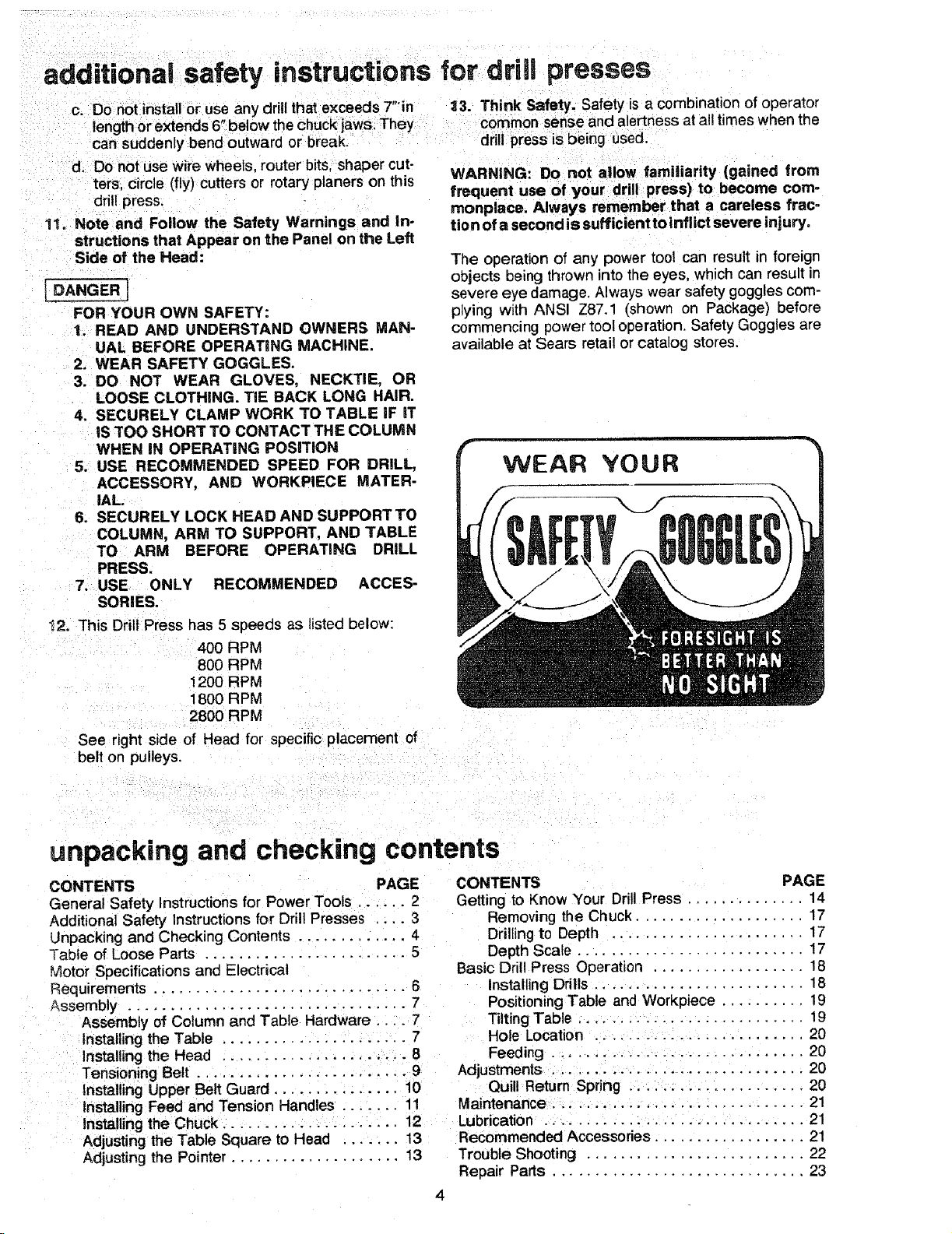
The operation of any power tool can result in foreign
ot_jects being thrown into the eyes, which can result in
severe eye damage. Always wear safety goggles com-
plying with ANSI Z87.1 (shown on Package) oefore
commencing power tool operation. Safety Goggles are
available at Sears retail or catalog stores.
unpacking and checking contents
CONTENTS PAGE
General Safety Instructionsfor Power Tools ...... 2
Additional Safety Instructions for Drill Presses ... 3
Unpacking and Checking Contents ............. 4
Table of Loose Parts ........................ 5
Motor Specifications and Electrical
Requirements .............................. 6
Assembly ................................. 7
Assembly of Column and Table Hardware .... 7
Installing the Table ...................... 7
Installing the Head ..................... 8
Tensioning Belt ........................ 9
Installing Upper Belt Guard ............... 10
Installing Feed and Tension Handles ....... 11
Installingthe Chuck ..................... 12
Adjusting the Table Square to Head ...... 13
Adjusting the Pointer .................... 13
CONTENTS PAGE
Getting to Know Your Drill Press .............. 14
Basic Drill Press Operation .................. 18
Adjustments ............................. 20
Maintenance .............................. 21
Lubricatior ............................... 21
Recommended Accessories .................. 21
Trouble Shooting .......................... 22
Repair Parts .............................. 23
Removing the Chuck .................... 17
Drillingto Depth ...................... 17
Depth Scale ........................... 17
Installing Drills ......................... 18
Positioning Table and Workpiece .......... 19
Tilting Table ........................... 19
Hole Location ......................... 20
Feeding .............................. 20
Quill Return Spring ..................... 20
UNPACKING AND CHECKING
CONTENTS
Model No. 113.213843 is shipped complete in one car-
ton and includes a 1/3 HP 1725 RPM motor.
Separate all parts from packing materials and check
each one with the "Table of Loose Parts" to make certain
all items are accounted for, before discarding any pack-
ing material.
WARNING: For your own safety: If any parts are
missing, do not attempt to assemble the drill press,
plug in the power cord or turn the switch on until
the missing parts are obtained and installed cor-
rectly.
Remove the protective oil that is applied to the table
and column. Use any ordinary household type grease
and spot remover.
WARNING: To avoid fire or toxic reaction, never
use gasoline, naptha or similar highly votatile sol-
vents.
Apply a coat of paste wax to the table to prevent rust.
Wipe all parts thoroughly with a clean dry cloth.
.... TOOLS NEEDED
COMBINA_
COMBINATION SQUARE MUST BE TRUE
DRAW LIGHT STRAIGHT EDGE OF
LINE ON BOARD BOARD 314" THICK
ALONG THIS EDGE_ _ .THIS EDGE MUST BE
_ PERFECTLY STRAIGHT
SHOULD BE NO GAP OR OVERLAP WHEN
SQUARE IS FLIPPED OVER IN DOTTED POSITION
MEDIUM 8.iNCH ADJUSTABLE
SCREWDRIVER WRENCH
1t2 WRENCH
1/8" - 3/16"
HEX "L" WRENCH
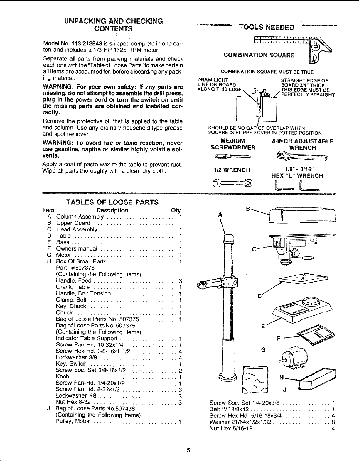
TABLES OF LOOSE PARTS
item Description Qty.
A Column Assembly ...................... 1
B Upper Guard .......................... 1
C Head Assembly ........................ 1
D Table ................................. 1
E Base ................................. 1
F Owners manual ........................ 1
G Motor ................................ 1
H Box Of Small Parts ..................... 1
Part #507376
(Containing the Following Items)
Handle, Feed .......................... 3
Crank, Table .......................... 1
Handle, Belt Tension .................... 1
Clamp, Bolt ........................... 1
Key, Chuck ........................... 1
Chuck ................................ 1
Bag of Loose Parts No. 507375 ........... 1
Bag of Loose Parts No. 507375
(Containing the Following Items)
Indicator Table Support .................. 1
Screw Pan Hd. 10-32xl/4 ................ 1
Screw Hex Hd. 3/8-16xl 1/2 .............. 4
Lockwasher 3/8 ........................ 4
Key, Switch ........................... 1
Screw Soc. Set 3/8-16xl/2 ............... 2
Knob ................................ 1
Screw Pan Hal. 1/4-20xl/2 ............... 1
Screw Pan Hd. 8-32xl/2 ................. 3
Lockwasher #8 ........................ 3
Nut Hex 8-32 .......................... 3
J Bag of Loose Parts No.507438
(Containing the Following Items)
Pulley, Motor .......................... 1
A
F
Screw Soc. Set !/4-20x3/8 ............... 1
Belt "V" 3/8x42 ......................... !
Screw Hex Hal. 5/16-18x3/4 .............. 4
Washer 21/64x1/2x1!32 .................. 8
Nut Hex 5/16-18 ....................... 4
motor specifications and emectricalrequirements
MOTOR SPECiFICATiONS This power to01 is equipped with a 3-conductor cord
ThL_ drill nr_._._ i._ d_.._inn_d to H_. _ 17PR RPM motor and ground ng type plug which has a grounding prong,
-- -"- " ........ °............. _ '- _ _"" Underwriters'
;_n_vr_ nnt ,_,_ _nv mntor that run_ faster than 1725 approved uy
--/-.7 ........... _r v (;I _ , , ,
Laboratories
RPM. It is wired for operation on 1! 0-! 20 volts 60 Hz. d,an Standards Assoclat!on..The.ground conductor has
-. ..... , .... r_." a green Jacket and s anaCnea _ome [oo_ hOUsing a[
dt_/l_c_t tt_l L*UL tt_HL
WARNING: To avoid injury from unexpected start- Blue at
up, do not use blower or washing machine motors
or any motor with an automatic reset overload pro-
tector.
• one end and to the ground prong in the attachment
the other end
This plug requires a mating 3-conductor grounded type
outlet as shown.
If the out et you are panning to use for this power tool
CONNECTING TO POWER SOURCE OUTLET
l-his machine must be grounded while in use to protect
ti_e operator from electric shook.
Plug power cord into a 110-120V properly grounded
type outlet protected by a 15-amp. dual element time
delay or Circuit-Saver fuse or circuit breaker.
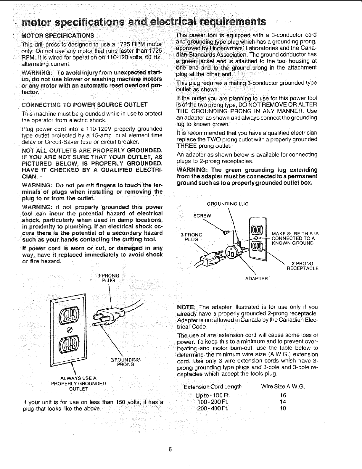
NOT ALL OUTLETS ARE PROPERLY GROUNDED.
_FYOU ARE NOT SURE THAT YOUR OUTLET, AS
PICTURED BELOWo JS PROPERLY GROUNDED,
HAVE IT CHECKED BY A QUALiFiED ELECTRI-
CIAN.
WARNING: Do not permit fingers to touch the ter-
is of the two prong type, DO NOT REMOVE OR ALTER
THE GROUNDIIklG PRONG IN ANY MANNER. Use
an adapter as shown and always connect the grounding
lug to known grown.
It is recommended that you have a qualified electrician
replace the TWO prong outlet with a properly grounded
THREE prong outlet.
An adapter as shown below is available for connecting
plugs to 2-prong receptacles.
WARNING: The green grounding lug extending
from the adapter must be connected to a permanent
ground such as to a properly grounded outlet box.
minals of plugs when installing or removing the
plug toor from the outlet.
WARNING: _f not properly grounded this power
tool can incur the potential hazard of electrical
GROUNDING LUG
SCREW \
shock, particularly when used in damp locations.
in proximity _o plumbing, if an eJectrical shock oc-
curs there is the potential of a secondary hazard
such as your hands contacting the cutting tool.
Ill power cord is worn or cut, or damaged in any
way, have it replaced immediately to avoid shock
or fire hazard.
3-PRONG
PLUG
I
\.
ADAPTER
and the Cana-
RECEPTACLE
GROUNDING cora. Use only 3 wire extension cords which have 3-
PRONG prong grounding type plugs and 3-pole and 3-pole re-
ALWAYS USE A
PROPERLY GROUNDED
OUTLET
if your unit is for use on less than 150 volts, it has a
plug thai looks like the above.
already have a properly grounded 2-prong receptacle.
NOTE: The adapter illustrated is for use only if you
Adapter is not allowed in Canada by the Canadian Elec-
trical Code.
The use of any extension cord will cause some loss of
power. To keep thisto amimmum and to prevent over-
heating and motor burn-out, use the table below to
determine the rain=mum w=re size (A.W.G) extension
ceptacles which accept the tools plug.
Extension Cord Length Wire Size A.W.G
Upto- 100 Ft, 16
100- 200 Ft. 14
200- 400 Ft. 10
assembmy
WARNING: For your own safety, never connect
plug to power source outlet until all assembly steps
are completed.
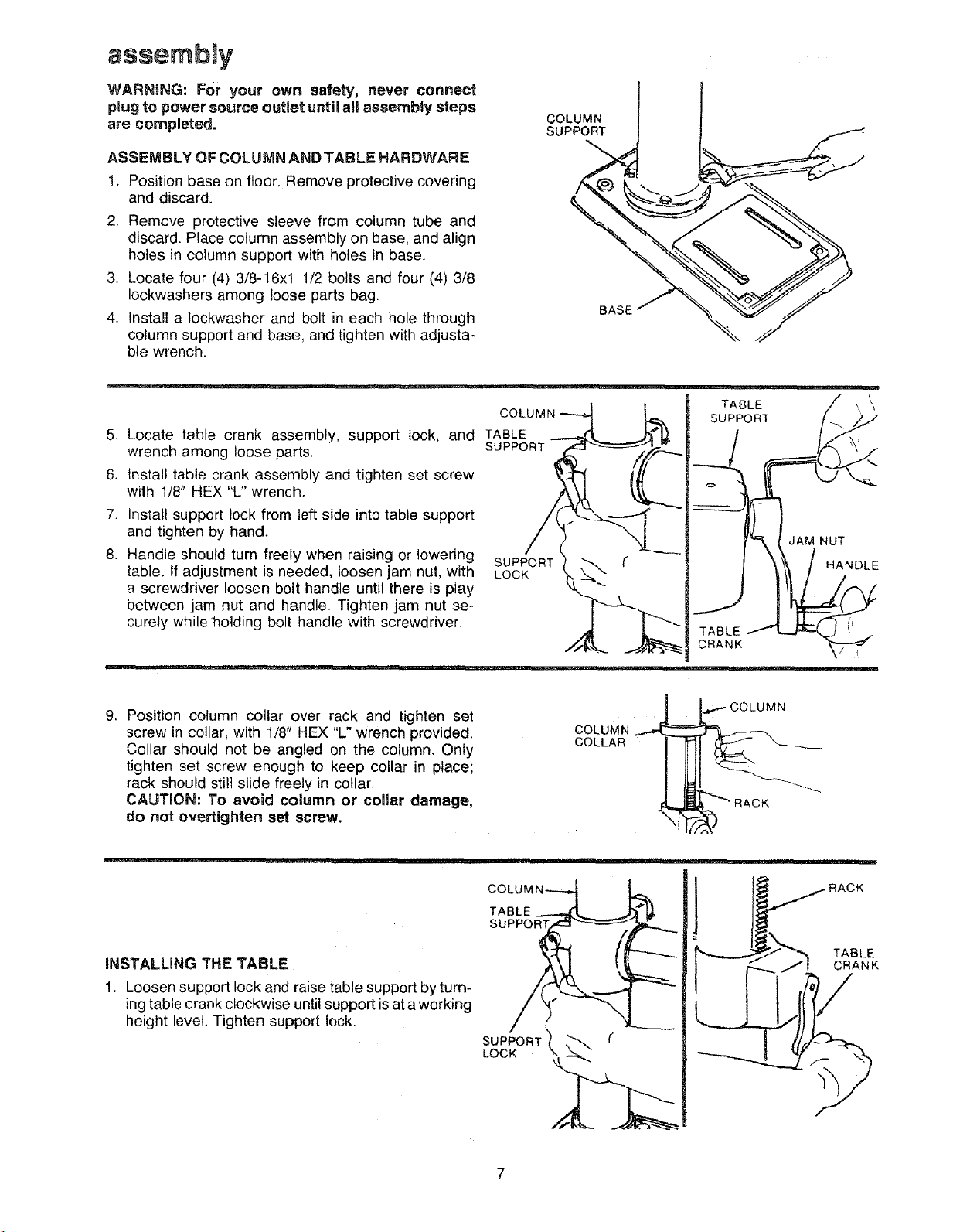
ASSEMBLY OF COLUMN AND TABLE HARDWARE
1. Position base on floor. Remove protective covering
and discard.
2. Remove protective sleeve from column tube and
discard. Place column assembly on base, and align
holes in column support with holes in base.
3. Locate four (4) 3/8-16xl 1/2 bolts and four (4) 3/8
Iockwashers among loose parts bag.
4. Install a Iockwasher and bolt in each hole through
column support and base, and tighten with adjusta-
ble wrench.
COLUMN
SUPPORT
BASE
COLUMN
TABLE _ \
SUPPORT
5. Locate table crank assembly, support lock, and TABLE
wrench among loose parts. SUPPORT
6. Install table crank assembly and tighten set screw
with 1/8" HEX "L" wrench.
7. Install support lock from left side into table support
and tighten by hand. JAMNUT
8. Handle should turn freely when raising or lowering SUPPORT HANDLE
table. If adjustment is needed, loosen jam nut, with LOCK
a screwdriver loosen bolt handle until there is play
between jam nut and handle. Tighten jam nut se-
curely while holding bolt handle with screwdriver.
9. Position column collar over rack and tighten set
screw in collar, with 1/8" HEX "L" wrench provided.
Collar should not be angled on the column. Only
COLUMN
COLLAR
COLUMN
tighten set screw enough to keep collar in place;
rack should still slide freely in collar.
CAUTION: To avoid column or collar damage,
i_'_ RACK _-"'-"--'_"
do not overtighten set screw.
INSTALLING THE TABLE
1. Loosen support lock and raise table support byturn-
ingtable crank clockwise until support isat a working
height level. Tighten support lock.
COLUM_
TABLE
SUPPORT
LOCK
,_,,.._ TABLE
CRANK
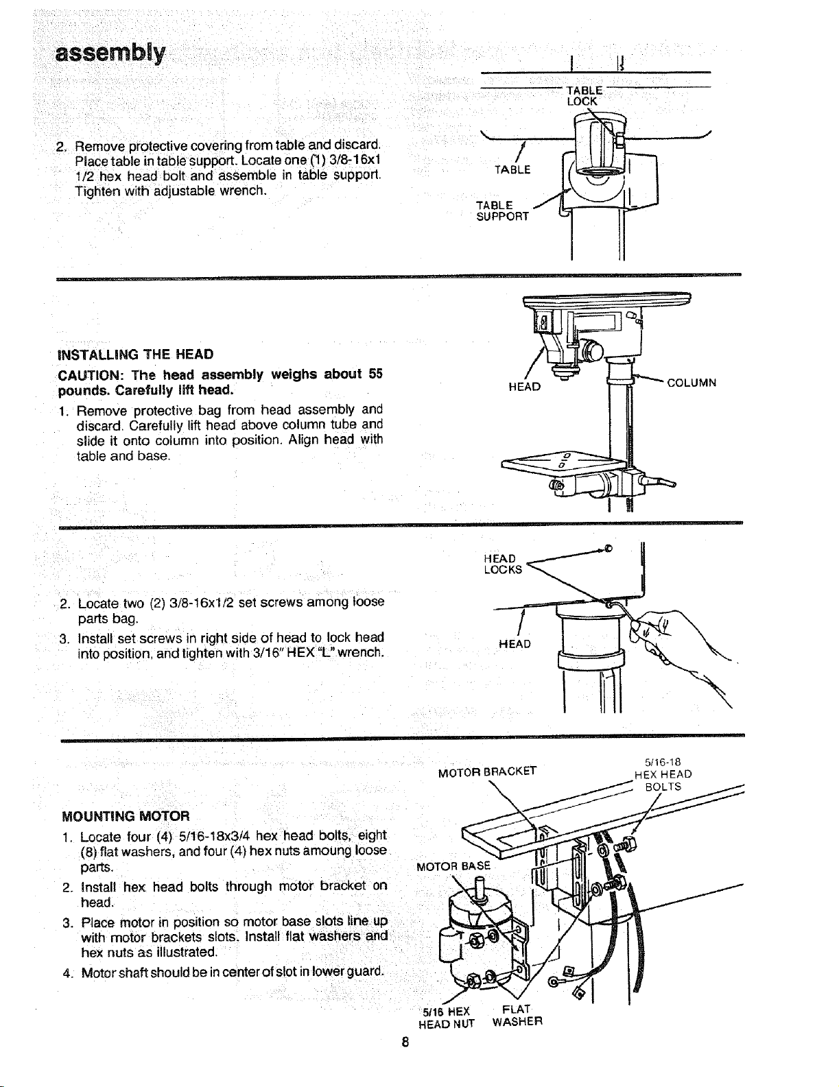
2. Remove protective covering from table and discard,
Place table in table support. Locate one ('1)3/8-16xl
1/2 hex head bolt and assemble in table support,
Tighten with adjustable wrench.
INSTALLING THE HEAD
CAUTION: The head assembly weighs about 55
pounds. Carefully lift head.
1. Remove protective bag from head assembly and
discard. Carefully lift head above column tube and
slide it onto column into position. Align head with
table and base.
\ /
TABLE
TABLE
SUPPORT
HEAD
I I!
TABLE
LOCK
.J
COLUMN
2. Locate two (2) 3/8-16xl/2 set screws among loose
parts bag.
3. Install set screws in right side of head to lock head
into position, and tighten with 3/16" HEX "L" wrench.
MOUNTING MOTOR
1. Locate four (4) 5/16-18x3/4 hex head bolts, eight
(8) flat washers, and four (4) hex nutsamoung loose
parts, MOTOR BASE
2. Install hex head bolts through motor bracket on
head.
3. Place motor in position so motor base slots line up
with motor brackets slots. Install flat washers and
hex nuts as illustrated.
4. Motor shaft shouldbe incenter of slot in lower guard.
HEAD
LOCKS
HEAD
MOTOR BRACKET
\
\
5t16-!8
HEX HEAD
BOLTS
5/16 HEX FLAT
HEAD NUT WASHER
8
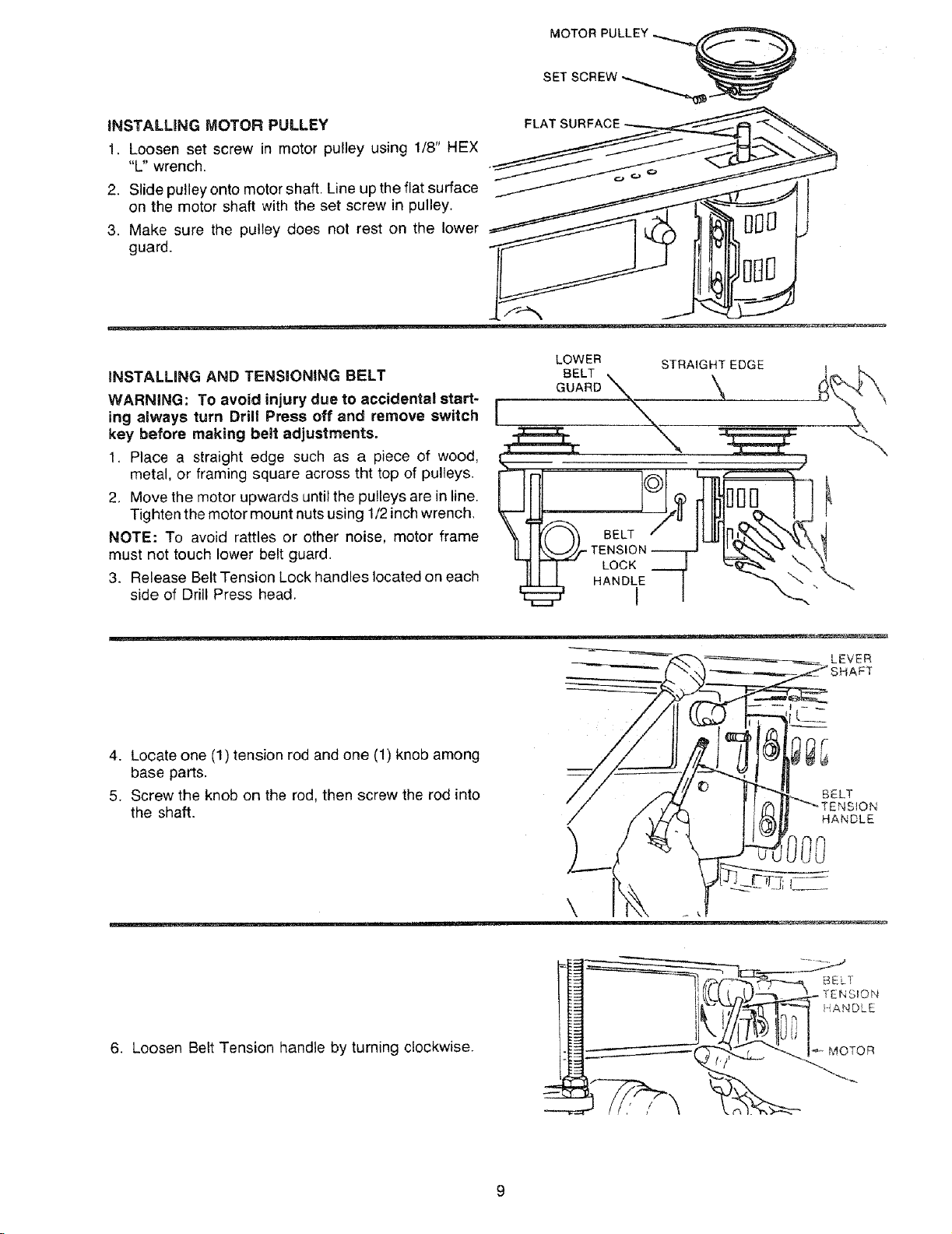
iNSTALLiNG MOTOR PULLEY
1. Loosen set screw in motor pulley using 1/8" HEX
"L" wrench.
2. Slide pulley onto motor shaft. Line up the flat surface
on the motor shaft with the set screw in pulley.
3. Make sure the pulley does not rest on the lower
guard.
INSTALMNG AND TENSIONING BELT GUARDBELTX
WARNING: To avoid injury due to accidental start-
key before making belt adjustments.
1. Place a straight edge such as a piece of wood,
2. Move the motor upwards until the pulleys are in line.
Tighten the motor mount nuts using 1/2inch wrench.
metaL or framing square across tht top of pu,leys. __BELT_t.. , , ,_,, ,,, ,_'_ __ !
must not touch lower belt guard.
3. Release Belt Tension Lock handles located on each
NOTE: To avoid rattles or other noise, motor frame _ 1[(_)) .._ / I_1_'_'_"_'_ __THELTCI _ __---IIL
side of Drill Press head. "_
FLAT SL
LOWER STRAIGHT EDGE t
4. Locate one(1)tensionrod and one (1)knob among
base pa_s.
5. Screw the knob on the rod, then screw the rodinto
the shaft.
w _.........
6. Loosen Belt Tension handle by turning clockwise.
LEVER
BELT
HANDLE
o
U
1 _
\
 Loading...