

Craftsman 113213710, 11321371 Owner’s Manual
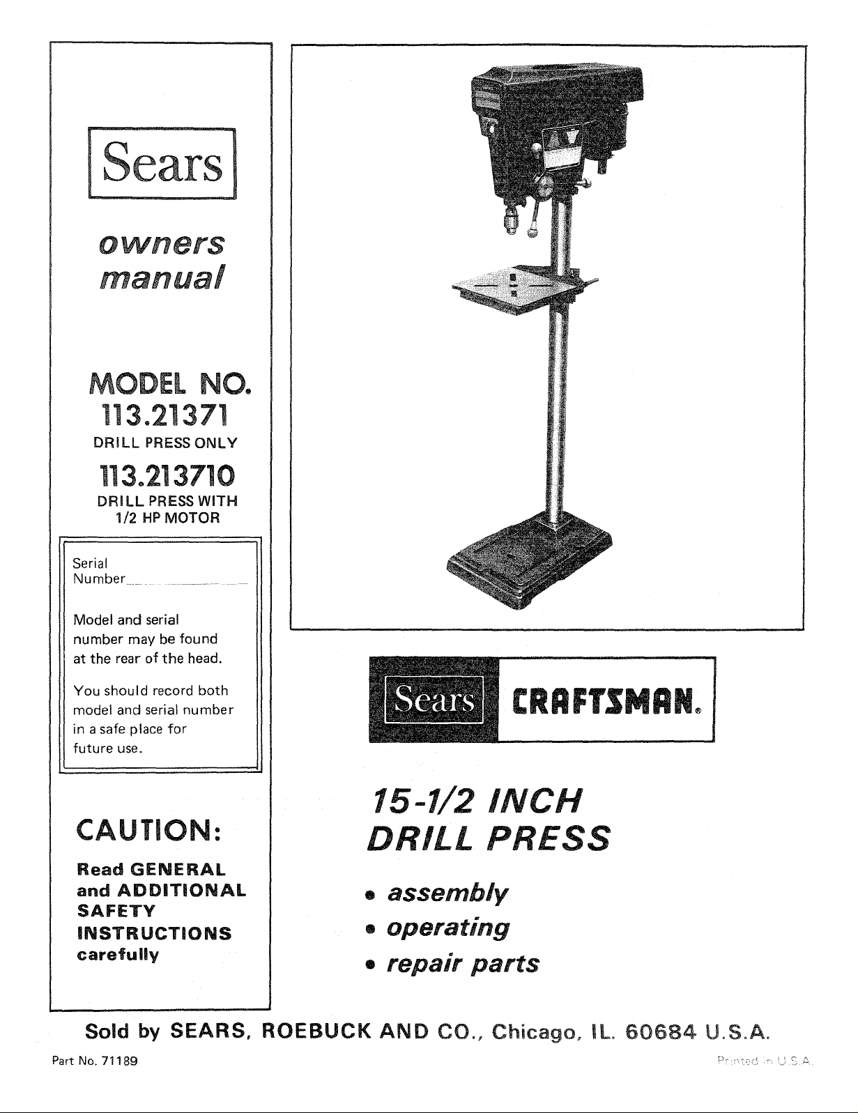
MODEL NO.
]]3.21371
DRILL PRESS ONLY
113.213710
DRI LL PRESS WITH
1/2 HP MOTOR
Serial
Number ......................
Model and serial
number may be found
at the rear of the head.
You should record both
model and serial number
in a safe place for
future use.
®
15-1/2 INCH
CAUTION:
Read GENERAL
and ADDITIONAL
SAFETY
INSTRUCTIONS
carefully
Sold by SEARS, ROEBUCK AND CO., Chicago, IL. 60684 U.S.A.
Part No. 71189 _" ' -::; _ / _. ;_
DRILL PRESS
• assembly
• operating
= repair parts
FULL ONE YEAR WARRANTY ON CRAFTSMAN DRILL PRESS
If within one year from the date of purchase, this Craftsman Drill Pressfails due to a defect in material or
workmanship, Searswill repair it, free of charge.
WARRANTY SERVICE IS AVAILABLE BY SIMPLY CONTACTING THE NEAREST SEARS STORE
OR SERVICE CENTER THROUGHOUT THE UNITED STATES.
This warranty givesyou specific legal rights, and you may also have other rights which vary from state to
state.
SEARS, ROEBUCK AND CO., Sears Tower, BSC 41-3, Chicago, IL 60684
general safety instructions
1. KNOW YOUR POWER TOOL
Read the owner's manual carefully. Learn its
application and limitations as well as the specific
potential hazards peculiar to this tool.
2. GROUND ALL TOOLS
This tool is equipped with all approved 3-conductor
cord and a 3-prong grounding type plug to fit the
proper groundingtvpe receptacle The green conductor 15.
in the cord _s the grounding wire. Never connect the
green wire to a live terminal.
3. KEEP GUARDS IN PLACE
in working order, and in proper adjustment and
alignment.
4. REMOVE ADJUSTING KEYS
AND WRENCHES
Form habit of checking to see that <evs and adjusting
wrenches are removed from tool before turning _t on
5. KEEP WORK AREA CLEAN
Cluttered areas and benches _nwte accidents. Floor
must not be slippery due to wax or sawdust,
6. AVOID DANGEROUS ENVIRONMENT
Don't use power tools in damp or wet locations or
expose them to rain. Keep work area well lighted.
Provide adequate surrounding work space. 19.
7. KEEP CHILDREN AWAY
AI visitors should be kept a safe distance from work
area.
8. MAKE WORKSHOP KID-PROOF
- with padlocks, master sw_tches, or by removing
starter keys.
9. DON'T FORCE TOOL
It wJtt do the job better and safer at the rate for which
tt was designed
10. USE RIGHT TOOL
Don't force tool or attachment to do a _oo it was not
designed for.
11. WEAR PROPER APPAREL
Do not wear loose clothing, gloves, neckties or jewelry
(rings, wrist watchesl to get caught m moving parts.
Nonslip footwear is recommended. Wear protective
hair covering to contain long hair, Roll long sleeves
above the el bow.
12. USE SAFETY GOGGLES (Head Protection)
Wear Safety goggles lmust compl_ with ANS Z87.1 ) at
all times. Also, use face or dust mask if cutting
operation ts dusty, and ear protectors (plugs or muffs)
during extended periods of operation.
{or power tools
13. SECURE WORK
Use clamps or a vise to hold work when practical. It's
safer than using your hand, frees both hands to operate
tool
14. DON'T OVERREACH
Keep proper footing and balance at all times.
MAINTAIN TOOLS WITH CARE
Keep tools shard and clean for best and safest
performance. Follow mstructtons for lubricating and
changing accessories
16. DISCONNECT TOOLS
before servicing; when changing accessories such as
blades, bits, cutters, etc.
17. AVOID ACCIDENTAL STARTING
Make sure switch is in "OFF" position before plugging
In.
18. USE RECOMMENDED ACCESSORIES
Consult the owner's manual for recommended
accessories Follow the instructions that accompany
the accessories. The use of _mproper accessories may
cause hazards.
NEVER STAND ON TOOL
Serious injury could occur if the tool is tipped or if the
cutting tool is accidentally contacted.
Do not store materials above or near the tool such that
it is necessary to stand on the tool to reach them.
20. CHECK DAIVIAGED PARTS
Before further use OT the tool. a guard or other part that
ts damaged should be carefully checked to ensure that it
will operate properly and perform its intended function.
Check for alignment of mowng parts, binding of moving
carts, breakage of parts, mounting, and any other
corlditions that may .affect its operation. A guard or
other cart that is damageo should be properly repaired
or re placed.
21. DIRECTION OF FEED
Feed work into a blade or cutter against the direction
of rotation of the blade or cutter only.
NEVER LEAVE TOOL RUNNING
22.
UNATTENDED
Turn oower off. Don't leave tool until it comes to a
complete stop.
additionam safety instructions for drill presses
WARNING: FOR YOUR OWN SAFETY, DO NOT
ATTEMPT TO OPERATE YOUR DRILL PRESS UNTIL
iT IS COMPLETELY ASSEMBLED AND iNSTALLED
ACCORDING TO THE INSTRUCTOONS . .. AND UNTaL
YOU HAVE READ AND UNDERSTAND THE
FOLLOWING:
1.
General Safety instructions for Power Tools Page 2
2.
Getting to Know Your Drill Press .......... Page 13
3.
Basic Drill Press Operation ............... Page 1(;
4.
Adjustments .......................... Page 17
5.
Maintenance .......................... Page 18
6.
Stability of Dritl Press
If there is any tendency for the drill press to tip over or
move during certain operations such as shaping, the drill
press should be bolted to the floor.
If the workpiece is too large to support with one hand,
provide an auxiliary support.
7,
Location
The drill press should be positioned so neither the
operator nor a casual observer is forced to stand in line
with a potential Kickback.
8.
Kickback
A kickback occurs when the workpiece is suddenly
thrown in the OPPOSITE direction to the DIRECTION
OF FEED; WHICH CAN CAUSE SERIOUS INJURY.
Kickbacks are most commonly caused by:
a. Relaxing your grip of the workpiece while
shaping or routing.
b. Taking too heavy a cut while shaping or routing.
c. Ignoring the instructions for shaping or routing.
9,
Protection: Eyes, Hands, Face, Ears, Body
WARNING: FOR YOUR OWN SAFETY DON'T
WEAR GLOVES WHEN OPERATING A DRILL
PRESS
a. If any part of your drill press is malfunctioning,
has been damaged or broken ... such as the
motor switch, or other operating control, a
safety device or the power cord ... cease
operating immediately until the particular part
is properly repaired or replaced.
b. Wear safety goggles that comply with ANS
Z87.1, and a face shield if operation is dusty.
Wear ear plugs or muffs during extended periods
of operation.
c. Never place your fingers in a position where
they could contact the drill or other cutting
tool (router bit, shaper cutter, etc.) if the
workpiece should unexpectedly shift. (For
instance, hold-down!push blocks must be used
when shaping on the drill press to keep hands
remote from the cutter if a kickback should
occur.)
d. Never operate drill press with protective cover
on the unused shaft end of the motor removed.
e. Position workpiece to butt against the column
whenever possible - if it is too short, clamp
solidly to the Table -- this is to prevent the drill
bit from grabbing the work from your hands,
which could result in personal injury. A drill
press vise must be fastened to the tabte.
f. Never perform any operation "free-hand"
(hand-holding workpiece rather than support it
on the Table), except wire brushing and
polishing -- Wear Safety Goggles. _
g, Never perform internal or curved shaping
operations. Perform straight line shaping ONLY
(with the Shaper Fence Accessory).
10, Use only accessories designed for this drill press.
11. Note and Follow the Safety Rules that Appear on the
12. Think Safety, Safety is a combination of operator
WARNING: DO NOT ALLOW FAMILIARITY (GAINED
THAT A CARELESS FRACTION OF A S[COND iS
h. Never perform any operation by moving the
Head or Table with respect to one another. Do
not pull the motor switch "ON" or start any
operation before checking that Head and Table
Lock Handles are clamped tight to Column, and
Head and Table Support Collars are correctly
positioned.
i. Before pulling the motor switch "'ON", be
positive the belt guard is down, the Chuck is
installed properly, and the drill or other cutting
tool is securely clamped in the chuck.
j. Before starting the operation, jog the motor
switch to be sure the drill or other cutting tool
does not have excessive runout or cause
vibration.
k. Do not operate the Drill Press unless the Depth
Stop and Stop Nut are instal!ed and the Depth
Stop clamped to the Depth Stop Rod.
I. Never pull out on the hub of the quill Hub
Assembly unless you first grasp and support the
Quill, otherwise the Quiti will drop and damage
may result.
m. Use the spindle speed recommended for the
specific operation and workpiece material -
refer to panel on right side of the Head for
drilling information, and for accessories, to the
instruction sheets that accompany the
accessories.
n. If workpiece overhangs the Table such that it
will fall to floor if unsupported, clamp it to the
Table or provide auxiliary support,
o. Use fixtures for unusual operations to
adequately hold, guide and position workpiece
for best quality and minimum hazard.
p. Be sure to lock Quill securely for all routing,
sanding, surfacing, shaping, and dovetailing
operations.
q. Never climb on the drill press Table.
r. Lock the motor Switch and put away the Key
when leaving the drill press.
s. DO NOT perform layout, assembly, or setup
work on the table while the cutting tool is
rotating.
a. Holesaws must NEVER be operated on this drill
press at a speed greater than 380 RPM,
b. Drum sanders must NEVER be operated on this
drill press at a speed greater titan 720 RPM.
c. Do not exceed the speed recommended for the
drill size in wood when using the mortising bit
and chisel.
(See chart on R.H. trim panel of the drill press.)
d. Do not install or use any drill that exceeds 7" in
length or extends 6" below the chuck jaws.
Panel on the Left Side of the Head:
DANGER: FOR YOUR OWN SAFETY: READ AND
UNDERSTAND OWNERS MANUAL BEFORE
OPERATING THIS MACHINE. WEAR SAFETY
GOGGLES, OO NOT WEAR GLOVES, SECURELY
CL_P WORK TO TABLE iF IT IS TOO SHORT TO
CONTACT THE COLUMN WHEN }N OPERATING
POSITION.
common sense and alertness at all times when the drili
press is being used.
FROM FREQUENT USE OF YOUR DRILL PRESS)TO
BECOME COMMONPLACE. ALWAYS REMEMBER
SUFF_C_E,NT TO iNFLICT SEVERE !N3!JRY,
additional safety instructions for drill presses
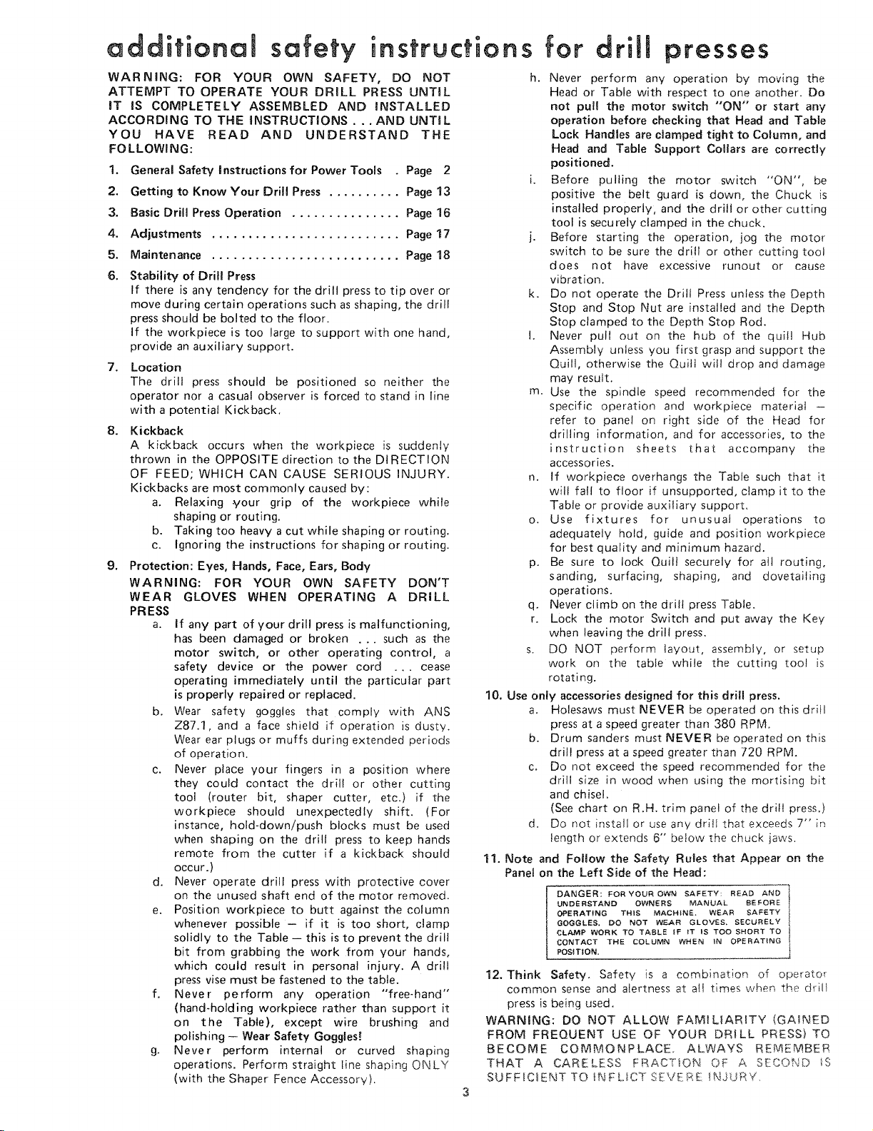
WEAR YOUR
The operation of any power tool can result in foreign
objects being thrown into the _yes, which can result in
severe eye damage. Always wear safety goggles complying
with ANSI Z87,1 (shown on Package) before commencing
power tool operation. Safety Goggles are available at Sears
retail or catalog stores.
unpacking
checking
CONTENTS
Page
General Safety Instructions for Power Tools ..... 2
Additional Safety Instructions for Drill Presses .... 3
Unpacking and Checking Contents ............. 4
Table of Loose Parts ........................ 4
Motor Specifications and Electrical Requirements.. 5
Assembly ................................. 6
Installing the Chuck .................... 6
Installing and Tensioning Belt ............. 12
Getting to Know Your Drill Press .............. 13
Belt Tension Rod ...................... 13
Drilling Speed ......................... 13
Drilling to Depth ....................... 14
Removing the Chuck ................... 15
On-Off Switch ........................ 15
Basic Drill Press Operation .................... 16
Installing Drills ........................ 16
Positioning Table and Workpiece .......... 16
Feeding ............................. 17
Adjustments ............................. 17
Depth Scale .......................... 17
Quil Return Spring .................... 17
Table and Head Lock Handles ............ 17
Maintenance .............................. 18
Lubrication .............................. 18
Recommended Accessories ................... 18
Trouble Shooting .......................... 19
Repair Parts ............................... 20
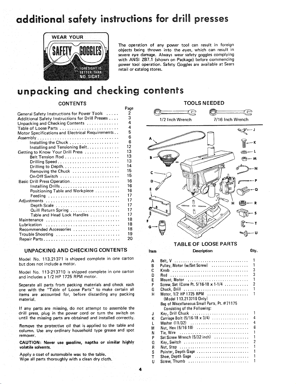
UNPACKING AND CHECKING CONTENTS
Model No. 113.21371 is shipped complete in one carton
but does not include a motor.
Model No. 113-2137!0 is shipped complete in one carton
and includes a 1/2 HP 1725 RPM motor.
Separate all parts from packing materials and check each
one with the "Table of Loose Parts" to make certain all
items are accounted for, before discarding any packing
material.
If any parts are missing, do not attempt to assemble the
drill press, plug in the power cord or turn the switch on
until the missing parts are obtained and installed correctly.
Remove the protective oil that is applied to the table and
column. Use any ordinary household type grease and spo_
remover.
CAUTION: Never use gasoline, naptha or similar highly
volatile solvents.
Apply a coat of automobile wax to the table.
Wipe a!t parts thoroughly with a clean dry cloth.
contents
TOOLS NEEDED
1/2 Inch Wrench 7/16 Inch Wrench
TABLE OF LOOSE PARTS
Item ]Description Qty.
A Belt, V .................................. 1
B Pulley, Motor (wjSet Screw) ................. !
C Knob ................................... 3
D Rod .................................... 3
E Mount,Motor ............................ 1
F Screw,Set (Cone Pt.5/16-18 x 1-1]4 ........... 2
G Chuck, Drill .............................. 1
H Motor,112 HP1725 BPM ................... t
(Model1 13.213710Only)
Bagof MiscellaneousSmallParts,Pt.#71175
Consistingof the Following:
J Key, Drill Chuck .......................... 1
K CarriageBolt (5/16-18 x 3/4) ................. 4
L Washer(11/32) ........................... 4
M Nut, Hex (5/16-18) ........................ 6
N Tie,Wire ................................ !
P SetScrewWrench(5/32 inch) ................ 1
Q Key,Switch .............................. 2
R Nut, Stop ................................ 1
S Pointer, Depth Gage ........................ 1
T Shoe,DepthGage ......................... 1
U Screw,Thumb ............................ 1
4
motor specifications and electrical requirements
MOTOR SPECRFICATIONS
This drill press is designed to use a 1725 RPM motor only.
Do not use any motor that runs faster than 1725 RPM.
It is wired for operation on 1!0-120 volts, 60 Hz.,
alternating current. IT MUST NOT BE CONVERTED TO
OPERATE ON 230 VOLTS, EVEN THOUGH THE
RECOMMENDED MOTORS ARE DUAL VOLTAGE.
THESE CRAFTSMAN MOTORS HAVE BEEN
FOUND TO BE ACCEPTABLE FOR USE ON
THiS TOOL.
HP RPM VOLTS CATALOG NO.
1/3 1725 110-120 1250
1/2 1725 110-120 !254
1/2 1725 !10-120 1255
1/2 1725 110-120 1278
1/2 1725 110q20 1279
CAUTBON: Do not use blower or washing machine motors
or any motor with an automatic reset overload protector as
their use may be hazardous.
CONNECTING TO POWER SOURCE OUTLET
This machine must be grounded while in useto protect the
operator from electric shock.
Plug power cord into a 110-120V properly grounded type
outlet protected by a 15-amp. time delay or Circuit-Saver
fuse or circuit breaker.
iF YOU ARE NOT SURE THAT YOUR OUTLET IS
PROPERLY GROUNDED, HAVE IT CHECKED BY A
QUALI FlED ELECTRICIAN.
WARNING: DO NOT PERMIT FINGERS TO TOUCH
THE TERMINALS OF PLUGS WHEN INSTALLING OR
REMOVING THE PLUG TO OR FROM THE OUTLET.
WARNING: iF NOT PROPERLY GROUNDED THIS
POWER TOOL CAN INCUR THE POTENTIAL HAZARD
OF ELECTRICAL SHOCK, PARTICULARLY WHEN
USED IN DAMP LOCATIONS, IN PROXIMITY TO
PLUMBING. iF AN ELECTRICAL SHOCK OCCURS
THERE iS THE POTENTIAL OF A SECONDARY
HAZARD SUCH AS YOUR HANDS CONTACTING THE
CUTTING TOOL.
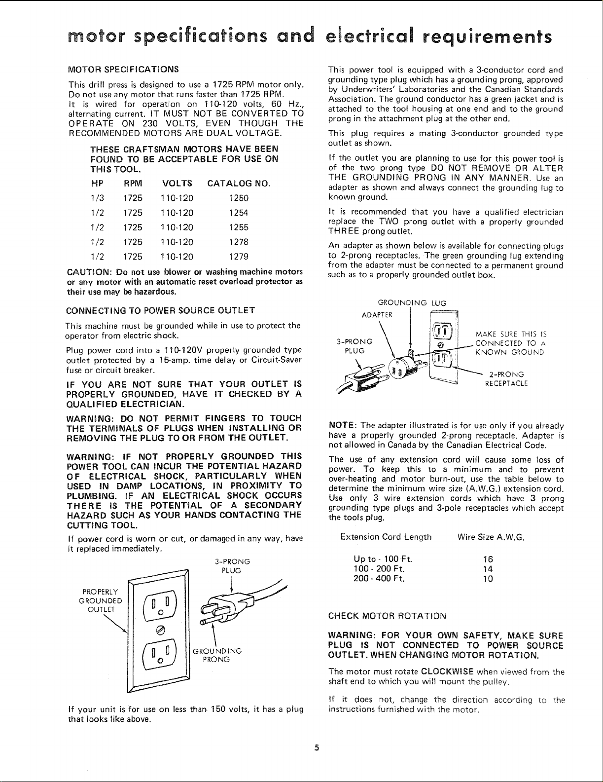
If power cord is worn or cut, or damaged in any way, have
it replaced immediately.
3-PRONG
PLUG
PROPERLY
GROUNDED
OUTLET
\
U
GROUNDING
PRONG
This power tool is equipped with a 3-conductor cord and
grounding type plug which has a grounding prong, approved
by Underwriters' Laboratories and the Canadian Standards
Association. The ground conductor has a green jacket and is
attached to the tool housing at one end and to the ground
prong in the attachment plug at the other end.
This plug requires a mating 3-conductor grounded type
outlet as shown.
if the outlet you are planning to use for this power toot is
of the two prong type DO NOT REMOVE OR ALTER
THE GROUNDING PRONG IN ANY MANNER. Use an
adapter as shown and always connect the grounding lug to
known ground.
It is recommended that you have a qualified electrician
replace the TWO prong outlet with a properly grounded
THREE prong outlet.
An adapter as shown below is available for connecting plugs
to 2°prong receptacles. The green grounding lug extending
from the adapter must be connected to a permanent ground
such as to a properly grounded outlet box.
GROUNDING LUG
ADAPTER t I__._-_
3-PRONG
NOTE: The adapter illustrated is for use only if you already
have a properly grounded 2-prong receptacle. Adapter is
not allowed in Canada by the Canadian Electrical Code.
The use of any extension cord will cause some loss of
power. To keep this to a minimum and to prevent
over-heating and motor burn-out, use the table below to
determine the minimum wire size (A.W.Go) extension cord.
Use only 3 wire extension cords which 'have 3 prong
grounding type plugs and 3-pole receptacles which accept
the tools plug.
Extension Cord Length Wire Size A.W.G.
Upto-lOOFt. 16
100-200 Ft. 14
200-400 Ft. 10
CHECK MOTOR ROTATION
WARNING: FOR YOUR OWN SAFETY, MAKE SURE
PLUG IS NOT CONNECTED TO POWER SOURCE
OUTLET. WHEN CHANGING MOTOR ROTATION.
The motor must rotate CLOCKWISE when viewed from the
shaft end to which you will mount the pulley.
MAKE SURETHIS IS
CONNECTED TO A
RECEPTACLE
If your unit is for use on less than t50 volts, it has a plug
that looks like above.
If it does not, change the direction according to the
instructions furnished with the motor.
assembly
WARNING: FOR YOUR OWN SAFETY, NEVER
CONNECT PLUG TO POWER SOURCE OUTLET UNTIL
ALL ASSEMBLY STEPS ARE COMPLETED,
1. Unwind the power cord.
2. Make sure the quill lock handle is tight.
3. Stand on, the left side of the drill press and LOOSEN
the HEAD LOCK HANDLE.
4. Raise the HEAD about HALF WAY up the column.
CAUTION: THE HEAD WEIGHS ABOUT 65 POUNDS
DROPPING THE HEAD ACCIDENTLY COULD CAUSE
PERSONAL INJURY OR DAMAGE THE DRILL PRESS.
5o TIGHTEN the Head Lock Handle.
6. Position the HEAD-SUPPORT COLLAR underneath
the head and tighten the TWO BOLTS using a ½"
wrench,
HEAD
LOCK HANDLE
HEAD SUPPORT
COLLAR
SPINDLE NOSE
IN ORDER TO RAISE THE HEAD TO A HIGHER
POSITION, IT WILL BE NECESSARY TO INSTALL
SEVERAL PARTS.
INSTALLING THE CHUCK
Clean out the TAPERED HOLE in the chuck; clean the
spindle nose with a clean cloth Make sure there are no
foreign particles sticking to the surfaces. The slightest
piece of dirt on the spindle nose or in the chuck will
prevent the chuck from seating properly. This will cause
the drill to "wobble."
6
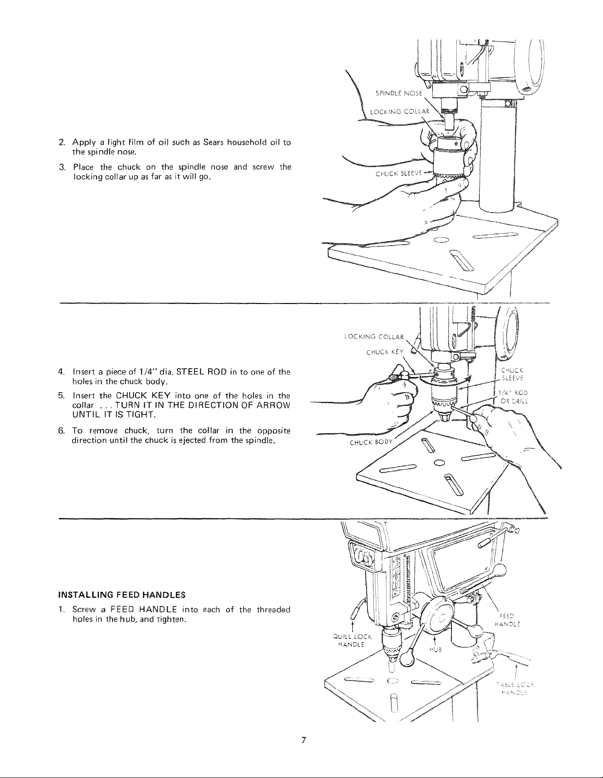
2. Apply a light film of oil such as Sears household oil to
the spindle nose.
3. Place the chuck on the spindle nose and screw the
locking collar up as far as it will go.
SPINDLE NOSE
LOCKING COLLAR
CHUCK
4. Insert a piece of 1/4" dia. STEEL ROD in to one of the
holes in the chuck body.
5. Insert the CHUCK KEY into one of the holes in the
collar ...TURN IT IN THE DIRECTION OF ARROW
UNTIL IT IS TIGHT.
6. To remove chuck, turn the collar in the opposite
direction until the chuck is ejected from the spindle.
iNSTALLING FEED HANDLES
1. Screw a FEED HANDLE into each of the threaded
holes in the hub, and tighten.
LOCKING COLLAR
CHUCK KEY
CHUCK BODY
t
QUILL LOCK
HANDLE
N
\
t
/
assembly
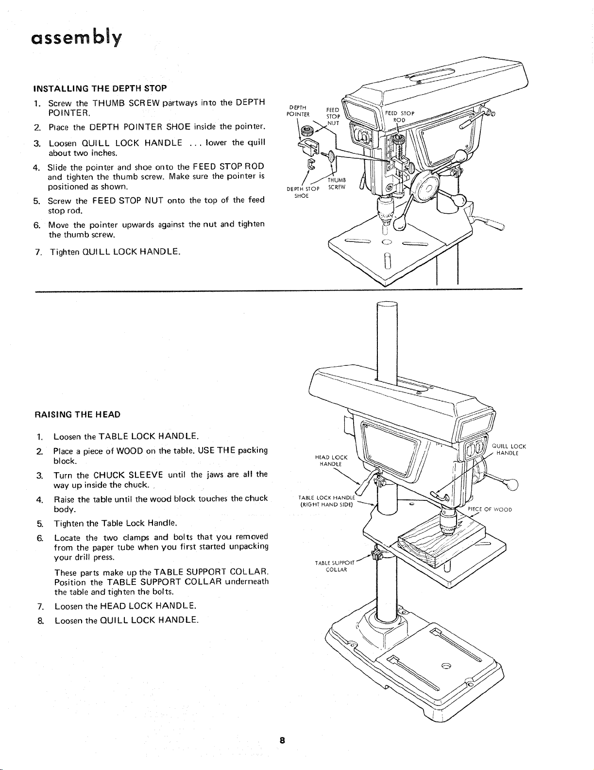
INSTALLING THE DEPTH STOP
1. Screw the THUMB SCREW partways into the DEPTH
POINTER.
2. Place the DEPTH POINTER SHOE inside the pointer.
3. Loosen QUILL LOCK HANDLE ... lower the quill
about two inches.
4. Slide the pointer and shoe onto the FEED STOP ROD
and tighten the thumb screw. Make sure the pointer is
positioned as shown,
5. Screw the FEED STOP NUT onto the top of the feed
stop rod.
6. Move the pointer upwards against the nut and tighten
the thumb screw.
7. Tighten QUILL LOCK HANDLE.
DEPTH
POINTER
DEPTH STOP
SHOE
FEED f
STOP
RAISING THE HEAD
1. Loosen the TABLE LOCK HANDLE.
2. Place a piece of WOOD on the table. USE THE packing
block.
3. Turn the CHUCK SLEEVE until the jaws are all the
way up inside the chuck.
4. Raise the table until the wood block touches the chuck
body.
5. Tighten the Table Lock Handle.
6. Locate the two clamps and bolts that you removed
from the paper tube when you first started unpacking
your drill press.
These parts make up the TABLE SUPPORT COLLAR.
Position the TABLE SUPPORT COLLAR underneath
the table and tighten the bolts,
7. Loosen the HEAD LOCK HANDLE.
8, Loosen the QUILL LOCK HANDLE.
HEAD LOCK
HANDLE
(RIGHT HAND SIDE)
TAE
COLLAR
QUILL LOCK
HANDLE
PIECE OF WOOD
 Loading...