

Page 1
OPERATING iNSTRUCTIONS
AND PARTS LiST FOR
CrBftsrnan
Model Number 109.22620
This is the medal number of your Bufilder'sSaw. It wiU be Eomld
on a plate located on the rear pand. Always numtion _ num-
b_ when communicating with us regarding your Build_s Saw
when orating p_.
HOW TO ORDER PARTS FOR
MODEL HUMBER 109.22620
AU parts listed here mint be ordered throtlgh a Sears Ret_ or
M_ Order Store° Parts are shipped p_Lvald° When
parts always give the following information:
le
2.
3.
Part number°
Part name and price.
Model number which is
109.22620, and will be
found on a plate on the
rear pand.
Th_ llst is valuable. It wW assure your being ab|e to dbtain
proper part, service. We su_t yon keep it with other valuab|e
papa_.
SEARS, ROEBUCK AND CO.
OCTOBER, 1946
Page 2
Page 3

Page 4

Page 5

Instructions for Assembling
Un©rafing
Your C_man Bu_der's Saw is shipped complete
(less motor) in one crate, with a carton for miscellaneous
parts inside the crate. Remove nails around sides 'at
bottom d crate. The top and sldes can then be lihed
off. Remove bol_ in legs from bottom of the crate
and lift saw off. h_tructlous for removing are also
printed on the crate. The carton between the legs cou-
talns the rip fence, lah-hand miter, right-hand miter,
saw guard_ splitter, dust bag, switch, pulleys and bdu,
and an envdope with the necessary small parts such as
nu_, etc., needed for assembly.
Assembly
Your Builder's Saw has been assembled, operated,
and inspected at the factory. The saw carriage has been
fastened securely for shipment. There is a pin attached
with a chain to the leh-hand side d the carriage that
locks the carriage for ripping and dado purpeees at
three points. The carriage Is now locked and fastened.
Open side door removing pin and fastening, so car-
riage can be moved. Mount your motor on the motor
support plate with the motor shah and saw spindle
lined up so that the saw is turning TOWARD the
operator. We have supplied slots in the motor support
plate that will accommodate the holes in most motor
bases. However if they do not fit your motor base,
use the ones that do agree and drill any others that
are necessary° For efficient operation use a 3450 R.PoM.
motor of not less than _ HiP. Any difference in the_
R.P.M. of your motor can be taken care of by usingr
different slz_ of pulleys in accordance with the fol-
lowing table:
Saw Spin_© Motor Motor Appl_ox.
Dia. PuUcy PuUcy R.P,M. Spin.g.P.M.
8 2V2 3gz 3450 48O0
8 2½ 6_ 1750 48O0
10 2V2 3 3450 4200
I0 2_/2 6 1750 42O0
-- --- 7
SRW
Travel
17Y2
17Yz
15½
15½
2¼
2¼
3¼
3¼
Motor should have a _/_-inch shaft with a 3/16-inch key-
way. After mounting the motor, fasten the 3-inch or
doublesheavepulleyson themotor shaftand puton the
two brits.Ifthebritsfurnishedarenotthe fightlength
you can probablyget the lengthyou need at your
nearest Sears Retail or Mail Order Store. Length of
belt is determined by measuring over the OUTSIDE
diameter of the pulley after iustallation. An adjustment
for tightening brits will be found at the rear of the
motor support plate. Do not have the balls too tight.
The switch is mounted with two screws to the front
panel. The following data should be followed for de.
retraining the size of wire recommended for the proper
operation d motor:
MOTOR
H.P.
1
1
1½
MOTOR
VOLTAGE
115
230
115
230
115
230
D]STANCE FROM OUTLET
TO MOTOR
50-feet
No. 14
No. 14
No. 14
No. 14
No. 12.
No. 14
100-f_ 150-feet
No. 12 No. 10
No, 14, No. 14
No. I0 No. 8
No. 14 No. 12
No. 8 No. 6
No. 14 No. 12
and Operatin8 Your Saw
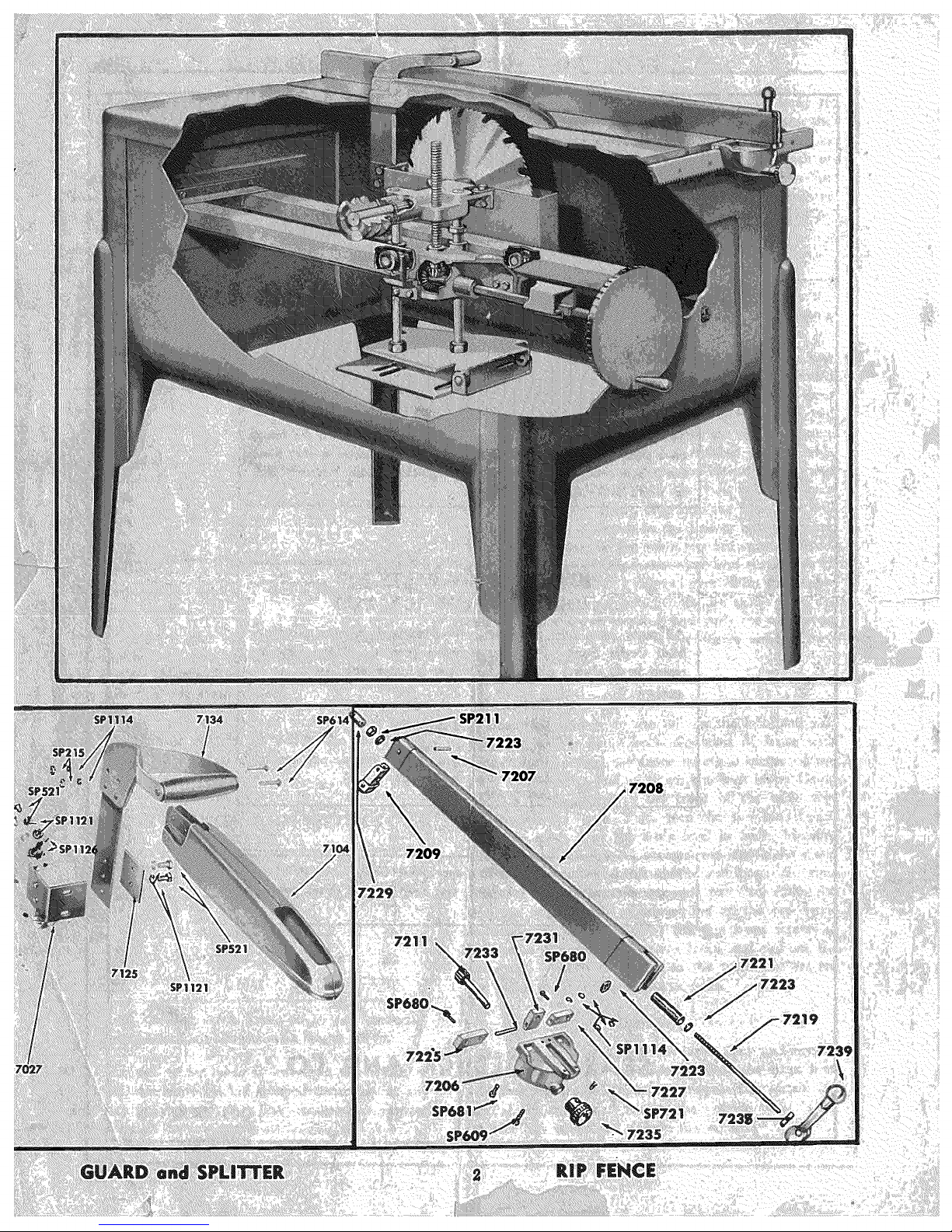
Bolt the splitter angle bracket part No. 7027 to the rear
of the dust chute. Drop the splitter blade, with handl_
over the saw, through the saw slot in the top of the
table. Bolt it with the splitter retaining plate part No.
7125 to the angle bracket part No. 7027. The splitter
blade must be directly in llne with the saw blade. Bolt
guard to the spliRerblade.
The six-inch hand wheel at the front will raise and
lowerthe entire assembly, consisting of saw blade, split°
ter, guard, and handle, to the required height above the
table. The guard should not be more than _ inch
above the work passing _gh saw blade.
The fence guide bar part No. 7121 should be checked
to be sure it has not ja_ed out of llne in shipment. If
so,line up paralidwiththe tabletopand tightenthe
sk mounting screws. For attaching the rip _ence to the
table top, pull out on the small pinion gear knob No.
7235, and slide the fence overthe gmda bar. The fence
may now be moved back and forth by hand. For fin_
adjus_nent engage the piniongear with fence guide bar
by pushing in the knob. The fence can be locked _ront
and back by pushing down on lever No. 7239. If clamp-
ing action is not as tight as desired it may be adjusted
by the jam nuts on the rear end of the tie rod that
runs through the complete fence.
Cumin9 Capa¢i
The depth of cut is controlled by raising and lower-
ing the saw blade using the hand wheel located on
the front panel. The saw can be set to cut thicknesses
from "0" to 3¼ inches. The maximum saw carriage
t_avd is 15_ inches.
Lubrication
Greesin_
The spindle bearings are lubricated at the [ac_
and will' give you approximately 1000 hours of use be-
fore they need to be lubricated. In the housing
the spindlebearings there is a Zerk type fitting which
may be reached from the lab-hand door. Use a ha_
type grease gun, with any high-pressure chassis gun
grease. Do not PACK bearings.
Oi|in_
The followlng parts should be oiled frequently with
No. 20 or No. 30 _utomobile engine oil:
1. Saw raising screw and _,
2. The miter gear sha_ part No. 7063.
3. The hexagon sha_ part No. 7045.
4. Oil poin_ where there is f_ic_io_
between two ormore moving sm_ces
or when a slipfitisnec_sary such
as where the fence _lidas, etc.
To preventsaw table and saw from _th_g, keep
them covered with a film of oll when not in we a_
wipe off before using.
5
Page 6

Operating Instructiom---Continued
This saw is particularly designed for cutting long
pieces. Crosscutting plates, studding, perlim and joists
is fast and accurate, became the work is held against
the miter gage and the blade is pulled through. Mak-
ing the plumb cuts on common and principal rafters,
for roofs of any pitch, is accomplished by setting the
miter gage. The accompanying table shows the proper
miter gage setting for the more common roof pitches.
TABLE OF MITER GAGE SETTINGS FOR
CUTTING RAFTERS
Inches rise per
ft. of mn
6
7
8
9
10
11
12
Degrees to be set
on Miter Gage
63
60
/ 56
50
47zA
45
The same method applies to cutting the ends of raft-
ers for box coruiceL
Rough stair m_ngers are quickly cut by making all
the _ ms and then moving the miter gage 90 de-
gzees for all the tread cuts. Notching of rafters is
accomplished in the same manner.
Bridging is handled with one setting of the miter
gage. The various degrees at which the miter gage
is set for joists of different widths are shown in the
table.
TABLE OF MITER GAGE SETTINGS
FOR BRIDGING
Joist Size
Inches
2x 6
2x 8
2x 10
2x 12
Inches
13¼
16
17
18¼
Degrees on
MiterGage
73
68
62
57
The same methods as reed for roughing-in apply to
finishing. In cases where wide panels are to be cut, the
mit_ gage can be removed and the carriage locked on
the rails. The work can then be fed through, with or
without the rip fence, exactly as on a bench saw. For
dadoing across such parts as drawer fronts, the splitter
and guard can be removed and the carriage locked on
the rails.
Cross Cutting with Miter
The right-hand miter slides in the groove on the
rig_-hand side of the table and is reed for pmhing
the work through the saw.
The left-hand miter is used when pulling the saw
through the work. The table top has been provided
with two pivot positions to accommodate the left-hand
mi_er gage. Put pivot pin part No. 7407 in the keyed
hole closest to the operator. Then line up the double
end pointer with the angle line marked on the table
that is the dosast to the angle you intend cutting and
loosen knob part No. 7303. The two pins in clamp
assembly No. 7404 should drop into the holes that will
hdd the miter the closest to the line of cut you want.
The division lines on the table top are spaced 15 de-
apart. The scale on the miter arm represents 15
•_Tees, with markings 1 degree apart. With the double
_d pointer still in alignment, set the pointer on the
_i'__n scale at the end marking and push the arm along
until the pointer is on the exact degree needed_ then
tighten the handle.
Ripping
Lock the carriage to the rail on the left-hand side
_th the locking pin. Check alignment of fence with
the blade, by sliding the fence within 2 inches of the
blade and lock by pulling down the lock lever. Using
the saw tooth closest to the front of the table top,
measure to the fence. Then turn the saw blade until
the same tooth is at the table level in back. Measure
to the fence. The two measurements should be alike.
If not, take the fence off the table and loosen the four
screws under the front fence guide part No. 7206. Re-
turn the fence to the table and line up the saw fence
as mentioned above. Tighten the two front screws to
hold your adjustment. Remove fence and tighten the
other two. Attach the fence to the table and set for
the width of cut you propose to make.
Based on 1½ inch stock. Joists on 16-inch center.
One-quarter inch allowance on length for fit.
When the cut to be made is less than the width of
the board, the blade can be stopped accurately at any
point such as the end of a line because it is always
visible through the saw guarcL
Dadoing
To use a dedo head, take out insert plate and remove
the saw blade. Place one dndo blade on the arbor first,
_nd then theinsidechippersas requiredto obtain the
desired thickness, and finally, the outside dado blade.
Replace saw collar and tighten nut securely.
 Loading...