

Craftsman 107289930 Owner’s Manual

Operator's ManuaJ
®
Zero-Turn Rear Engine Riders with Electric Start
ModeJ No.
107.289930 (26HP Kohler Engine with 52" Mower}
CAUTmON: Before using this product, read
the manual and follow all its Safety Rules
and Operating Instructions.
For answers to your questions about this
product, cat1:
1°800°659°5917
Sears Craftsman Help Line
5 am- 5 pm, Mon- Sat
Nota: Una traducci6n en espa_ol de este Manual
del Operador puede encontrarse en la p_gina 37.
Sears, Roebuck and Co., Hoffman Estates, IL 60179
Visit our Craftsman website: www.sears.comicraftsman
U.S.A.
7103218
Revision -
Rev. Date 02/2009

2

Warranty Statement ..................................................... 3
Safety Rules & Information ......................................... 4
Identification Numbers ................................................ 9
Assembly .................................................................... 10
Pre-Operation ............................................................. 13
Operation .................................................................... 14
Maintenance ............................................................... 21
Service & Adjustments ............................................. 29
Storage ....................................................................... 34
Specifications ............................................................ 34
Troubleshooting ......................................................... 35
Spanish Operator's Manual ...................................... 37
Repair Parts ......................................................... PTS-1
Hardware and Torque Specifictions ................. PTS-36
Repair Protection Agreement ........Inside Back Cover
Service Numbers ........................................ Back Cover
NOTE: In this manual, "left" and "right" are
CRAFTSMAN LIMITED WARRANTY
TWO YEARS ON TRACTOR
When operated and maintained according to all supplied instructions, if thistractor fails due to a defect in material or
workmanship within two years from the date or purchase, call 1-800-4-MY-HOME® to arrange for free repair.
During the first year of purchase, there will be no charge for warranty service in your home. For your convenience,
in-home warranty service will still be available after the first year of purchase, but a trip charge will apply. This charge
will be waived if you transport the tractor to an authorized Craftsman drop-off location. For the nearest authorized
location, call 1-800-4-MY-HOME®.
90 DAYS ON BATTERY
For ninety (90) days from date of purchase, if the battery included with this tractor is defective in material or workman-
ship (our testing proves it will not hold a charge), it will be replaced free of charge in your home.
This warranty covers ONLY defects in material and workmanship. Sears will NOT pay for:
• Expendable items that become worn during normal use, including but not limited to blades, spark plugs, air
cleaners, belts, and oil filters.
• Standard maintenance servicing, oil changes, or tune-ups.
• Tire replacement or repair caused by punctures from outside objects, such as nails, thorns, stumps, or glass.
• Tire or wheel replacement or repair resulting from normal wear, accident, or improper operation or maintenance.
• Repairs necessary because of operator abuse, including but not limited to damage caused by towing objects
beyond the capability of the tractor, impacting objects that bend the frame or crankshaft, or over-speeding the
engine.
• Repairs necessary because of operator negligence, including but not limited to, electrical and mechanical dam-
age caused by improper storage, failure to use the proper grade and amount of engine oil, failure to keep the
deck clear of flammable debris, or failure to maintain the equipment according to the instructions contained in
the operator's manual.
• Engine (fuel system) cleaning or repairs caused by fuel determined to be contaminated or oxidized (stale). In
general, fuel should be used within 30 days of its purchase date.
• Normal deterioration and wear of the exterior finishes, or product label replacement.
All tractor and battery warranty coverage is void if this product is ever used for commercial or rental purposes.
This warranty applies only while this product is within the United States.
This warranty gives you specific legal rights, and you may also have other rights which vary from state to state.
Sears, Roebuck and Co., Hoffman Estates, IL 60179
referred to as seen from the operating position.
3
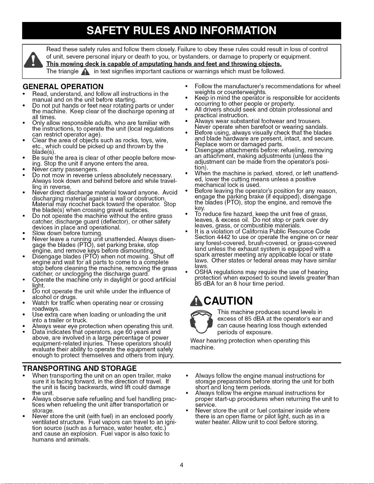
Readthesesafetyrulesandfollowthemclosely.Failuretoobeytheserulescouldresultinlossofcontrol
ofunit,severepersonalinjuryordeathtoyou,orbystanders,ordamagetopropertyorequipment.
This mowing deck is capable of amputating hands and feet and throwing objects.
The triangle d_, in text signifies important cautions or warnings which must be followed.
GENERAL OPERATION
• Read, understand, and follow all instructions in the
manual and on the unit before starting.
• Do not put hands or feet near rotating parts or under
the machine. Keep clear of the discharge opening at
all times.
• Only allow responsible adults, who are familiar with
the instructions, to operate the unit (local regulations
can restrict operator age).
• Clear the area of objects such as rocks, toys, wire,
etc., which could be picked up and thrown by the
blade(s).
• Be sure the area is clear of other people before mow-
ing. Stop the unit if anyone enters the area.
• Never carry .passengers.
• Do not mow in reverse unless absolutely necessary.
Alwa.ys look down and behind before and while travel-
ling in reverse.
• Never direct discharge material toward anyone. Avoid
discharging material against a wall or obstruction.
Material may ricochet back toward the operator. Stop
the blade(s) when crossing gravel surfaces.
• Do not operate the machine without the entire grass
catcher, discharge guard (deflector), or other safety
devices in place and operational.
• Slow down before turning.
• Never leave a running unit unattended. Always disen-
gage the blades (PTO), set parking brake, stop
engine, and remove keys before dismounting.
• Disengage blades (PTO) when not mowing. Shut off
engine and wait for all parts to come to a complete
stop before cleaning the machine, removing the grass
catcher, or unclogging the discharge guard.
• Operate the machine only in daylight or good artificial
light.
• Do not operate the unit while under the influence of
alcohol or drugs.
• Watch for traffic when operating near or crossing
roadways.
• Use extra care when loading or unloading the unit
into a trailer or truck.
• Always wear eye protection when operating this unit.
• Data indicates that operators, age 60 years and
above, are involved in a large percentage of power
equipment-related injuries. These operators should
evaluate their ability to operate the equipment safely
enough to protect themselves and others from injury.
• Followthe manufacturer's recommendations for wheel
weights or counterweights.
• Keep in mind the operator is responsible for accidents
occurring to other people or property.
• All drivers should seek and obtain professional and
practical instruction.
• Always wear substantial footwear and trousers.
Never operate when barefoot or wearing sandals.
• Before using, always visually check that the blades
and blade hardware are present, intact, and secure.
Replace worn or damaged parts.
• Disengage attachments before: refueling, removing
an attachment, making adjustments (unless the
adjustment can be made from the operator's posi-
tion).
• When the machine is parked, stored, or left unattend-
ed, lower the cutting means unless a positive
mechanical lock is used.
• Before leaving the operator's position for any reason,
engage the parking brake (if equipped), disengage
the blades (PTO), stop the engine, and remove the
key.
• To reduce fire hazard, keep the unit free of grass,
leaves, & excess oil. Do not stop or park over dry
leaves, grass, or combustible materials.
• It is a violation of California Public Resource Code
Section 4442 to use or operate the engine on or near
any forest-covered, brush-covered, or grass-covered
land unless the exhaust system is equipped with a
spark attester meeting any applicable local or state
laws. Other states or federal areas may have similar
laws.
• OSHA regulations may require the use of hearing
protection when exposed to sound levels greater than
85 dBA for an 8 hour time period.
This machine produces sound levels in
excess of 85 dBA at the operator's ear and
can cause hearing loss though extended
periods of exposure.
Wear hearing protection when operating this
machine.
TRANSPORTING AND STORAGE
• When transporting the unit on an open trailer, make
sure it is facing forward, in the direction of travel. If
the unit is facing backwards, wind lift could damage
the unit.
• Always observe safe refueling and fuel handling prac-
tices when refueling the unit after transportation or
storage.
• Never store the unit (with fuel) in an enclosed poorly
ventilated structure. Fuel vapors can travel to an igni-
tion source (such as a furnace, water heater, etc.)
and cause an explosion. Fuel vapor is also toxic to
humans and animals.
• Always follow the engine manual instructions for
storage preparations before storing the unit for both
short and long term periods.
• Always follow the engine manual instructions for
proper start-up procedures when returning the unit to
service.
• Never store the unit or fuel container inside where
there is an open flame or pilot light, such as in a
water heater. Allow unit to cool before storing.
SLOPE OPERATION
Slopes are a major factor related to loss-of-control and tip-
over accidents, which can result in severe injury or death.
Operation on all slopes requires extra caution. If you cannot
back up the slope or if you feel uneasy on it, do not operate
on it.
Control of a walk-behind or ride-on machine sliding on a
slope will not be regained by the application of the brake.
The main reasons for loss of control are: insufficient tire
grip on the ground, speed too fast, inadequate braking, the
type of machine is unsuitable for its task, lack of awareness
of the ground conditions, incorrect hitching and load distri-
bution.
• Mow across slopes, not up and down.
• Watch for holes, ruts, or bumps. Uneven terrain could
overturn the unit. Tall grass can hide obstacles.
• Choose a slow speed so that you will not have to stop
or change speeds while on the slope.
• Do not mow on wet grass. Tires may loose traction.
• Never mow down slopes.
• Avoid starting, stopping, or turning on a slope. If tires
lose traction (i.e. machine stops forward motion on a
slope), disengage the blade(s) (PTO) and drive slow
off the slope.
• Keep all movement on slopes slow andgradual. Do
not make sudden changes in speed or direction,
which could cause the machine to rollover.
• Use extra care while operating machines with grass
catchers or other attachments; they can affect the
stability of the unit. Do not use on steeps slopes.
• Do not try to stabilize the machine by putting your
foot on the ground (ride-on units).
• Do not mow near drop-offs, ditches, or embank-
ments. The mower could suddenly turn over if a
wheel !s over the edge of a cliff or ditch, or if an edge
caves in.
• Do not use grass catchers on steep slopes.
• Do not mow slopes if you cannot back up them.
• See your authorized dealer/retailer for recommenda-
tions of wheel weights or counterweights to improve
stability.
• Remove obstacles such as rocks, tree limbs, etc.
• Use slow speed. Tires may lose traction on slopes
even through the brakes are functioning properly.
• Do not turn on slopes unless necessary, and then,
turn slowly and gradually uphill, if possible. Never
mow down slopes.
, WARNING
Never operate on slopes greater than 17.6 percent
(10°) which is a rise of 3-1/2 feet (106 cm) vertically in
20 feet (607 cm) horizontally.
Select slow ground speed before driving onto slope.
Use extra caution when operating on slopes with rear-
mounted grass catchers.
Mow across the face of slopes, not up and down,use
caution when changing directions and DO NOT
START OR STOP ON SLOPE.
CHILDREN
Tragic accidents can occur if the operator is not alert to the
presence of children. Children are often attracted to the unit
and the mowing activity. Never assume that children will
remain where you last saw them.
• Keep children out of the mowing area and under the
watchful care of another responsible adult.
• Be alert and turn unit off if children enter the area.
• Before and during reverse operation, look behind and
down for small children.
• Never carry children, even with the blade(s) off. They
may fall off and be seriously injured or interfere with
safe unit operation. Children who have been given
rides in the past may suddenly appear in the mowing
area for another ride and be run over or backed over
by the machine.
• i'_everallow children to operate the unit.
• Use extra care when approaching blind corners,
shr.ubs, trees, or other objects that may obscure
vision.
EMISSIONS
• Engine exhaust from this product contains chemicals
known, in certain quantities, to cause cancer, birth
defects, or other reproductive harm.
• Look for the relevant Emissions Durability Period and
Air Index information on the engine emissions label.
IGNITION SYSTEM
• This spark ignition system complies with Canadian
standard ICES-O02.
TOWED EQUIPMENT (RIDE-ON UNITS)
• Tow only with a machine that has a hitch designed for
towing. Do not attach towed equipment except at the
hitch point.
• Followthe manufacturer's recommendations for
weight limit for towed equipment and towing on
slopes. See attaching a trailer under OPERATION.
• Never allow children or others in or on towed equip-
ment.
• On slopes, the weight of the towed equipment may
cause loss of traction and loss of control.
• Travel slowly and allow extra distance to stop.
• Do not shift to neutral and coast down hill.
5

SUGGESTED GUmDEFOR SmGHTmNGSLOPES FOR SAFE OPERATmON
ONLY RiDE UP AND DOWN HILL,
NOT ACROSS HiLL
WARNmNG: To avoid serious injury, operate your unit up and
down the face of smopes, never across the face. Do not operate
on smopes greater than 10 degrees. Make turns graduamly to
prevent tipping or _oss of control Exercise extreme caution
when changing direction on slopes. Braking may be affected by
attachments. Reduce speed on slopes.
1. Fold this page along dotted line indicated above.
2. Homdpage before you so that its meftedge is verticamly paraHemto a tree
trunk or other upright structure.
3. Sight across the fo_d in the direction of hill s_ope you want to measure.
4. Compare the angle of the fold with the s_ope of the hill.
SERVICE AND MAINTENANCE
Safe Handling of Gasoline
• Extinguish all cigarettes, cigars, pipes, and other
sources of ignition.
• Use only approved gasoline containers.
• Never remove the gas cap or add fuel with the engine
running. Allow the engine to cool before refueling.
• Neverfuel the machine indoors.
• Never store the machine or fuel container where there
is an open flame, spark, or pilot light such as near a
water heater or other appliance.
• Never fill containers inside a vehicle or on a truck bed
with a plastic bed liner. Always place containers on
the ground away from your vehicle before filling.
• Removegas-powered equipment from the truck or
trailer and refuel it on the ground. If this is not possi-
ble, then refuel such equipment on a trailer with a
portable container, rather than from a gasoline dis-
penser nozzle.
• Keep nozzle in contact with the rim of the fuel tank or
container opening at all times until fueling is com-
plete. Do not use a nozzle lock-open device.
• If fuel is spilled on clothing, change clothing immedi-
ately.
• Never over-fill the fuel tank. Replace gas cap and
tighten securely.
• Use extra care in handling gasoline and other fuels.
They are flammable and vapors are explosive.
• If fuel is spilled, do not attempt to start the engine but
move the machine away from the area of spillage and
avoid creating any source of ignition until fuel vapors
have dissipated.
• Replace all fuel tank caps and fuel container caps
securely.
Service & Maintenance
• Never run the unit in an enclosed area where carbon
monoxide fumes may collect.
• Keep nuts and bolts, especially blade attachment
bolts, tight and keep equipment in good condition.
• Never tamper with safety devices. Check their proper
operation regularly and make necessary repairs if
they are not functioning properly.
• Keep unit free of grass, leaves, or other debris build-
up. Clean up oil or fuel spillage, and remove any fuel-
soaked debris. Allow machine to cool before storage.
• If you strike an object, stop and inspect the machine.
Repair, if necessary, before restarting.
• Never make adjustments or repairs with the engine
running.
• Check grass catcher components and the discharge
guard frequently and replace with manufacturer's rec-
ommended parts, when necessary.
• Mower blades are sharp. Wrap the blade or wear
gloves, and use extra caution when servicing them.
• Check brake operation frequently. Adjust and service
as required.
• Maintain or replace safety and instructions labels, as
necessary.
• Do not remove the fuel filter when the engine is hot
as spilled gasoline may ignite. Do not spread fuel line
clamps further than necessary. Ensure clamps grip
hoses firmly over the filter after installation.
• Do not use gasoline containingMETHANOL, gasohol
containing more than 10% ETHANOL, gasoline addi-
tives, or white gas because engine/fuel system dam-
age could result.
• If the fuel tank must be drained, it should be drained
outdoors.
• Replace faulty silencers/mufflers.
• Maintain or replace safety and instruction labels as
necessary.
• Use only fac!ory authorized replacement parts when
making repairs.
• Always comply with factory specifications on all set-
tings and adjustments.
• Only authorized service locations should be utilized
for major service and repair requirements.
• Never attempt to make major repairs on this unit
unless you have been properly trained. Improper
service procedures can result in hazardous operation,
equipment damage and voiding of manufacturer's
warranty.
• On multiple blade mowers, take care as rotating one
blade can cause other blades to rotate.
• Do not change engine governor settings or over-
speed the engine. Operating the engine at excessive
speed can increase the hazard of personal injury.
• Disengage drive attachments, stop the engine,
remove the key, and disconnect the spark plug wire(s)
before: clearing attachment blockages and chutes,
performing service work, striking an object, or if the
unit vibrates abnormally. After striking an object,
inspect the machine for damage and make repairs
before restarting and operating the equipment.
• Never place hands near the moving parts, such as a
hydro pump cooling fan, when the tractor is running.
(Hydro pump cooling fans are typically located on top
of the transaxle).
• Units with hydraulic pumps, hoses, or motors: WARN-
ING: Hydraulic fluid escaping under pressure may
have sufficient force to penetrate skin and cause seri-
ous injury. If foreign fluid is injected into the skin it
must be surgically removed within a few hours by a
doctor familiar with this form of injury or gangrene
may result. Keep body and hands awayfrom pin
holes or nozzles that eject hydraulic fluid under high
pressure. Use paper or cardboard, and not hands, to
search for leaks. Make sure all hydraulic fluid con-
nections are tight and all hydraulic hoses and lines
are in good condition before applying pressure to the
system. If leaks occur, have the unit serviced imme-
diately by your authorized dealer.
• WARNING: Stored energy device. Improper release
of springs can result in serious personal injury.
Springs should be removed by an authorized techni-
cian.
• Models equipped with an engine radiator: WARNING:
Stored energy device. To prevent serious bodily injury
from hot coolant or steam blow-out, never.attempt to
remove the radiator cap while the engine is running.
Stop the engine and wait until it is cool. Even then,
use extreme care when removing the cap.
7
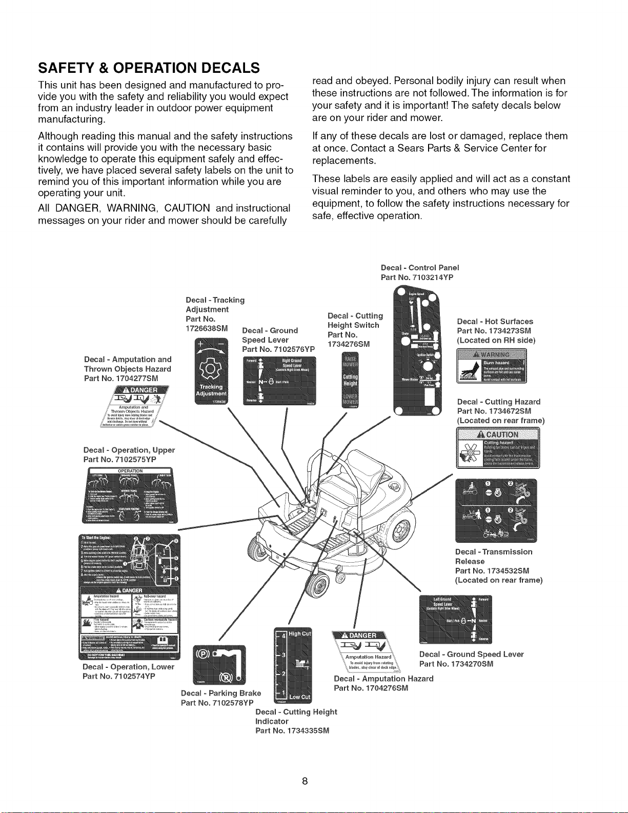
SAFETY & OPERATION DECALS
This unit has been designed and manufactured to pro-
vide you with the safety and reliability you would expect
from an industry leader in outdoor power equipment
manufacturing.
Although reading this manual and the safety instructions
it contains will provide you with the necessary basic
knowledge to operate this equipment safely and effec-
tively, we have placed several safety labels on the unit to
remind you of this important information while you are
operating your unit.
All DANGER, WARNING, CAUTION and instructional
messages on your rider and mower should be carefully
Decal =Tracking
Adjustment
Part No. Decam = Cutting
1726638SM Decal = Ground Height Switch
Speed Lever
Part No. 7102576YP
Decam= Amputation and
Thrown Objects Hazard
Part No. 1704277S&,1
read and obeyed. Personal bodily injury can result when
these instructions are not followed. The information is for
your safety and it is important! The safety decals below
are on your rider and mower.
If any of these decals are lost or damaged, replace them
at once. Contact a Sears Parts & Service Center for
replacements.
These labels are easily applied and will act as a constant
visual reminder to you, and others who may use the
equipment, to follow the safety instructions necessary for
safe, effective operation.
Decam = Control Panel
Part No. 7103214YP
Decal = Hot Surfaces
Part No.
1734276SM
Part No. 1734273SM
(Located on RH side)
Decal = Operation, Lower
Part No. 7102574YP
Detain =Cutting Hazard
Part No. 1734672SM
(Located on rear frame)
Decam=Transmission
Release
Part No. 1734532SM
(Located on rear frame)
DecaB =Ground Speed Lever
Part No. 1734270SM
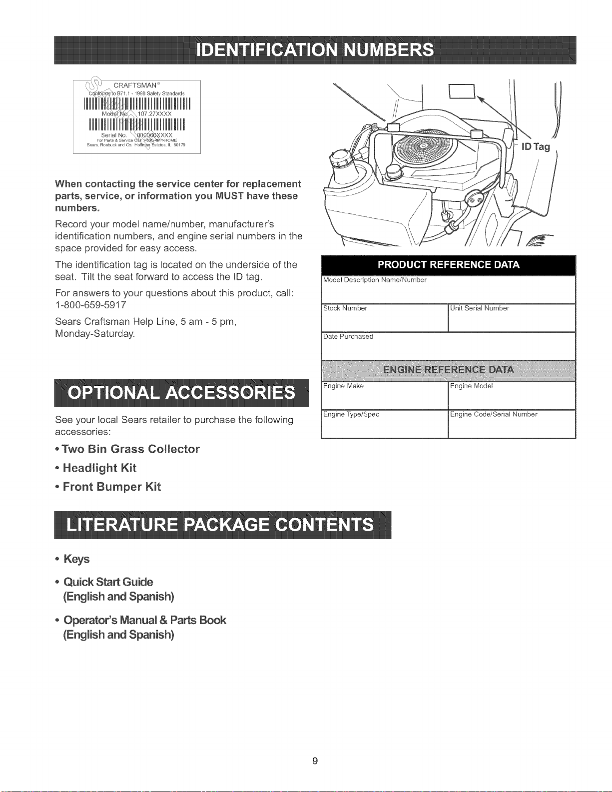
When contacting the service center for repmacement
parts, service, or information you MUST have these
numbers,
Record your model name/number, manufacturer's
identification numbers, and engine serial numbers in the
space provided for easy access.
The identification tag is located on the underside of the
seat. Tilt the seat forward to access the ID tag.
For answers to your questions about this product, call:
1-800-65%5917
Sears Craftsman Help Line, 5 am - 5 pm,
Monday-Saturday.
Model Description Name/Number
Stock Number Unit Serial Number
Date Purchased
Engine Make Engine Model
See your local Sears retailer to purchase the following
accessories:
°Two Bin Grass Collector
° Headlight Kit
° Front Bumper Kit
° Keys
° Quick Start Guide
(English and Spanish)
° Operator's Manuam & Parts Book
(English and Spanish)
Engine Type/Spec Engine Code/Serial Number
9
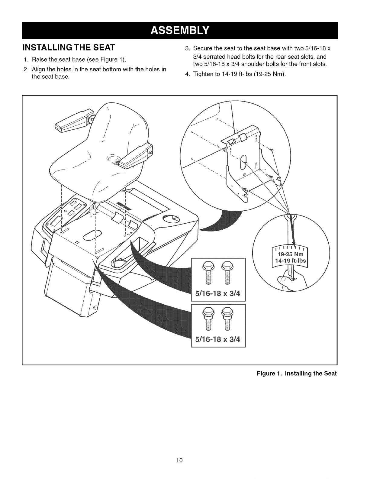
INSTALLING THE SEAT
1. Raise the seat base (see Figure 1).
2. Align the holes in the seat bottom with the holes in
the seat base.
I
I
I
I
I
I
3. Secure the seat to the seat base with two 5/16-18 x
3/4 serrated head bolts for the rear seat slots, and
two 5/16-18 x 3/4 shoulder bolts for the front slots.
4. Tighten to 14-19 ft-lbs (19-25 Nm).
I
I
19-25 Nm
14-19 ft-lbs
5/16-18 x 3/4
5/16-18 x 3/4
Figure 1. Installing the Seat
10
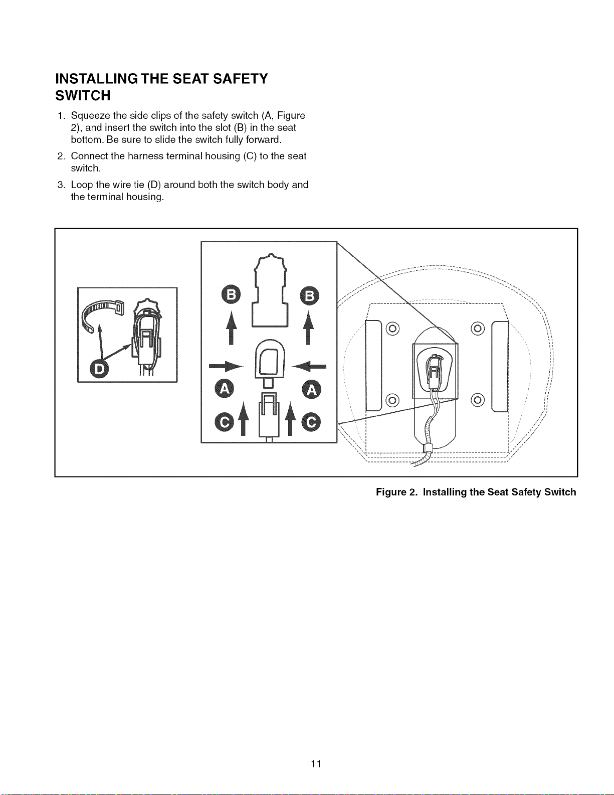
INSTALLING THE SEAT SAFETY
SWITCH
1. Squeeze the side clips of the safety switch (A, Figure
2), and insert the switch into the slot (B) in the seat
bottom. Be sure to slide the switch fully forward.
2. Connect the harness terminal housing (C) to the seat
switch.
,
Loop the wire tie (D) around both the switch body and
the terminal housing.
11
Figure 2. Installing the Seat Safety Switch
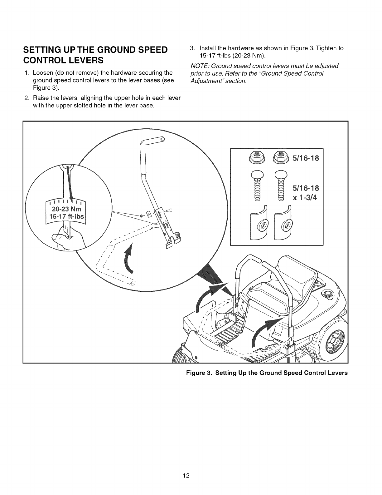
SETTING UP THE GROUND SPEED
CONTROL LEVERS
1. Loosen (do not remove) the hardware securing the
ground speed control levers to the lever bases (see
Figure 3).
2. Raise the levers, aligning the upper hole in each lever
with the upper slotted hole in the lever base.
20°23 Nm
15o17 ftqbs
3. Install the hardware as shown in Figure 3. Tighten to
15-17 ft-lbs (20-23 Nm).
NOTE: Ground speed control levers must be adjusted
prior to use. Refer to the "Ground Speed Control
Adjustment" section.
_ 5/16-18
_ 5/16-18
x 1-3/4
Figure 3. Setting Up the Ground Speed Control Levers
12
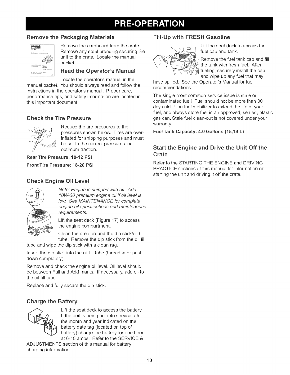
Remove the Packaging Materials
Remove the cardboard from the crate.
Remove any steel branding securing the
unit to the crate. Locate the manual
packet.
Read the Operator's Manuam
Locate the operator's manual in the
manual packet. You should always read and follow the
instructions in the operator's manual. Proper care,
performance tips, and safety information are located in
this important document.
Check the Tire Pressure
Reduce the tire pressures to the
pressures shown below. Tires are over-
inflated for shipping purposes and must
be set to the correct pressures for
optimum traction.
RearTire Pressure: 10-12 PSI
Front Tire Pressure: 18-20 PSI
Check Engine Oil Level
FiHoUp with FRESH Gasoline
Lift the seat deck to access the
__ fuel cap and tank.
have spilled. See the Operator's Manual for fuel
recommendations.
The single most common service issue is stale or
contaminated fuel! Fuel should not be more than 30
days old. Use fuel stabilizer to extend the life of your
fuel, and always store fuel in an approved, sealed, plastic
gas can. Stale fuel clean-out is not covered under your
warranty.
Fuel Tank Capacity: 4.0 Gallons (15,14 L)
Remove the fuel tank cap and fill
the tank with fresh fuel. After
fueling, securely install the cap
and wipe up any fuel that may
Start the Engine and Drive the Unit Off the
Crate
Refer to the STARTING THE ENGINE and DRIVING
PRACTICE sections of this manual for information on
starting the unit and driving it off the crate.
Note: Engine is shipped with oil. Add
10W-30 premium engine oil if off level is
low. See MAINTENANCE for complete
engine off specifications and maintenance
requirements.
Lift the seat deck (Figure 17) to access
the engine compartment.
Clean the area around the dip stick/oil fill
tube. Remove the dip stick from the oil fill
tube and wipe the dip stick with a clean rag.
Insert the dip stick into the oil fill tube (thread in or push
down completely).
Remove and check the engine oil level. Oil level should
be between Full and Add marks. If necessary, add oil to
the oil fill tube.
Replace and fully secure the dip stick.
Charge the Battery
Lift the seat deck to access the battery.
If the unit is being put into service after
the month and year indicated on the
battery date tag (located on top of
battery) charge the battery for one hour
at 6-10 amps. Refer to the SERVICE &
ADJUSTMENTS section of this manual for battery
charging information.
13
Parkin BrakeLever-
ENGAGEP0sit0n
Left
@ GroundSpeed
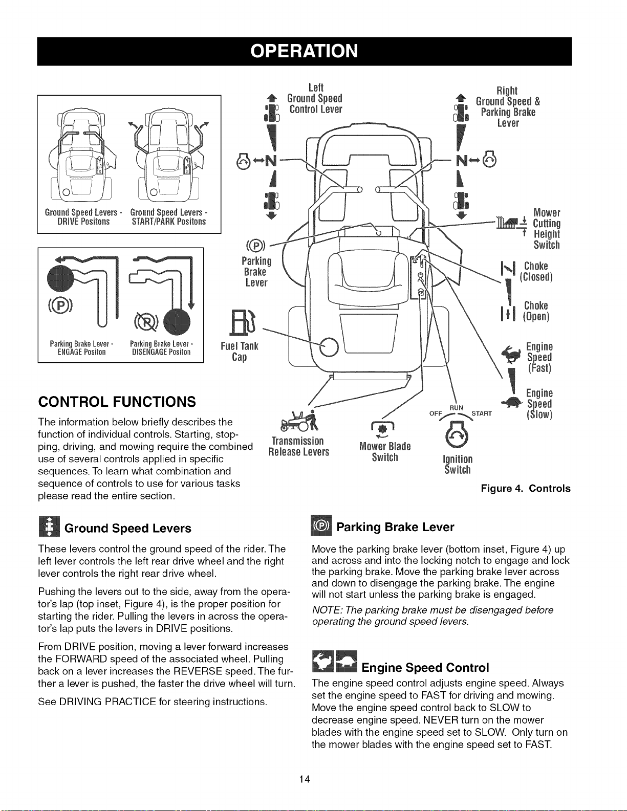
CONTROL FUNCTIONS
The information below briefly describes t
function of individual controls. Starting, stop- Transmission MowerBlade
ping, driving, and mowing require the combined ReleaseLevers
use of several controls applied in specific Switch
sequences. To learn what combination and
sequence of controls to use for various tasks
please read the entire section.
Ground Speed Levers
These levers control the ground speed of the rider. The
left lever controls the left rear drive wheel and the right
lever controls the right rear drive wheel.
Pushing the levers out to the side, away from the opera-
tor's lap (top inset, Figure 4), is the proper position for
starting the rider. Pulling the levers in across the opera-
tor's lap puts the levers in DRIVE positions.
From DRIVE position, moving a lever forward increases
the FORWARD speed of the associated wheel. Pulling
back on a lever increases the REVERSE speed. The fur-
ther a lever is pushed, the faster the drive wheel will turn.
See DRIVING PRACTICE for steering instructions.
Parking Brake Lever
Move the parking brake lever (bottom inset, Figure 4) up
and across and into the locking notch to engage and lock
the parking brake. Move the parking brake lever across
and down to disengage the parking brake. The engine
will not start unless the parking brake is engaged.
NOTE: The parking brake must be disengaged before
operating the ground speed levers.
__ Engine Speed Control
The engine speed control adjusts engine speed. Always
set the engine speed to FAST for driving and mowing.
Move the engine speed control back to SLOW to
decrease engine speed. NEVER turn on the mower
blades with the engine speed set to SLOW. Only turn on
the mower blades with the engine speed set to FAST.
Switch
Figure 4. Controls
14
Choke
CLOSE the choke for cold starting (pull knob up). OPEN
the choke once the engine starts (push knob down). If
the engine is warm, it may not require choking. If this is
the case, set the choke to OPEN (push the knob down)
while cranking the engine. In most cases, you will need
to close the choke in order to start the engine.
Mower Cutting Height Switch
To increase the mower cutting height (raise the mower
deck), press the top of the yellow cutting height switch.
To decrease mower cutting height (lower the mower
deck), press the bottom of the switch. Mower cutting
height range is approximately 3-3/4" to 1-1/2" (9,5 to 3,8
cm). The cutting height gauge indicates the position of
the mower deck. The cutting height gauge is located on
the front of the rider, just behind the driver's left leg.
Ignition Switch
The ignition switch starts and stops the engine; it has
three positions:
OFF Stops the engine and shuts off the
electrical system.
RUN Allows the engine to run and powers the
electrical system.
START Cranks the engine for starting.
NOTE: Never leave the ignition switch in the RUN posi-
tion with the engine stopped, This drains the battery.
Mower Blade Switch
The yellow mower blade switch turns the mower blades
on and off.To turn the mower blades ON, pull the switch
up. To turn the mower blades OFF, push the switch down.
Always set the engine speed control to FAST before turn-
ing the mower blades ON, and while mowing.
Transmission Release Levers
The transmission release levers deactivate the transmis-
sions so that the unit can be pushed by hand. See
PUSHING THE UNIT BY HAND for operational informa-
tion.
Fuel Tank
To remove the fuel tank cap, turn it counterclockwise.
GENERAL OPERATING SAFETY
Before first time operation:
• Be sure to read all information in the Safety and
Operation sections before attempting to operate this
rider and mower.
• Become familiar with all of the controls and how to
stop the unit.
• Drive in an open area without mowing to become
accustomed to driving the unit.
WARNING
If you do not understand how a specific control
functions, or have not yet thoroughly read the
CONTROL FUNCTIONS section, do so now.
Do NOT attempt to operate the rider without first
becoming familiar with the location and function
of ALL controls.
15
CHECKS BEFORE STARTING
• Check that the crankcase oil is filled to full mark on
dipstick.
• Fill the fuel tank with fresh fuel.
FUEL RECOMMENDATIONS
For daily operation: Use only unleaded gasoline with a
pump sticker octane rating of 87 or higher. Gasohol (up
to 10% ethyl alcohol, 90% unleaded gasoline by volume)
is approved as a fuel. Methyl Teriary Butyl Ether (MTBE)
and unleaded gasoline blends (up to a maximum of 15%
MTBE by volume) are approved as a fuel. No other gaso-
line/alcohol or gasoline/ether blends are approved. Do
not use fuel additives other than fuel stabilizer.
For storage: CAUTION: Alcohol blended fuels (called
gasohol or using ethanol or methanol) can attract mois-
ture which leads to separation and formation of acids
during storage. Acidic gas can damage the fuel system
of an engine while in storage.
To avoid engine problems always use fuel stabilizer,
especially before storage of 30 days or longer. Use fresh
fuel next season. See STORAGE instructions for addi-
tional information.
Never use engine or carburetor cleaner products in the
fuel tank or permanent damage may occur. To add fuel:
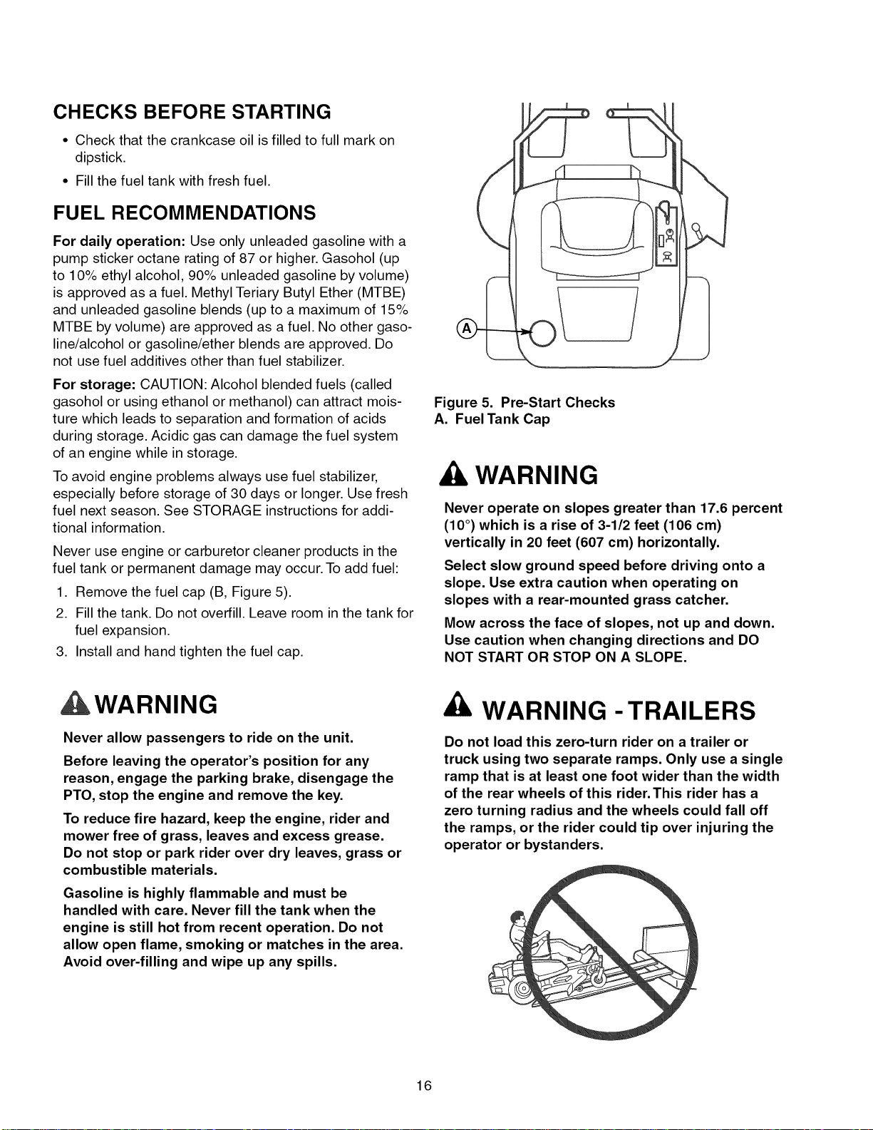
1. Remove the fuel cap (B, Figure 5).
2. Fill the tank. Do not overfill. Leave room in the tank for
fuel expansion.
3. Install and hand tighten the fuel cap.
J
Figure 5. Pre-Start Checks
A. Fuel Tank Cap
WARNING
Never operate on slopes greater than 17.6 percent
(10 °) which is a rise of 3-1/2 feet (106 cm)
vertically in 20 feet (607 cm) horizontally.
Select slow ground speed before driving onto a
slope. Use extra caution when operating on
slopes with a rear-mounted grass catcher.
Mow across the face of slopes, not up and down.
Use caution when changing directions and DO
NOT START OR STOP ON A SLOPE.
,WARNING
Never allow passengers to ride on the unit.
Before leaving the operator's position for any
reason, engage the parking brake, disengage the
PTO, stop the engine and remove the key.
To reduce fire hazard, keep the engine, rider and
mower free of grass, leaves and excess grease.
Do not stop or park rider over dry leaves, grass or
combustible materials.
Gasoline is highly flammable and must be
handled with care. Never fill the tank when the
engine is still hot from recent operation. Do not
allow open flame, smoking or matches in the area.
Avoid over-filling and wipe up any spills.
WARNING - TRAILERS
Do not load this zero-turn rider on a trailer or
truck using two separate ramps. Only use a single
ramp that is at least one foot wider than the width
of the rear wheels of this rider.This rider has a
zero turning radius and the wheels could fall off
the ramps, or the rider could tip over injuring the
operator or bystanders.
16
EMERGENCY STOPPING
In the event of an emergency the engine can be stopped
by simply turning the ignition switch to STOP. Use this
method only in emergency situations. For normal engine
shut down follow the procedure given in STOPPING THE
RIDER AND ENGINE.
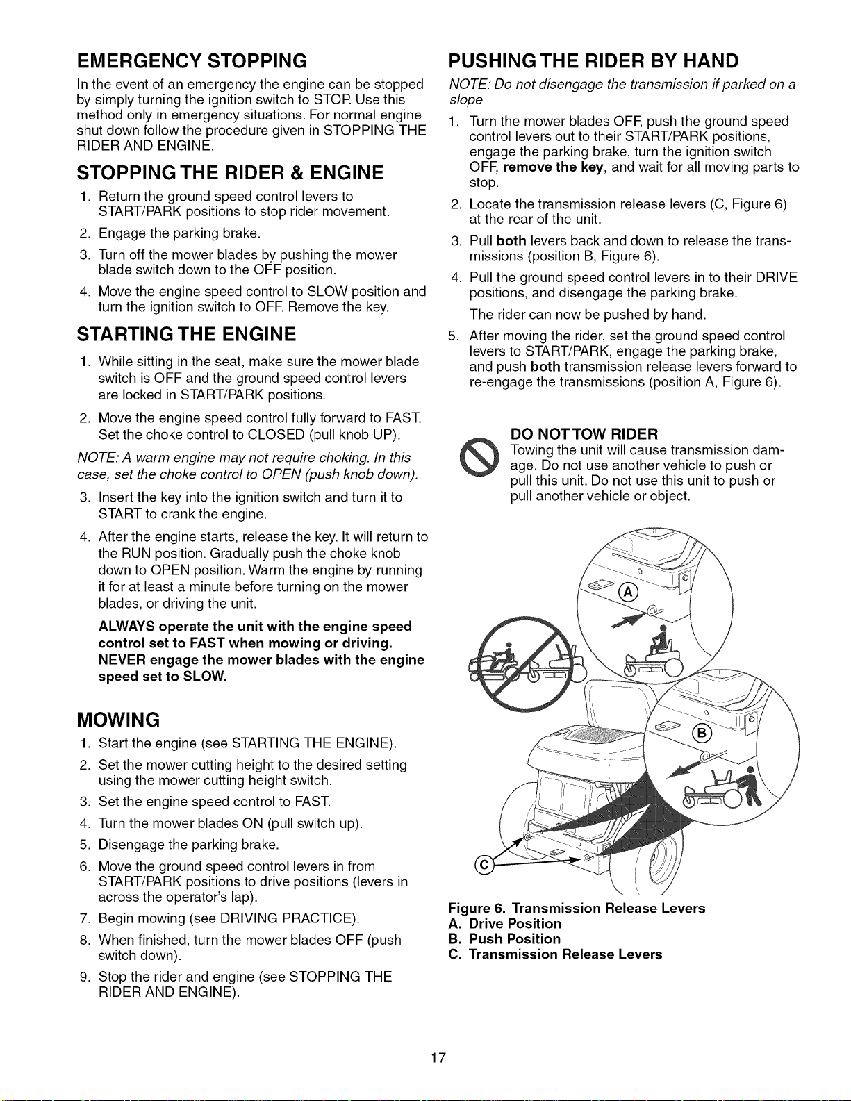
PUSHING THE RIDER BY HAND
NOTE: Do not disengage the transmission ff parked on a
slope
STOPPING THE RIDER & ENGINE
1. Return the ground speed control levers to
START/PARK positions to stop rider movement.
2. Engage the parking brake. 3.
3. Turn off the mower blades by pushing the mower
blade switch down to the OFF position. 4.
4. Move the engine speed control to SLOW position and
turn the ignition switch to OFE Remove the key.
2. Locate the transmission release levers (C, Figure 6)
STARTING THE ENGINE 5.
1. While sitting in the seat, make sure the mower blade
switch is OFF and the ground speed control levers
are locked in START/PARK positions.
2. Move the engine speed control fully forward to FAST.
Set the choke control to CLOSED (pull knob UP).
NOTE: A warm engine may not require choking, In this
case, set the choke control to OPEN (push knob down),
3. Insert the key into the ignition switch and turn it to
START to crank the engine.
4. After the engine starts, release the key. It will return to
the RUN position. Gradually push the choke knob
down to OPEN position. Warm the engine by running
it for at least a minute before turning on the mower
blades, or driving the unit.
ALWAYS operate the unit with the engine speed
control set to FAST when mowing or driving.
NEVER engage the mower blades with the engine
speed set to SLOW.
,
Turn the mower blades OFF, push the ground speed
control levers out to their START/PARK positions,
engage the parking brake, turn the ignition switch
OFF, remove the key, and wait for all moving parts to
stop.
at the rear of the unit.
Pull both levers back and down to release the trans-
missions (position B, Figure 6).
Pull the ground speed control levers in to their DRIVE
positions, and disengage the parking brake.
The rider can now be pushed by hand.
After moving the rider, set the ground speed control
levers to START/PARK, engage the parking brake,
and push both transmission release levers forward to
re-engage the transmissions (position A, Figure 6).
DO NOTTOW RIDER
Towing the unit will cause transmission dam-
age. Do not use another vehicle to push or
pull this unit. Do not use this unit to push or
pull another vehicle or object.
MOWING
1. Start the engine (see STARTING THE ENGINE).
2. Set the mower cutting height to the desired setting
using the mower cutting height switch.
3. Set the engine speed control to FAST.
4. Turn the mower blades ON (pull switch up).
5. Disengage the parking brake.
6. Move the ground speed control levers in from
START/PARK positions to drive positions (levers in
across the operator's lap).
7. Begin mowing (see DRIVING PRACTICE).
8. When finished, turn the mower blades OFF (push
switch down).
9. Stop the rider and engine (see STOPPING THE
RIDER AND ENGINE).
Figure 6. Transmission Release Levers
A. Drive Position
B. Push Position
C. Transmission Release Levers
17
DRIVING PRACTICE -
BA SiC DRIVING
WARNING: Never operate on slopes greater than 17.6%
(10°). See SLOPE OPERATION in the safety section.
Zero turn riders operate differently from other four-
wheeled vehicles. The drive wheels are also your steer-
ing wheels. If you cannot drive the unit on a hill, you will
not be able to steer the unit on it. Operating zero turn
units on slopes requires extra caution.
The lever controls of the zero turn rider are very respon-
sive, and learning to gain a smooth and efficient control
of the rider's forward, reverse, and turning movements
will take some practice.
Spend some time going through the following maneuvers
and becoming familiar with how the unit accelerates,
travels, and steers - before you begin mowing - is
absolutely essential to getting the most out of the zero
turn rider.
Locate a smooth, flat area of your lawn - one with
plenty of room to maneuver. (Clear the area of objects,
people and animals before you begin.) Operate the unit
at mid-throttle during this practice session (ALWAYS
operate at full throttle when mowing), and turn slowly to
prevent tire slippage and damage to your lawn.
We suggest you begin with the Smooth Travel procedure
to the right, and then advance through the forward,
reverse, and turning maneuvers.
WARNING
Do not mow in reverse unless absolutely
necessary. Always look down and behind before
and while travelling in reverse.
Forward Travel
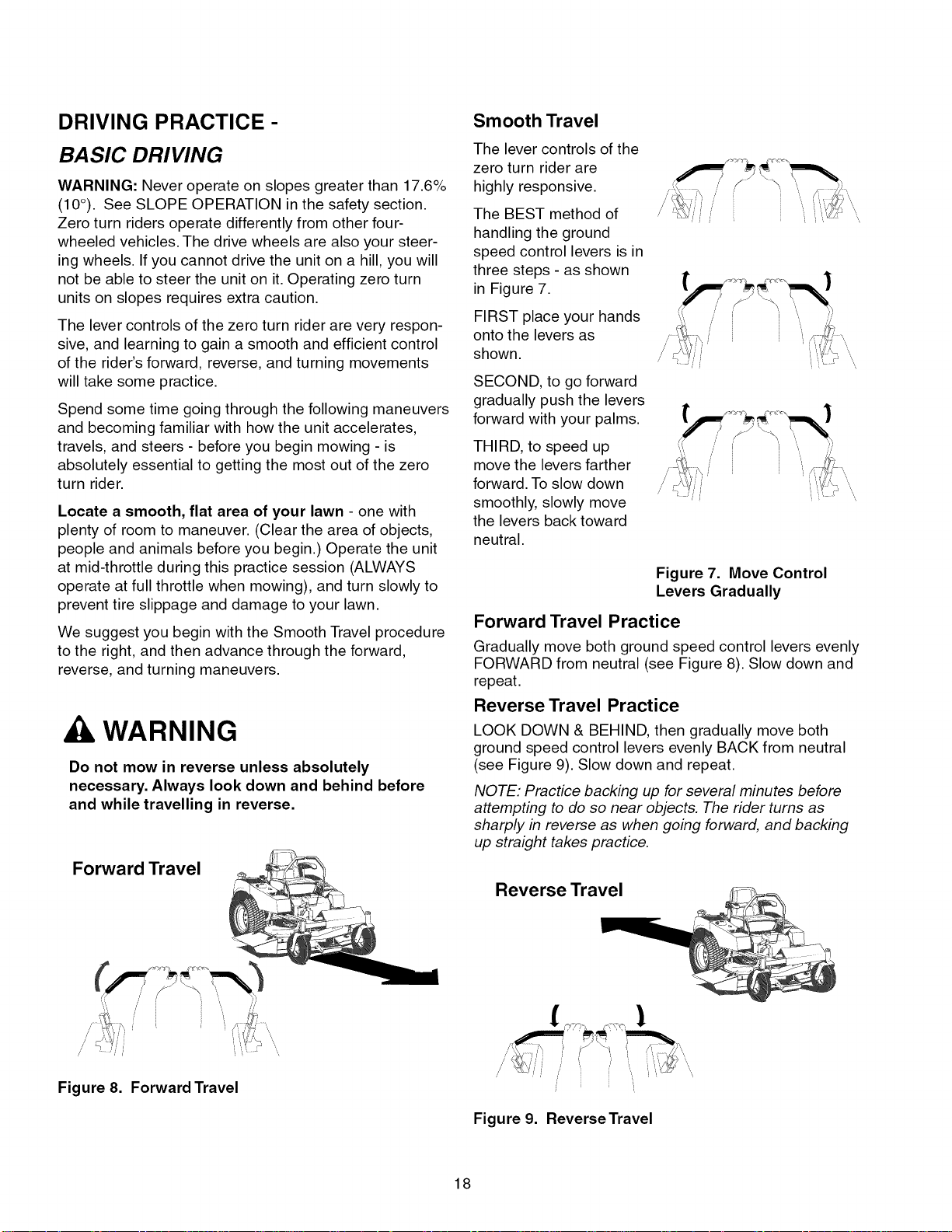
Smooth Travel
The lever controls of the
zero turn rider are
highly responsive.
The BEST method of
handling the ground
speed control levers is in
three steps - as shown
in Figure 7.
FIRST place your hands
onto the levers as
shown.
SECOND, to go forward
gradually push the levers
forward with your palms.
THIRD, to speed up
move the levers farther
forward. To slow down
smoothly, slowly move
the levers back toward
neutral.
Figure 7. Move Control
Levers Gradually
Forward Travel Practice
Gradually move both ground speed control levers evenly
FORWARD from neutral (see Figure 8). Slow down and
repeat.
Reverse Travel Practice
LOOK DOWN & BEHIND, then gradually move both
ground speed control levers evenly BACK from neutral
(see Figure 9). Slow down and repeat.
NOTE: Practice backing up for several minutes before
attempting to do so near objects. The rider turns as
sharply in reverse as when going forward, and backing
up straight takes practice.
Reverse Travel
Figure 8. Forward Travel
!i
Figure 9. Reverse Travel
18
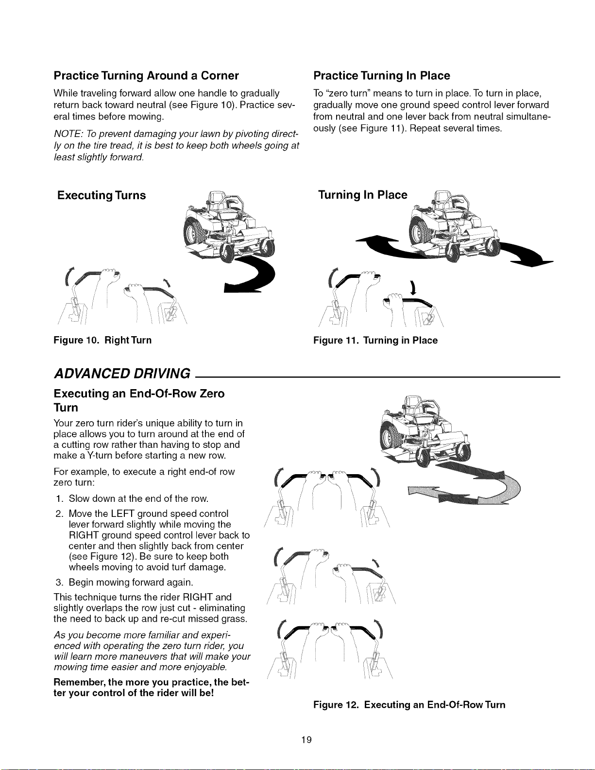
Practice Turning Around a Corner
While traveling forward allow one handle to gradually
return back toward neutral (see Figure 10). Practice sev-
eral times before mowing.
NOTE: To prevent damaging your lawn by pivoting direct-
ly on the tire tread, it is best to keep both wheels going at
least slightly forward.
Practice Turning In Place
To "zero turn" means to turn in place. To turn in place,
gradually move one ground speed control lever forward
from neutral and one lever back from neutral simultane-
ously (see Figure 11). Repeat several times.
Executing Turns
Figure 10. RightTurn
ADVANCED DRIVING
Executing an End-Of-Row Zero
Turn
Your zero turn rider's unique ability to turn in
place allows you to turn around at the end of
a cutting row rather than having to stop and
make a Y-turn before starting a new row.
For example, to execute a right end-of row
zero turn:
,
Slow down at the end of the row.
2.
Move the LEFT ground speed control
lever forward slightly while moving the
RIGHT ground speed control lever back to
center and then slightly back from center
(see Figure 12). Be sure to keep both
wheels moving to avoid turf damage.
3. Begin mowing forward again.
This technique turns the rider RIGHT and
slightly overlaps the row just cut - eliminating
the need to back up and re-cut missed grass.
As you become more familiar and experi-
enced with operating the zero turn rider, you
will learn more maneuvers that will make your
mowing time easier and more enjoyable.
Remember, the more you practice, the bet-
ter your control of the rider will be!
Turning In Place
/
Figure 11. Turning in Place
///
[
Figure 12. Executing an End-Of-Row Turn
19
MOWER DECK REMOVAL &
INSTALLATION
NOTE: Perform mower removal and installation on a
hard, level surface such as a concrete floor.
WARNING
After lowering the mower cutting height, engage
parking brake, turn off the mower blades, turn the
ignition switch to STOP, and remove key before
attempting to install or remove the mower.
Removing the Mower Deck
1. Turn the mower blades OFF, put the ground speed
control levers in START/PARK position, turn the igni-
tion OFF, and wait for all moving parts to stop.
2. Pivot the front wheels forward.
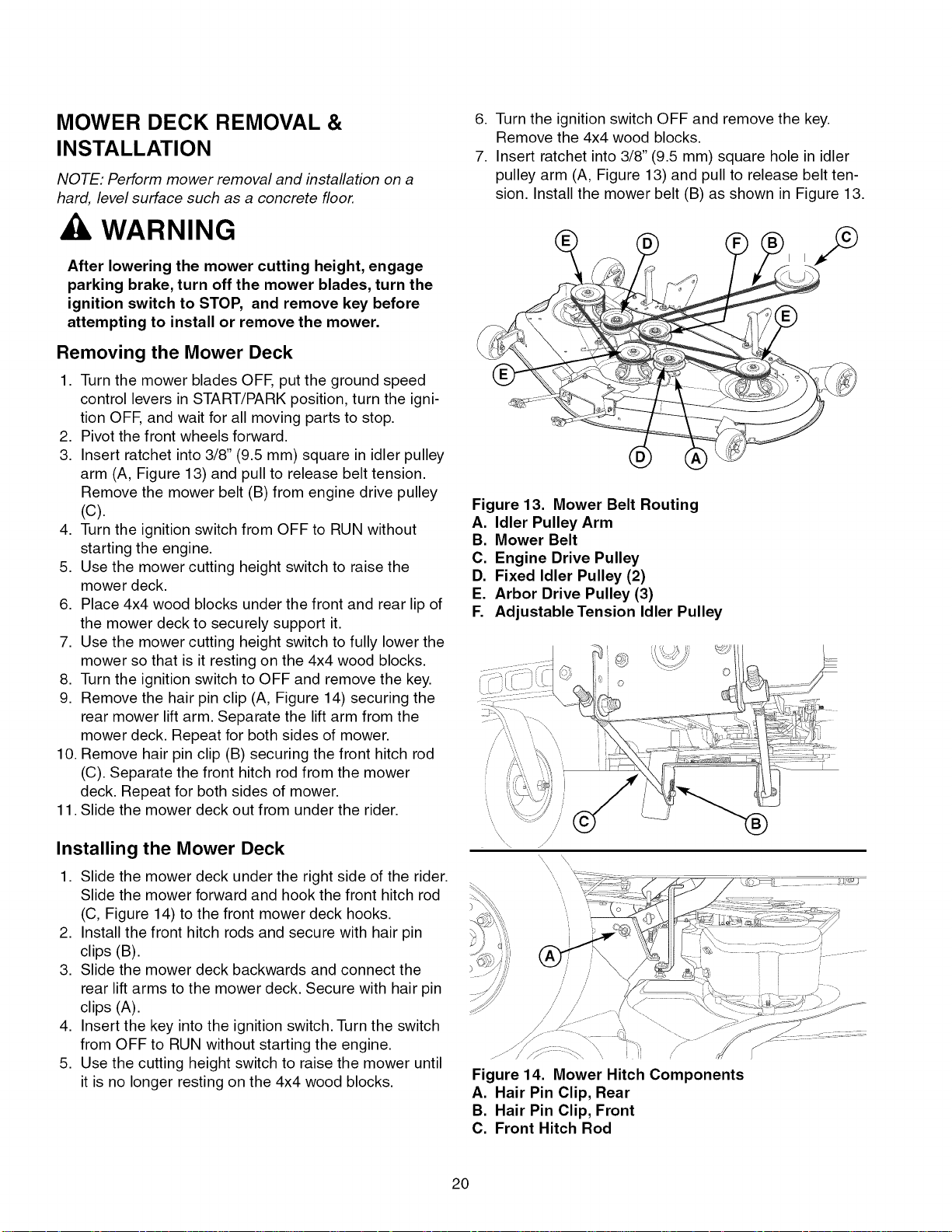
3. Insert ratchet into 3/8" (9.5 mm) square in idler pulley
arm (A, Figure 13) and pull to release belt tension.
Remove the mower belt (B) from engine drive pulley
(C).
4. Turn the ignition switch from OFF to RUN without
starting the engine.
5. Use the mower cutting height switch to raise the
mower deck.
6. Place 4x4 wood blocks under the front and rear lip of
the mower deck to securely support it.
7. Use the mower cutting height switch to fully lower the
mower so that is it resting on the 4x4 wood blocks.
8. Turn the ignition switch to OFF and remove the key.
9. Remove the hair pin clip (A, Figure 14) securing the
rear mower lift arm. Separate the lift arm from the
mower deck. Repeat for both sides of mower.
10. Remove hair pin clip (B) securing the front hitch rod
(C). Separate the front hitch rod from the mower
deck. Repeat for both sides of mower.
11. Slide the mower deck out from under the rider.
6. Turn the ignition switch OFF and remove the key.
Remove the 4x4 wood blocks.
7. Insert ratchet into 3/8" (9.5 mm) square hole in idler
pulley arm (A, Figure 13) and pull to release belt ten-
sion. Install the mower belt (B) as shown in Figure 13.
Figure 13. Mower Belt Routing
A. Idler Pulley Arm
B. Mower Belt
C. Engine Drive Pulley
D. Fixed Idler Pulley (2)
E. Arbor Drive Pulley (3)
F. Adjustable Tension Idler Pulley
Installing the Mower Deck
1. Slide the mower deck under the right side of the rider.
Slide the mower forward and hook the front hitch rod
(C, Figure 14) to the front mower deck hooks.
2. Install the front hitch rods and secure with hair pin
clips (B).
3. Slide the mower deck backwards and connect the
rear lift arms to the mower deck. Secure with hair pin
clips (A).
4. Insert the key into the ignition switch. Turn the switch
from OFF to RUN without starting the engine.
5. Use the cutting height switch to raise the mower until
it is no longer resting on the 4x4 wood blocks.
/ /
// /
// //
/
Figure 14. Mower Hitch Components
A. Hair Pin Clip, Rear
B. Hair Pin Clip, Front
C. Front Hitch Rod
20
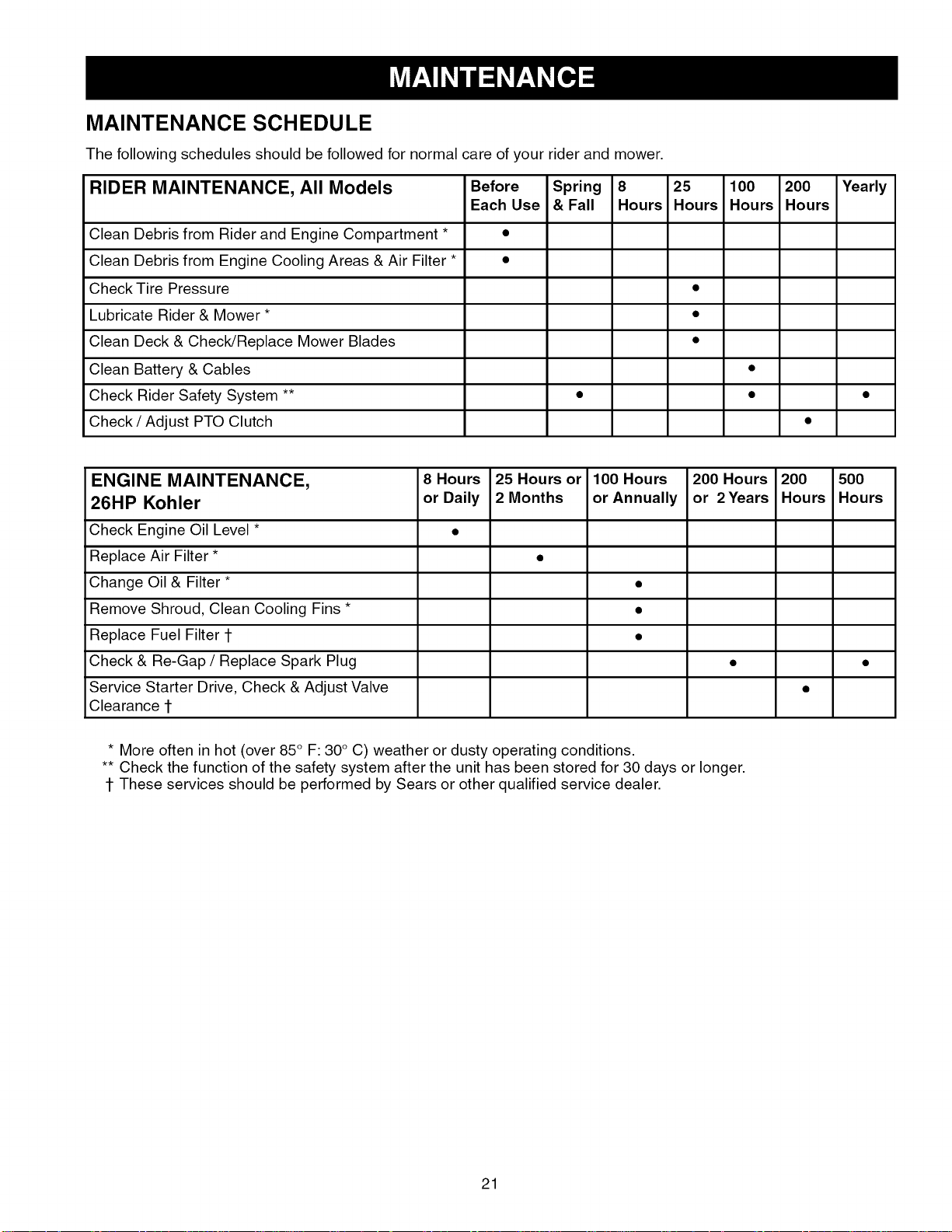
MAINTENANCE SCHEDULE
The following schedules should be followed for normal care of your rider and mower.
RIDER MAINTENANCE, All Models Before Spring 8 25 100 200 Yearly
Each Use & Fall Hours Hours Hours Hours
Clean Debris from Rider and Engine Compartment * •
Clean Debris from Engine Cooling Areas & Air Filter * •
Check Tire Pressure •
Lubricate Rider & Mower * •
Clean Deck & Check/Replace Mower Blades •
Clean Battery & Cables •
Check Rider Safety System ** • • •
Check / Adjust PTO Clutch •
ENGINE MAINTENANCE, 8 Hours 25 Hours or 100 Hours 200 Hours 200 500
26HP Kohler orDaily 2Months orAnnually or 2Years Hours Hours
Check Engine Oil Level * •
Replace Air Filter * •
Change Oil & Filter * •
Remove Shroud, Clean Cooling Fins * •
Replace Fuel Filter 1- •
Check & Re-Gap / Replace Spark Plug • •
Service Starter Drive, Check & Adjust Valve •
Clearance 1-
* More often in hot (over 85° F: 30° C) weather or dusty operating conditions.
** Check the function of the safety system after the unit has been stored for 30 days or longer.
1-These services should be performed by Sears or other qualified service dealer.
21
Rider Maintenance Items
WARNING
Move the ground speed levers to START/PARK
positions, engage the parking brake, turn the
mower blades OFF, turn the ignition switch OFF,
and wait for all moving parts to stop before
accessing the engine compartment or performing
any maintenance procedures.
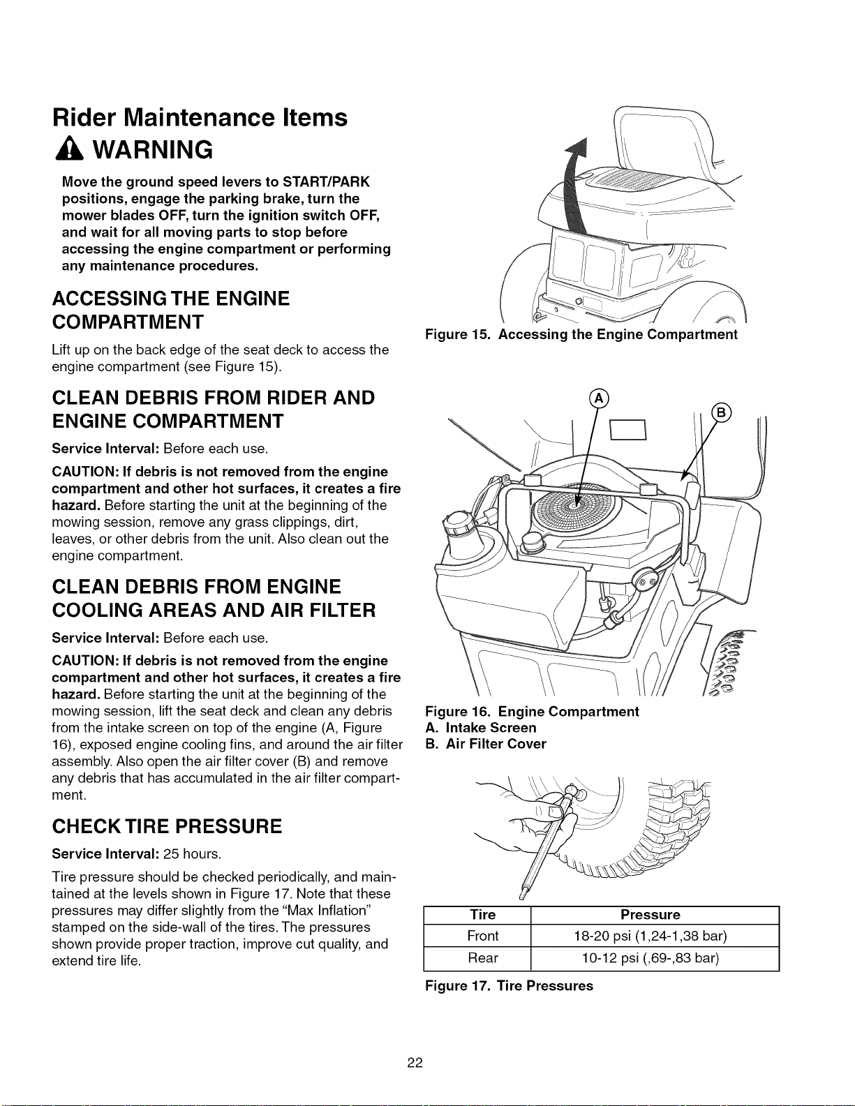
ACCESSING THE ENGINE
COMPARTMENT
Lift up on the back edge of the seat deck to access the
engine compartment (see Figure 15).
CLEAN DEBRIS FROM RIDER AND
ENGINE COMPARTMENT
Service Interval: Before each use.
CAUTION: If debris is not removed from the engine
compartment and other hot surfaces, it creates a fire
hazard. Before starting the unit at the beginning of the
mowing session, remove any grass clippings, dirt,
leaves, or other debris from the unit. Also clean out the
engine compartment.
Figure 15. Accessing the Engine Compartment
\
\
!
CLEAN DEBRIS FROM ENGINE
COOLING AREAS AND AIR FILTER
Service Interval: Before each use.
CAUTION: If debris is not removed from the engine
compartment and other hot surfaces, it creates a fire
hazard. Before starting the unit at the beginning of the
mowing session, lift the seat deck and clean any debris
from the intake screen on top of the engine (A, Figure
16), exposed engine cooling fins, and around the air filter
assembly. Also open the air filter cover (B) and remove
any debris that has accumulated in the air filter compart-
ment.
CHECK TIRE PRESSURE
Service Interval: 25 hours.
Tire pressure should be checked periodically, and main-
tained at the levels shown in Figure 17. Note that these
pressures may differ slightly from the "Max Inflation"
stamped on the side-wall of the tires. The pressures
shown provide proper traction, improve cut quality, and
extend tire life.
Figure 16. Engine Compartment
A. Intake Screen
B. Air Filter Cover
Tire Pressure
Front 18-20 psi (1,24-1,38 bar)
Rear 10-12 psi (,69-,83 bar)
Figure 17. Tire Pressures
22
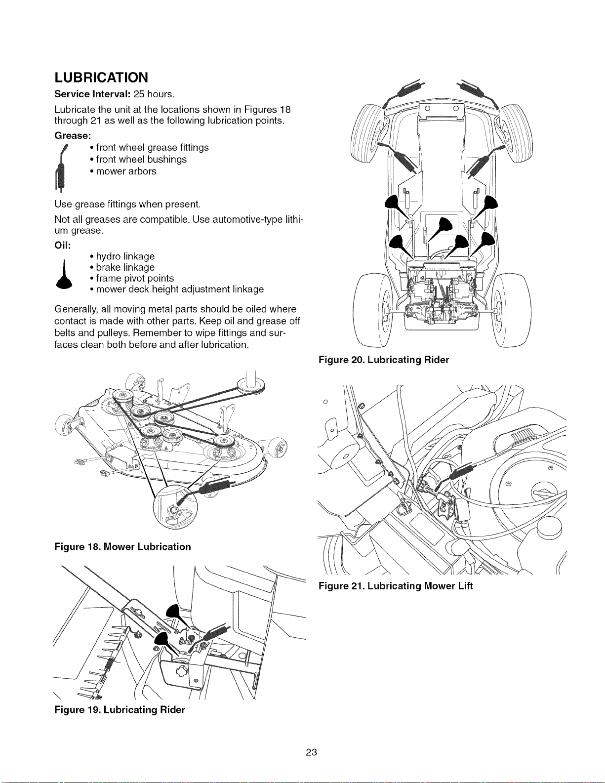
LUBRICATION
Service Interval: 25 hours.
Lubricate the unit at the locations shown in Figures 18
through 21 as well as the following lubrication points.
Grease:
• front wheel grease fittings
• front wheel bushings
• mower arbors
Use grease fittings when present.
Not all greases are compatible. Use automotive-type lithi-
um grease.
Oil:
• hydro linkage
• brake linkage
• frame pivot points
• mower deck height adjustment linkage
Generally, all moving metal parts should be oiled where
contact is made with other parts. Keep oil and grease off
belts and pulleys. Remember to wipe fittings and sur-
faces clean both before and after lubrication.
Figure 20. Lubricating Rider
Figure 18. Mower Lubrication
\
\
Figure 19. Lubricating Rider
Figure 21. Lubricating Mower Lift
23
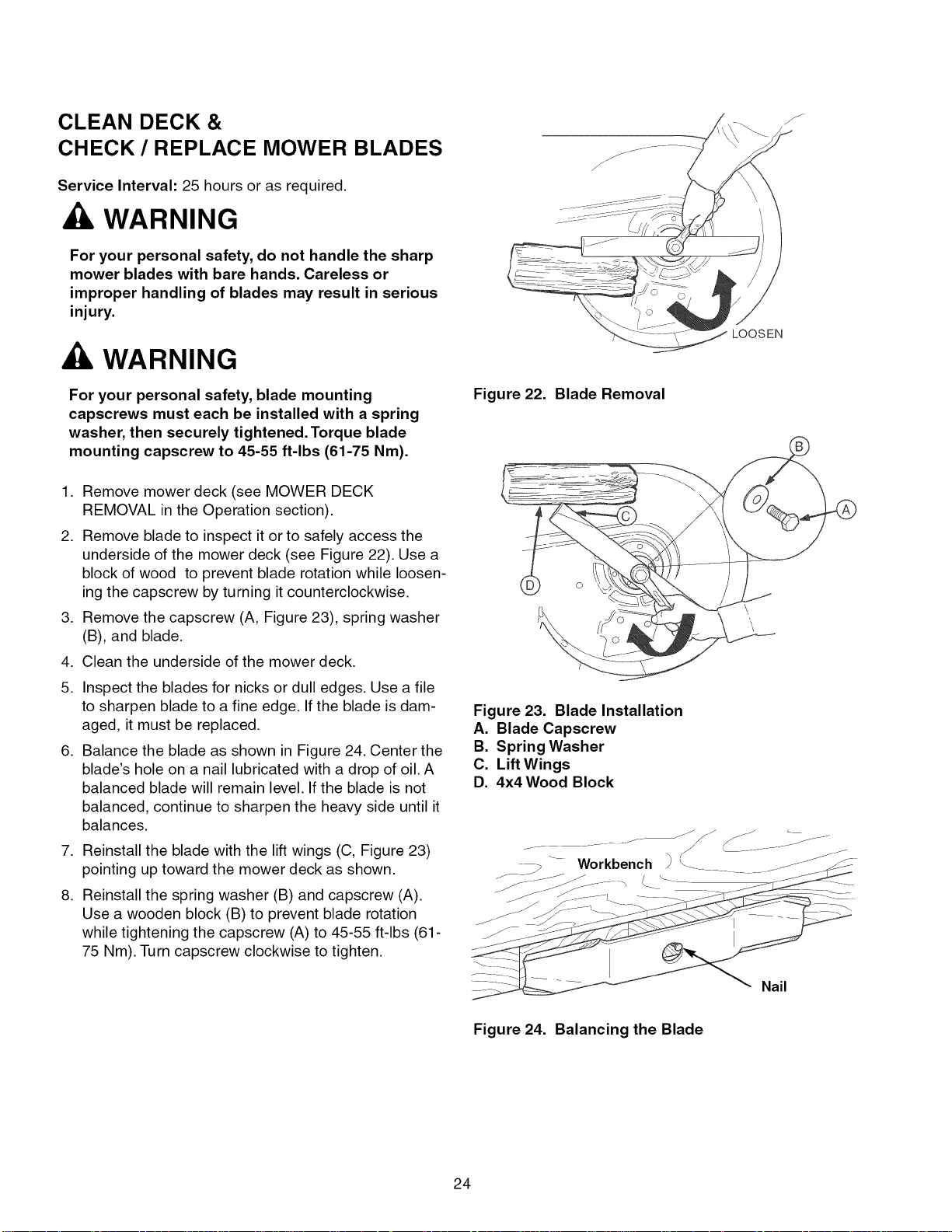
CLEAN DECK &
CHECK/REPLACE MOWER BLADES
Service Interval: 25 hours or as required.
WARNING
For your personal safety, do not handle the sharp
mower blades with bare hands. Careless or
improper handling of blades may result in serious
injury.
WARNING
LOOSEN
For your personal safety, blade mounting
capscrews must each be installed with a spring
washer, then securely tightened. Torque blade
mounting capscrew to 45-55 ft-lbs (61-75 Nm).
1. Remove mower deck (see MOWER DECK
REMOVAL in the Operation section).
2. Remove blade to inspect it or to safely access the
underside of the mower deck (see Figure 22). Use a
block of wood to prevent blade rotation while loosen-
ing the capscrew by turning it counterclockwise.
3. Remove the capscrew (A, Figure 23), spring washer
(B), and blade.
4. Clean the underside of the mower deck.
5. Inspect the blades for nicks or dull edges. Use a file
to sharpen blade to a fine edge. If the blade is dam-
aged, it must be replaced.
6. Balance the blade as shown in Figure 24. Center the
blade's hole on a nail lubricated with a drop of oil. A
balanced blade will remain level. If the blade is not
balanced, continue to sharpen the heavy side until it
balances.
7. Reinstall the blade with the lift wings (C, Figure 23)
pointing up toward the mower deck as shown.
8. Reinstall the spring washer (B) and capscrew (A).
Use a wooden block (B) to prevent blade rotation
while tightening the capscrew (A) to 45-55 ft-lbs (61-
75 Nm). Turn capscrew clockwise to tighten.
Figure 22. Blade Removal
Figure 23. Blade Installation
A. Blade Capscrew
B. Spring Washer
C. Lift Wings
D. 4x4Wood Block
Figure 24. Balancing the Blade
24
Nail
CLEANING THE BATTERY AND
CABLES
WARNING
CHECK RIDER SAFETY
SYSTEM
Corrosion hazard.
Batteries contain acid. Always keep the
battery upright and do not spill the
electrolyte. Avoid contact with skin and
eyes.
Explosion hazard.
Changing the battery produces explosive
hydrogen gas. Only charge the battery in a
well ventilated area, away from any ignition
source such as a water heater, electric
motor, or a lit cigarette.
Wear Protective Equipment
Always wear gloves and safety glasses
when handling the battery and battery
cables.
Service Interval: 100 hours.
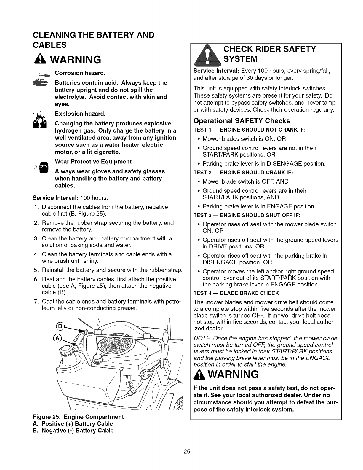
.
Disconnect the cables from the battery, negative
cable first (B, Figure 25).
2.
Remove the rubber strap securing the battery, and
remove the battery.
3.
Clean the battery and battery compartment with a
solution of baking soda and water.
4.
Clean the battery terminals and cable ends with a
wire brush until shiny.
5.
Reinstall the battery and secure with the rubber strap.
6.
Reattach the battery cables: first attach the positive
cable (see A, Figure 25), then attach the negative
cable (B).
.
Coat the cable ends and battery terminals with petro-
leum jelly or non-conducting grease.
Service Interval: Every 100 hours, every spring/fall,
and after storage of 30 days or longer.
This unit is equipped with safety interlock switches.
These safety systems are present for your safety. Do
not attempt to bypass safety switches, and never tamp-
er with safety devices. Check their operation regularly.
Operational SAFETY Checks
TEST 1 -- ENGINESHOULD NOTCRANK IF:
• Mower blades switch is ON, OR
• Ground speed control levers are not in their
START/PARK positions, OR
• Parking brake lever is in DISENGAGE position.
TEST 2 -- ENGINESHOULD CRANK IF:
• Mower blade switch is OFE AND
• Ground speed control levers are in their
START/PARK positions, AND
• Parking brake lever is in ENGAGE position.
TEST 3 -- ENGINESHOULD SHUT OFF IF:
• Operator rises off seat with the mower blade switch
ON, OR
• Operator rises off seat with the ground speed levers
in DRIVE positions, OR
• Operator rises off seat with the parking brake in
DISENGAGE position, OR
• Operator moves the left and/or right ground speed
control lever out of its START/PARK position with
the parking brake lever in ENGAGE position.
TEST 4 -- BLADE BRAKE CHECK
The mower blades and mower drive belt should come
to a complete stop within five seconds after the mower
blade switch is turned OFE If mower drive belt does
not stop within five seconds, contact your local author-
ized dealer.
Figure 25. Engine Compartment
A. Positive (+) Battery Cable
B. Negative (-) Battery Cable
NOTE: Once the engine has stopped, the mower blade
switch must be turned OFF, the ground speed control
levers must be locked in their START/PARK positions,
and the parking brake lever must be in the ENGAGE
position in order to start the engine.
WARNING
If the unit does not pass a safety test, do not oper-
ate it. See your local authorized dealer. Under no
circumstance should you attempt to defeat the pur-
pose of the safety interlock system.
25
CHECK / ADJUST PTO CLUTCH
WARNING
To avoid serious injury, perform adjustments only
with engine stopped, key removed and tractor on
level ground.
Service Interval: 200 hours.
The Power Take Off (PTO) clutch drives the mower
blades. The PTO clutch is engaged and disengaged by
the mower blade switch. Check the PTO clutch adjust-
ment every 200 hours of operation. Also perform the fol-
lowing procedure if the clutch is slipping, will not engage,
or if a new clutch has been installed.
1. Remove key from ignition switch and disconnect
spark plug wires to prevent the possibility of acciden-
tal starting while the PTO is being adjusted.
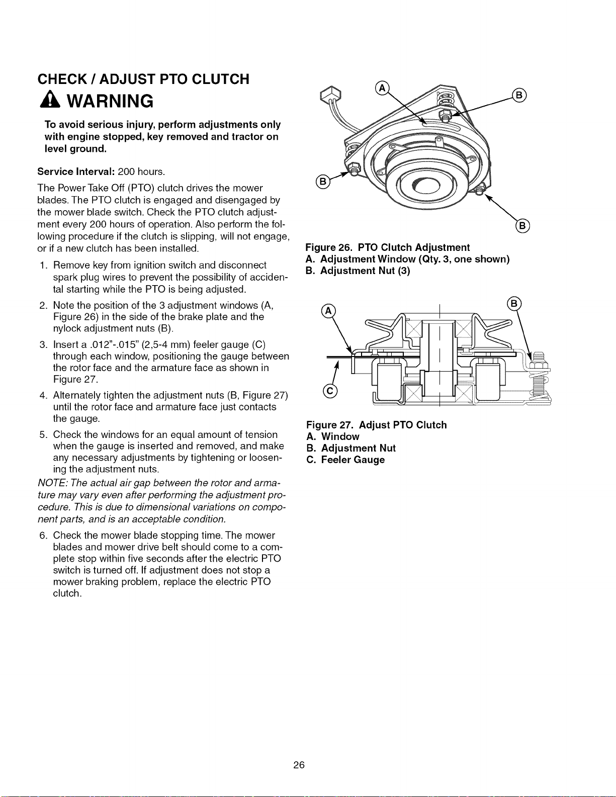
2. Note the position of the 3 adjustment windows (A,
Figure 26) in the side of the brake plate and the
nylock adjustment nuts (B).
3. Insert a .012"-.015" (2,5-4 mm) feeler gauge (C)
through each window, positioning the gauge between
the rotor face and the armature face as shown in
Figure 27.
4. Alternately tighten the adjustment nuts (B, Figure 27)
until the rotor face and armature face just contacts
the gauge.
5. Check the windows for an equal amount of tension
when the gauge is inserted and removed, and make
any necessary adjustments by tightening or loosen-
ing the adjustment nuts.
NOTE: The actual air gap between the rotor and arma-
ture may vary even after performing the adjustment pro-
cedure. This is due to dimensional variations on compo-
nent parts, and is an acceptable condition.
6. Check the mower blade stopping time. The mower
blades and mower drive belt should come to a com-
plete stop within five seconds after the electric PTO
switch is turned off. If adjustment does not stop a
mower braking problem, replace the electric PTO
clutch.
Figure 26. PTO Clutch Adjustment
A. Adjustment Window (Qty. 3, one shown)
B. Adjustment Nut (3)
Figure 27. Adjust PTO Clutch
A. Window
B. Adjustment Nut
C. Feeler Gauge
26
Engine Maintenance Items
CHECK ENGINE OIL LEVEL
Service Interval: Before each use, and every 8 hours.
1. Turn the engine off, and set the ground speed con-
trols to PARK. Park on a level surface. Allow the
engine to cool.
2. Clean the area around the dip stick (C, Figure 29).
3. Remove the dip stick (C) and clean it with a paper
towel.
.
Insert the dip stick back into the engine, and push
firmly into place.
.
Remove the dip stick and read the oil level. The oil
level should be between the "F" and "1" marks (D). If
not, add oil according to the oil recommendations
chart (see Figure 28).
CHANGE ENGINE OIL & FILTER
Service Interval: 100 hours.
NOTE: Change engine oil while the engine is warm. Run
the engine for a few minutes, then shut the engine off
and allow it to cool.
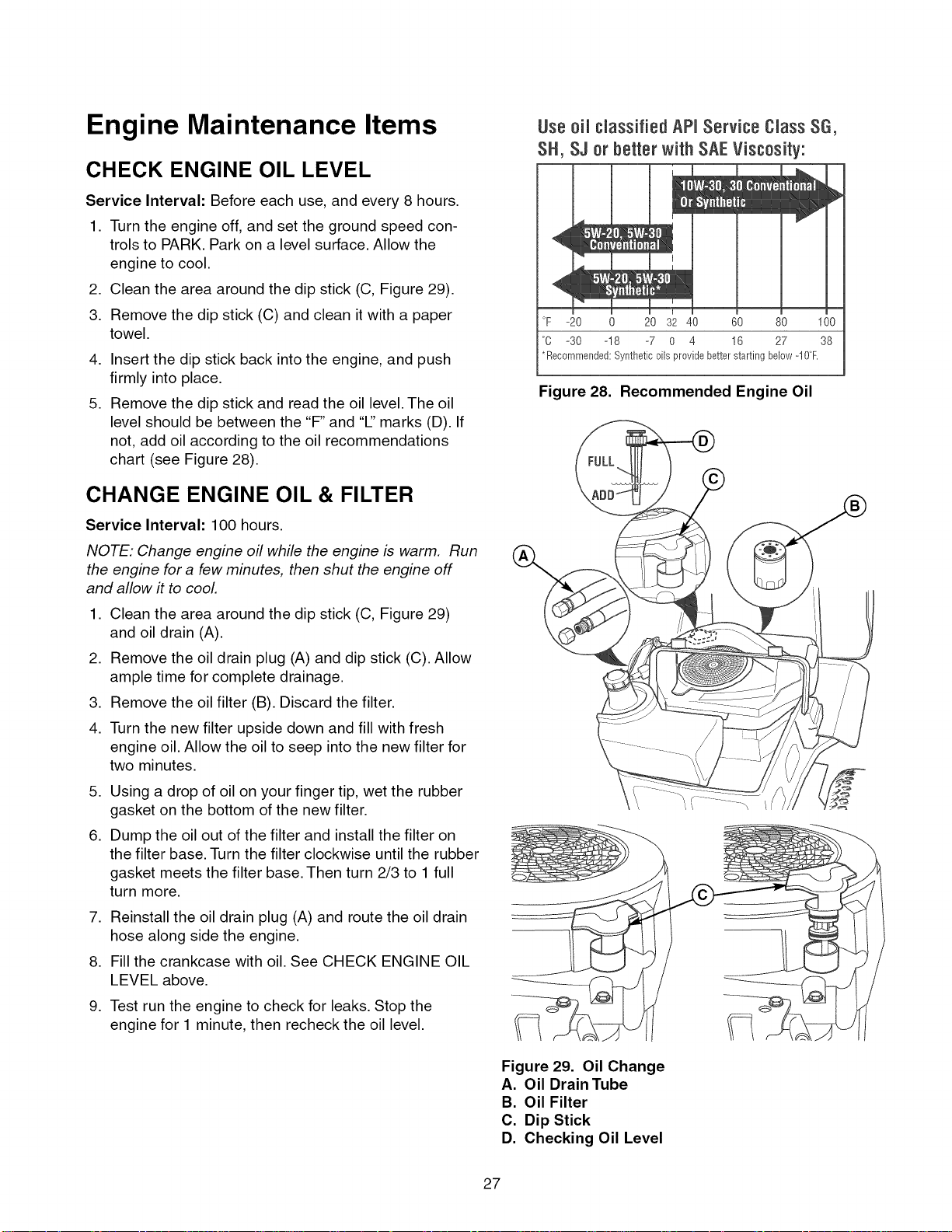
Use 0il classified APMService Class SG,
SH, SJ 0r better with SAEViscosity:
°F =20 20 32 40 60 80 100
°O =30 o18 =7 0 4 16 27 38
*Recommended: Synthetic oils provide better starting below-IOF.
Figure 28. Recommended Engine Oil
1. Clean the area around the dip stick (C, Figure 29)
and oil drain (A).
2. Remove the oil drain plug (A) and dip stick (C). Allow
ample time for complete drainage.
3. Remove the oil filter (B). Discard the filter.
4. Turn the new filter upside down and fill with fresh
engine oil. Allow the oil to seep into the new filter for
two minutes.
.
Using a drop of oil on your finger tip, wet the rubber
gasket on the bottom of the new filter.
.
Dump the oil out of the filter and install the filter on
the filter base. Turn the filter clockwise until the rubber
gasket meets the filter base. Then turn 2/3 to 1 full
turn more.
7. Reinstall the oil drain plug (A) and route the oil drain
hose along side the engine.
8. Fill the crankcase with oil. See CHECK ENGINE OIL
LEVEL above.
9. Test run the engine to check for leaks. Stop the
engine for 1 minute, then recheck the oil level.
Figure 29. Oil Change
A. Oil Drain Tube
B. Oil Filter
C. Dip Stick
D. Checking Oil Level
27
REPLACE AIR FILTER
Service Interval: Every 25 hours or two months, or as
required.
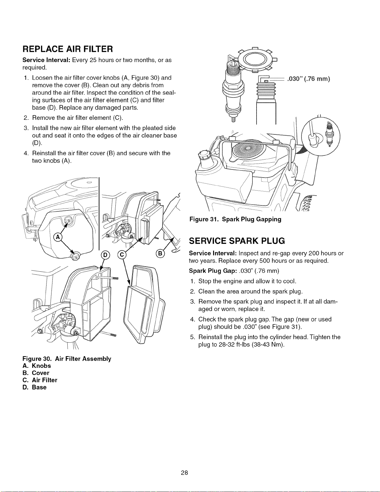
1. Loosen the air filter cover knobs (A, Figure 30) and
remove the cover (B). Clean out any debris from
around the air filter. Inspect the condition of the seal-
ing surfaces of the air filter element (C) and filter
base (D). Replace any damaged parts.
2. Remove the air filter element (C).
3. Install the new air filter element with the pleated side
out and seat it onto the edges of the air cleaner base
(D).
4. Reinstall the air filter cover (B) and secure with the
two knobs (A).
Figure 31. Spark Plug Gapping
Figure 30. Air Filter Assembly
A. Knobs
B. Cover
C. Air Filter
D. Base
SERVICE SPARK PLUG
Service Interval: Inspect and re-gap every 200 hours or
two years. Replace every 500 hours or as required.
Spark Plug Gap: .030" (.76 mm)
1. Stop the engine and allow itto cool.
2. Clean the area around the spark plug.
3. Remove the spark plug and inspect it. If at all dam-
aged or worn, replace it.
4. Check the spark plug gap. The gap (new or used
plug) should be .030" (see Figure 31).
5. Reinstall the plug into the cylinder head. Tighten the
plug to 28-32 ft-lbs (38-43 Nm).
28
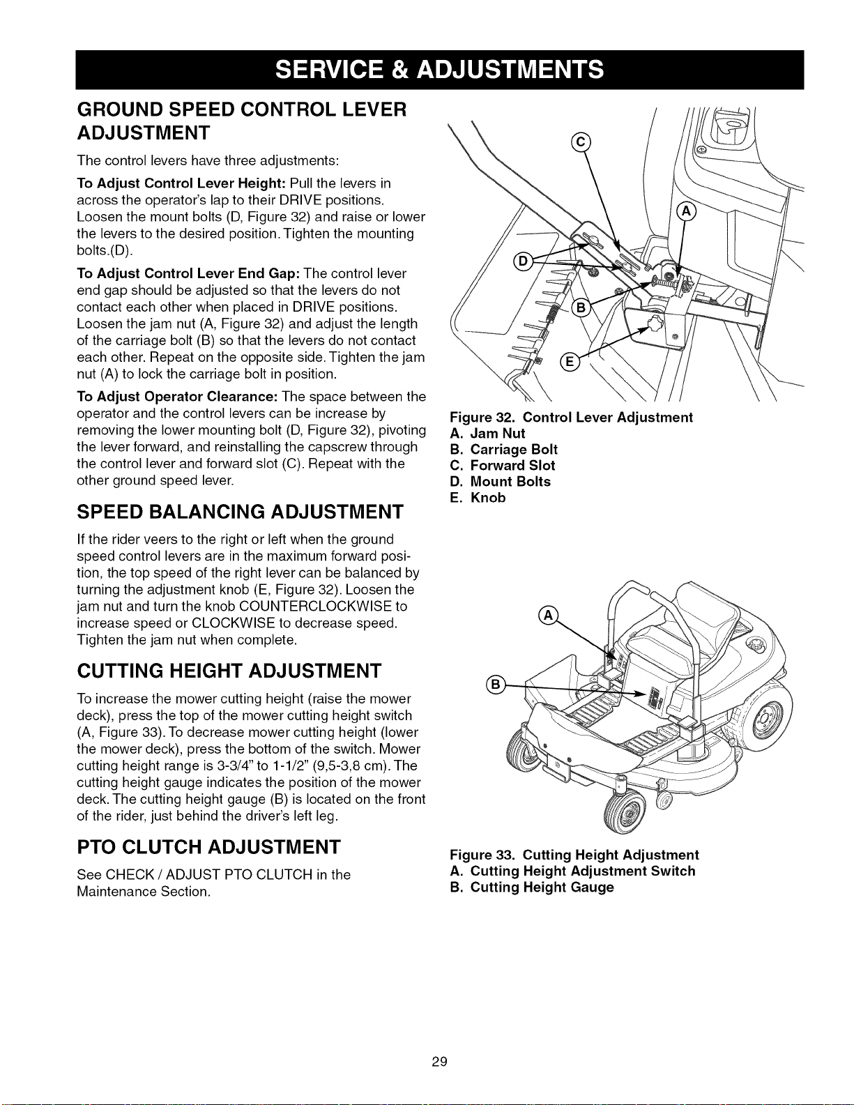
GROUND SPEED CONTROL LEVER
ADJUSTMENT
The control levers have three adjustments:
To Adjust Control Lever Height: Pull the levers in
across the operator's lap to their DRIVE positions.
Loosen the mount bolts (D, Figure 32) and raise or lower
the levers to the desired position. Tighten the mounting
bolts.(D).
To Adjust Control Lever End Gap: The control lever
end gap should be adjusted so that the levers do not
contact each other when placed in DRIVE positions.
Loosen the jam nut (A, Figure 32) and adjust the length
of the carriage bolt (B) so that the levers do not contact
each other. Repeat on the opposite side. Tighten the jam
nut (A) to lock the carriage bolt in position.
To Adjust Operator Clearance: The space between the
operator and the control levers can be increase by
removing the lower mounting bolt (D, Figure 32), pivoting
the lever forward, and reinstalling the capscrew through
the control lever and forward slot (C). Repeat with the
other ground speed lever.
SPEED BALANCING ADJUSTMENT
\
Figure 32. Control Lever Adjustment
A. Jam Nut
B. Carriage Bolt
C. Forward Slot
D. Mount Bolts
E. Knob
If the rider veers to the right or left when the ground
speed control levers are in the maximum forward posi-
tion, the top speed of the right lever can be balanced by
turning the adjustment knob (E, Figure 32). Loosen the
jam nut and turn the knob COUNTERCLOCKWISE to
increase speed or CLOCKWISE to decrease speed.
Tighten the jam nut when complete.
CUTTING HEIGHT ADJUSTMENT
To increase the mower cutting height (raise the mower
deck), press the top of the mower cutting height switch
(A, Figure 33). To decrease mower cutting height (lower
the mower deck), press the bottom of the switch. Mower
cutting height range is 3-3/4" to 1-1/2" (9,5-3,8 cm). The
cutting height gauge indicates the position of the mower
deck. The cutting height gauge (B) is located on the front
of the rider, just behind the driver's left leg.
PTO CLUTCH ADJUSTMENT
See CHECK / ADJUST PTO CLUTCH in the
Maintenance Section.
Figure 33. Cutting Height Adjustment
A. Cutting Height Adjustment Switch
B. Cutting Height Gauge
29
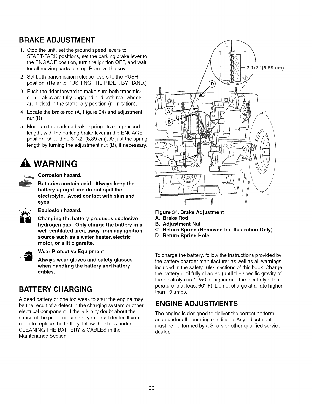
BRAKE ADJUSTMENT
1. Stop the unit, set the ground speed levers to
START/PARK positions, set the parking brake lever to
the ENGAGE position, turn the ignition OFF, and wait
for all moving parts to stop. Remove the key.
2. Set both transmission release levers to the PUSH
position. (Refer to PUSHING THE RIDER BY HAND.)
3. Push the rider forward to make sure both transmis-
sion brakes are fully engaged and both rear wheels
are locked in the stationary position (no rotation).
4. Locate the brake rod (A, Figure 34) and adjustment
nut (B).
5. Measure the parking brake spring. Its compressed
length, with the parking brake lever in the ENGAGE
position, should be 3-1/2" (8,89 cm). Adjust the spring
length by turning the adjustment nut (B), if necessary.
, WARNING
Corrosion hazard.
Batteries contain acid. Always keep the
battery upright and do not spill the
electrolyte. Avoid contact with skin and
eyes.
Explosion hazard.
Changing the battery produces explosive
hydrogen gas. Only charge the battery in a
well ventilated area, away from any ignition
source such as a water heater, electric
motor, or a lit cigarette.
Wear Protective Equipment
Always wear gloves and safety glasses
when handling the battery and battery
cables.
BATTERY CHARGING
A dead battery or one too weak to start the engine may
be the result of a defect in the charging system or other
electrical component. If there is any doubt about the
cause of the problem, contact your local dealer. Ifyou
need to replace the battery, follow the steps under
CLEANING THE BATTERY & CABLES in the
Maintenance Section.
3-1/2" (8,89 cm)
Figure 34. Brake Adjustment
A. Brake Rod
B. Adjustment Nut
C. Return Spring (Removed for Illustration Only)
D. Return Spring Hole
To charge the battery, follow the instructions provided by
the battery charger manufacturer as well as all warnings
included in the safety rules sections of this book. Charge
the battery until fully charged (until the specific gravity of
the electrolyte is 1.250 or higher and the electrolyte tem-
perature is at least 60° F). Do not charge at a rate higher
than 10 amps.
ENGINE ADJUSTMENTS
The engine is designed to deliver the correct perform-
ance under all operating conditions. Any adjustments
must be performed by a Sears or other qualified service
dealer.
30
 Loading...