

Page 1
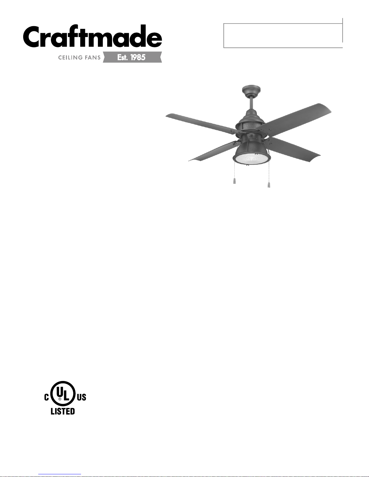
Installation Guide
READ THESE INSTRUCTIONS AND
SAVE THEM FOR FUTURE USE
For Model:
PAR52ESP4
Table of Contents:
Safety Tips. pg. 1
Unpacking Your Fan. pg. 2
Parts Inventory. pg. 2
Installation Preparation. pg. 3
Hanging Bracket Installation. pg. 3
Fan Assembly. pgs. 4 - 5
Wiring. pg. 6
Canopy Assembly. pg. 6
Blade Assembly. pg. 7
Switch Housing Assembly. pg. 7
Light Kit Assembly. pg. 8
Testing Your Fan. pg. 9
For
Wet Location
E192641
net weight of fan: 21.89 lb. (9.93 kg)
Troubleshooting. pg. 10
Warranty. pg. 10
Parts Replacement. pg. 10
PRINTED IN CHINA
Page 2

SAFETY TIPS.
WARNING: To reduce the risk of electrical shock, turn off the electricity to the fan at the main fuse box or circuit
panel before you begin the fan installation or before servicing the fan or installing accessories.
1. READ ALL INSTRUCTIONS AND SAFETY INFORMATION CAREFULLY BEFORE INSTALLING YOUR FAN
AND SAVE THESE INSTRUCTIONS.
CAUTION: To avoid personal injury, the use of gloves may be necessary while handling fan parts with sharp
edges.
2. Make sure all electrical connections comply with Local Codes or Ordinances, the National Electrical Code, and
ANSI/NFPA 70-1999. If you are unfamiliar with electrical wiring or if the house/building wires are different
colors than those referred to in the instructions, please use a qualified electrician.
3. Make sure you have a location selected for your fan that allows clear space for the blades to rotate, and at
least seven (7) feet (2.13 meters) of clearance between the floor and the fan blade tips. The fan should be
mounted so that the tips of the blades are at least thirty (30) inches (76 centimeters) from walls or other
upright structures.
4. The outlet box and ceiling support joist used must be securely mounted, and capable of supporting at least
35 pounds (16 kilograms). The outlet box must be supported directly by the building structure. Use only
CUL (Canada) or UL (USA) listed outlet boxes marked "FOR FAN SUPPORT."
WARNING: To reduce the risk of fire, electrical shock, or personal injury, mount to the outlet box marked
"Acceptable for Fan Support of 15.9 kg (35 lb) or less," and use the mounting screws provided with the outlet box.
Most outlet boxes commonly used for the support of lighting fixtures are not acceptable for fan support and may
need to be replaced. Consult a qualified electrician if in doubt.
WARNING: To reduce the risk of fire, electrical shock, or personal injury, wire connectors provided with this fan are
designed to accept only one 12 gauge house wire and two lead wires from the fan. If your house wire is larger than
12 gauge or there is more than one house wire to connect to the corresponding fan lead wires, consult an
electrician for the proper size wire connectors to use.
WARNING: If using this fan in a WET or damp location, this fan must be connected to a supply circuit that is
protected by a Ground Fault Circuit Interrupter (GFCI) to reduce the risk of personal injury, electrical shock or death.
5. Electrical diagrams are for reference only. Light kits that are not packed with the fan must be CUL (Canada) or
UL (USA) listed and marked suitable for use with the model fan you are installing. Switches must be CUL
(Canada) or UL (USA) general use switches. Refer to the instructions packaged with the light kits and
switches for proper assembly.
6. After installation is complete, check that all connections are absolutely secure.
7. After making electrical connections, spliced conductors should be turned upward and pushed carefully up
into the outlet box. The wires should be spread apart with the grounded conductor and the
equipment-grounding conductor on opposite sides of the outlet box.
WARNING: To reduce the risk of fire or electrical shock, do not use this fan with any solid state speed control device
or control fan speed with a full range dimmer switch. [Using a full range dimmer switch to control fan speed will
cause a loud humming noise from fan.] (Note: This fan is suitable for use with remote control approved for WET
locations.)
8. Do not operate the reverse switch until the fan has come to a complete stop.
9. Do not insert anything between the fan blades while they are rotating.
WARNING: To reduce the risk of personal injury, do not bend the blade arms during assembly or after installation.
Do not insert objects into the path of the blades.
WARNING: To avoid personal injury or damage to the fan and other items, be cautious when working around or
cleaning the fan.
10. Do not use water or detergents when cleaning the fan or fan blades. A soft cloth or lightly dampened cloth
will be suitable for most cleaning.
WARNING: To reduce the risk of personal injury, use only parts provided with this fan. The use of parts OTHER
than those provided with this fan will void the warranty.
NOTE: The important safety precautions and instructions appearing in the manual are not meant to cover all
possible conditions and situations that may occur. It must be understood that common sense and caution are
necessary factors in the installation and operation of this fan.
page 1
Page 3
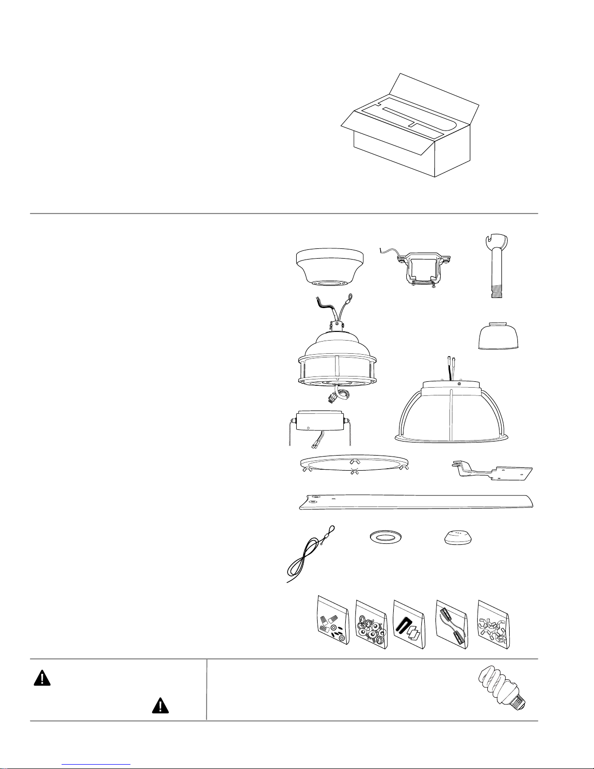
1. Unpacking Your Fan.
Carefully open the packaging. Remove items
from Styrofoam inserts. Remove motor housing
and place on carpet or Styrofoam to avoid
damage to finish. Do not discard fan carton or
Styrofoam inserts should this fan need to be
returned for repairs.
Check against parts inventory that all parts have
been included.
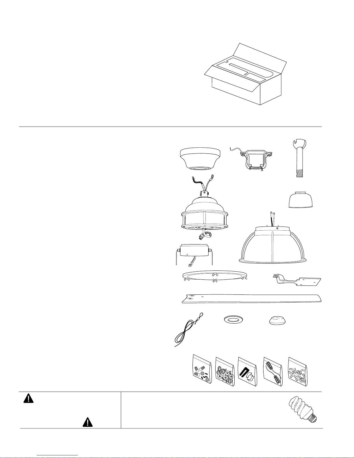
2. Parts Inventory.
b. hanging bracket.1 piece
c. downrod and hanging ball. 1 piece
d. motor housing. 1 piece
e. yoke cover. 1 piece
f. switch housing. 1 piece
g. light kit fitter. 1 piece
h. glass shade. 1 piece
i. blade arm. 4 pieces
a. canopy. 1 piece
j. blade. 4 pieces
a
d
f
h
j
b
g
c
e
i
k. safety cable (already attached to motor).
l. canopy cover (in hardware pack). 1 piece
m. weatherproof hanging ball cover. 1 piece
n. hardware packs
IMPORTANT REMINDER: You must
use the parts provided with this fan for
proper installation and safety.
1 piece
page 2
k
n
l
m
bulb required:
1 x 13 watt medium base compact
fluorescent bulb (included)
Page 4
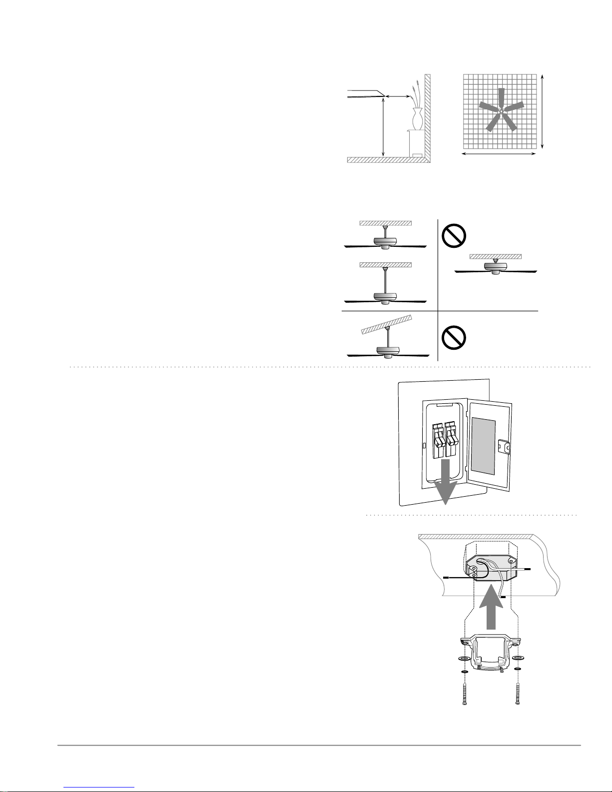
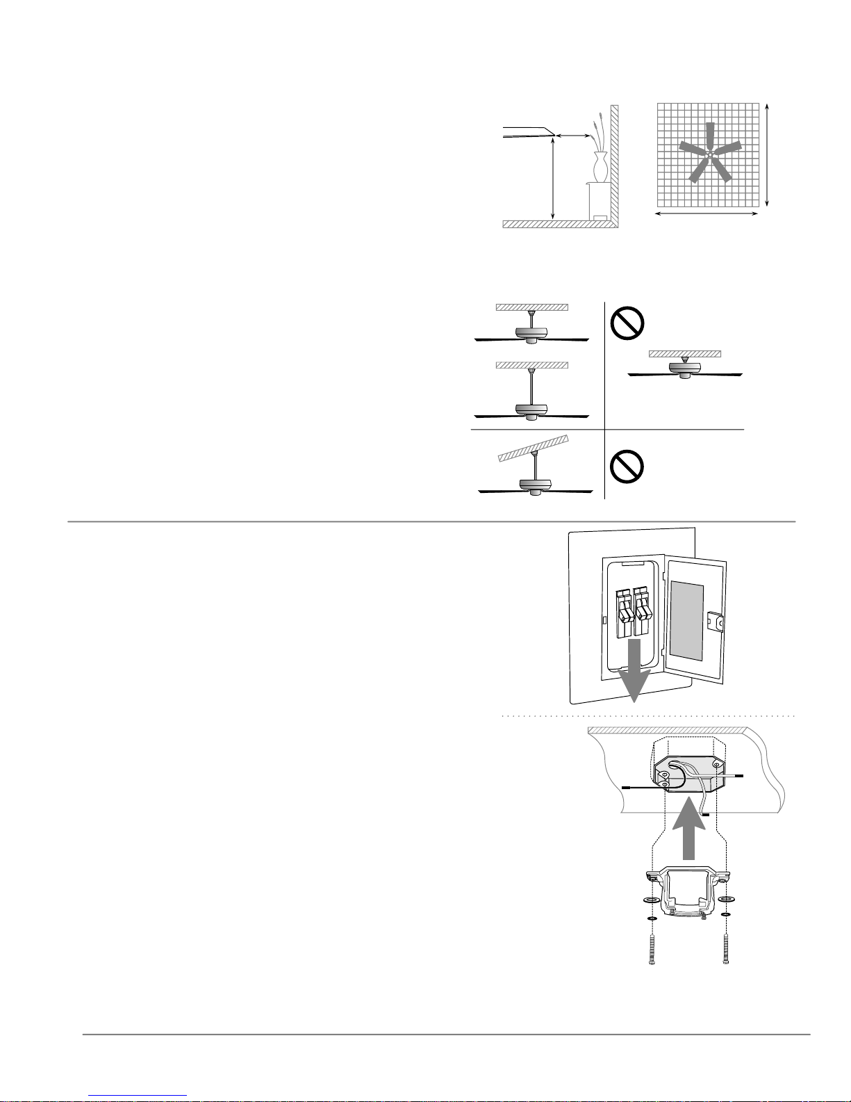
3. Installation Preparation.
blade edge
To prevent personal injury and damage, ensure
that the hanging location allows the blades a
clearance of 7ft. (2.13m) from the floor and 30in.
(76cm) from any wall or obstruction.
This fan is suitable for room sizes up to 400
square feet (37.2 square meters).
This fan can be mounted with a downrod
on a regular (no-slope) or vaulted ceiling. The
hanging length can be extended by purchasing
a longer downrod (0.5in. /1.27cm diameter).
Other installation, such as flushmount, is not
available for this fan.
Installation requires these tools:
Phillips screwdriver, flathead screwdriver,
adjustable pliers or wrench, stepladder, wire
cutters, and rated electrical tape.
inches
7 feet
(76cm)
(2.13m)
downrod
installation
30
12ft. - 20ft.
(3.66m - 6.1m)
12ft. - 20ft.
(3.66m - 6.1m)
flushmount
installation
Vaulted ceiling
angle is not to
exceed 25 degrees.
4. Hanging Bracket Installation.
Turn off circuit breakers to current fixture from breaker
panel and be sure operating light switch is turned to the
OFF position.
WARNING: Failure to disconnect power supply prior to
installation may result in serious injury.
Remove existing fixture.
WARNING: When using an existing outlet box, be sure the
outlet box is securely attached to the building structure and
can support the full weight of the fan. Ensure the outlet box is
clearly marked "Suitable for Fan Support." If not, it must be
replaced with an approved outlet box. Failure to do so can
result in serious injury.
CAUTION: Be sure outlet box is grounded properly and that
a ground wire (GREEN or bare) is present.
Install hanging bracket to outlet box using original
screws, spring washers and flat washers provided with
new or original outlet box.* If installing on a vaulted
ceiling, face opening of hanging bracket towards high
point of ceiling. Arrange electrical wiring around the back
of the hanging bracket and away from the bracket
opening.
ON
OFF
hanging bracket
flat washers
spring washers
outlet box screws
ON
OFF
*Note: It is very important that you use the proper hardware
when installing the hanging bracket as this will support the fan.
page 3
Page 5
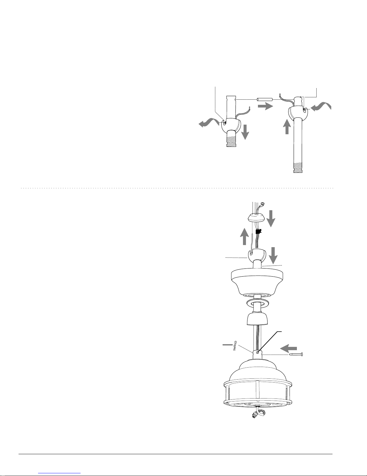
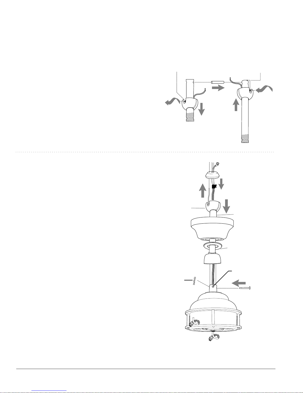
5. Fan Assembly.
If you wish to extend the hanging length of your fan,
you must remove the hanging ball from the
downrod provided to use with an extended downrod
(sold separately). [If you wish to use the downrod
provided, please proceed to instructions following the
dotted line below.]
set screw
set screw hole
stop pin
To remove hanging ball, loosen set screw on hanging
ball, lower hanging ball and remove stop pin. Slide
hanging ball off the original downrod, A, and slide it
down the longer downrod, B (the top of the downrod
should be noted as having a set screw hole; use this
hole when setting the set screw). Insert stop pin into
top of extended downrod and raise hanging ball. Be
sure stop pin aligns with slots on the inside of the
hanging ball. Tighten set screw securely.
Tip: To prepare for threading electrical wires through
downrod, apply a small piece of electrical tape to the
ends of the electrical wires--this will keep the wires
together when threading them through the downrod.
Locate canopy cover in hardware pack. Loosen yoke
set screws and nuts at top of motor housing. Remove
pin and clip from motor housing yoke. Slide downrod
through canopy, canopy cover and weatherproof yoke
cover. [Note: Canopy cover must be turned with shiny
side toward the motor housing.]
Thread safety cable and electrical wires through
downrod and pull extra wire slack from the upper end
of the downrod.
A
electrical wiring
hanging
ball
hanging ball
B
safety cable
weatherproof hanging
ball cover
downrod
canopy
Thread downrod into the motor yoke until holes for
pin and clip in downrod align with holes in
yoke--make sure wires do not get twisted. Re-insert pin
and clip. Tighten yoke set screws and nuts securely.
Lower weatherproof yoke cover to motor housing.
Remove electrical tape from electrical wiring and
thread each of the wires through a different hole in
the weatherproof hanging ball cover. Thread the
safety cable with the green (ground) wire. Pull
weatherproof hanging ball cover down securely over
hanging ball (on downrod).
["Fan Assembly" continued on next page.]
NOTE: The important safety precautions and
instructions appearing in the manual are not meant to
cover all possible conditions and situations that may
occur. It must be understood that common sense and
caution are necessary factors in the installation and
operation of this fan.
canopy cover
weatherproof
yoke cover
yoke set screw
clip
pin
motor
housing
page 4
Page 6
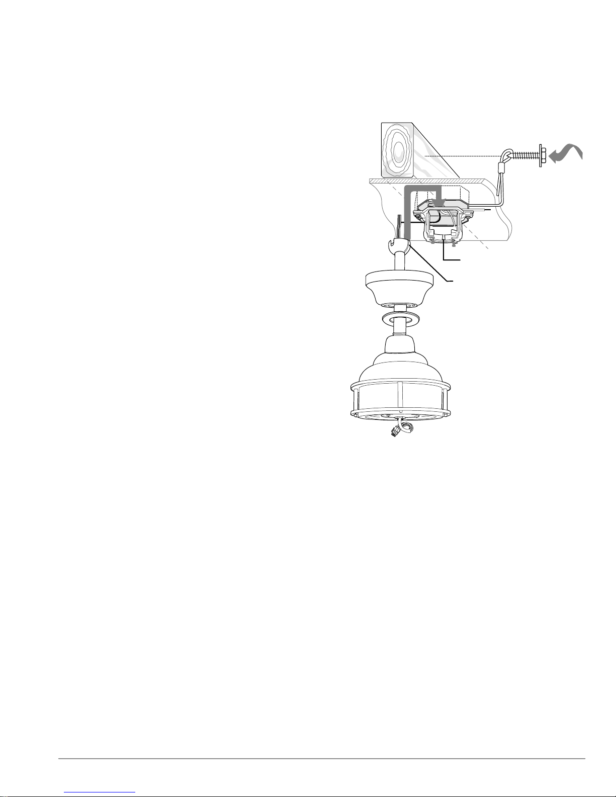
5. Fan Assembly (cont.)
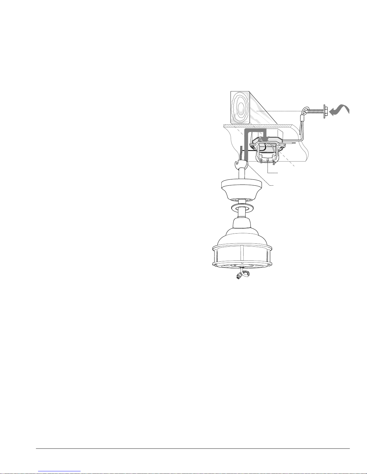
With the hanging bracket secured to the
outlet box and able to support the fan, you are
now ready to hang your fan. Grab the fan
firmly with two hands. Slide downrod through
opening in hanging bracket and let hanging
ball rest on the hanging bracket. Turn the
hanging ball slot until it lines up with the
hanging bracket tab.
WARNING: Failure to align slot in hanging ball
with tab in hanging bracket may result in
serious injury or death.
wood
ceiling
joist
safety cable loop
hanging bracket tab
Tip: Seek the help of another person to hold
the stepladder in place and to help lift the fan
up to you once you are set on the ladder.
Find a secure attachment point (wood ceiling
joist highly recommended) and secure safety
cable. It will be necessary to use a heavy duty
wood screw, washer and lock washer (not
supplied) with the safety cable loop. If
necessary, adjust the loop at the end of the
safety cable. The loop at the end of the safety
cable should just fit over the threads on the
wood screw. Extra cable slack can be left in
ceiling area.
hanging ball slot
motor housing
page 5
Page 7
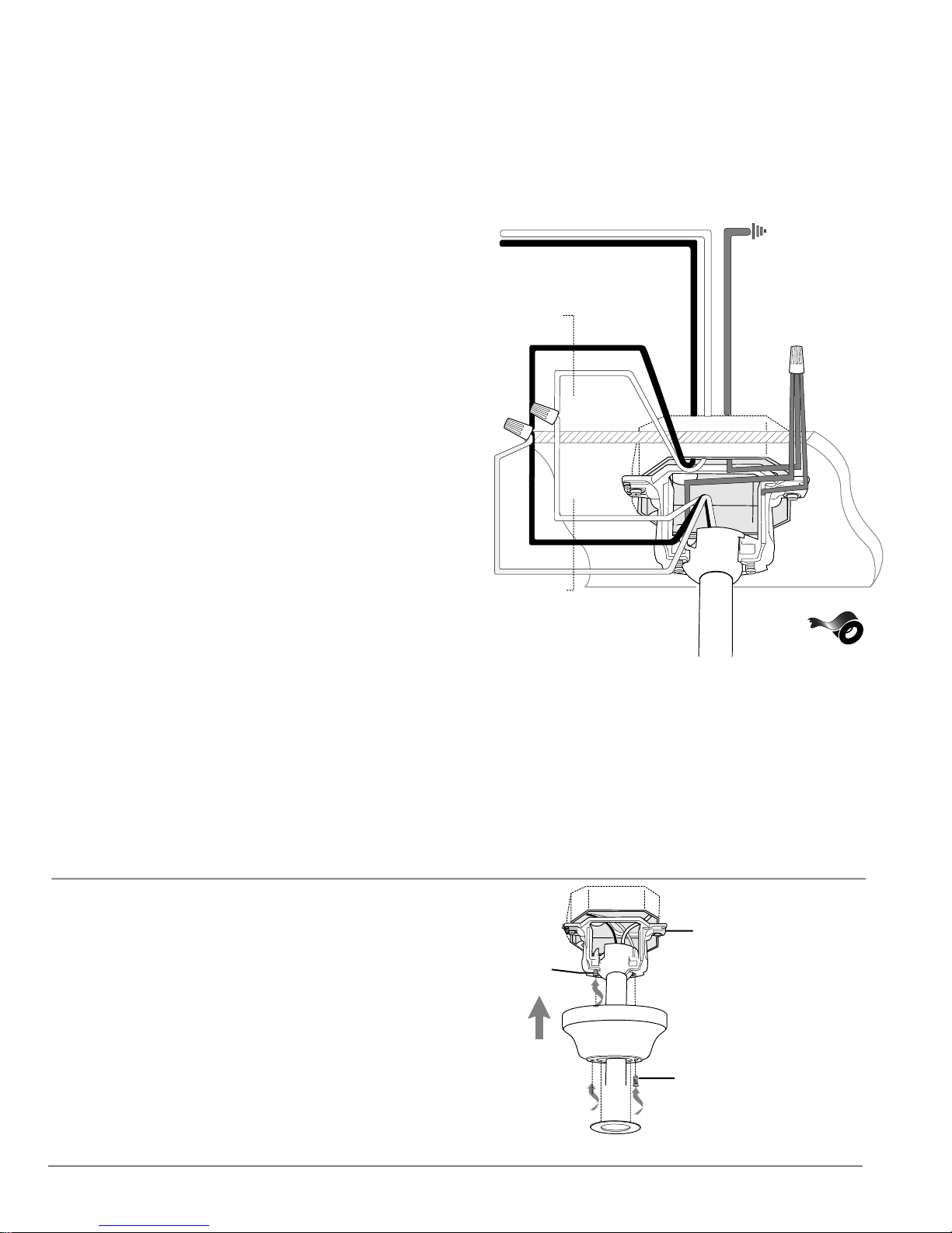
6. Wiring.
CAUTION: Be sure outlet box is properly grounded
and that a ground wire (GREEN or Bare) is present.
Make sure all electrical connections comply with
Local Codes or Ordinances and the National Electrical
Code. If you are unfamiliar with electrical wiring or if
the house/building wires are different colors than
those referred to in the instructions below, please use
a qualified electrician.
Note: Excess lead wire length from the fan can be cut
to the desired length and then stripped.
WARNING: If using this fan in a WET or DAMP
location, this fan must be connected to a supply
circuit that is protected by a Ground Fault Circuit
Interrupter (GFCI) to reduce the risk of personal
injury, electrical shock or death.
When fan is secured in place on the hanging
bracket, electrical wiring can be made as follows:
Connect BLACK and BLUE wires from fan to
BLACK wire from ceiling with wire connector
provided.
Connect WHITE wire from fan to WHITE wire from
ceiling with wire connector provided.
Connect all GROUND (GREEN) wires together
from fan to BARE/GREEN wire from ceiling with
wire connector provided.
If you intend to control the fan light with a
separate light switch connect BLUE wire from fan
to the BLACK (or RED) supply from the
independent switch.
white supply wire
black supply wire
from ceiling
black
white
white
black
blue
from fan
ground
(green or bare)
*
This fan is remote control adaptable (remote
control sold separately). Note: Only remote
controls approved for WET locations can be used
with this fan.
ground
(green
or bare)
* Wrap each wire connector separately with
electrical tape as an extra safety measure.
7. Canopy Assembly.
Locate 2 screws on underside of hanging bracket
and remove screw closest to the open end of the
hanging bracket. Partially loosen the other screw.
Lift canopy to hanging bracket. Place rounded
part of slotted hole in canopy over loosened screw
in hanging bracket and push up. Twist canopy to
lock. Re-insert screw that was removed, and then
tighten both screws securely. Slide canopy cover
up to canopy, aligning rounded part of slotted
holes in canopy cover with screw heads in bottom
of canopy. Turn canopy cover to right (clockwise)
until it stops.
hanging bracket
screw
canopy
screw
canopy cover
page 6
Page 8
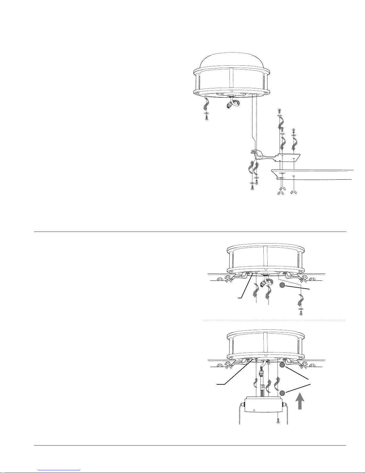
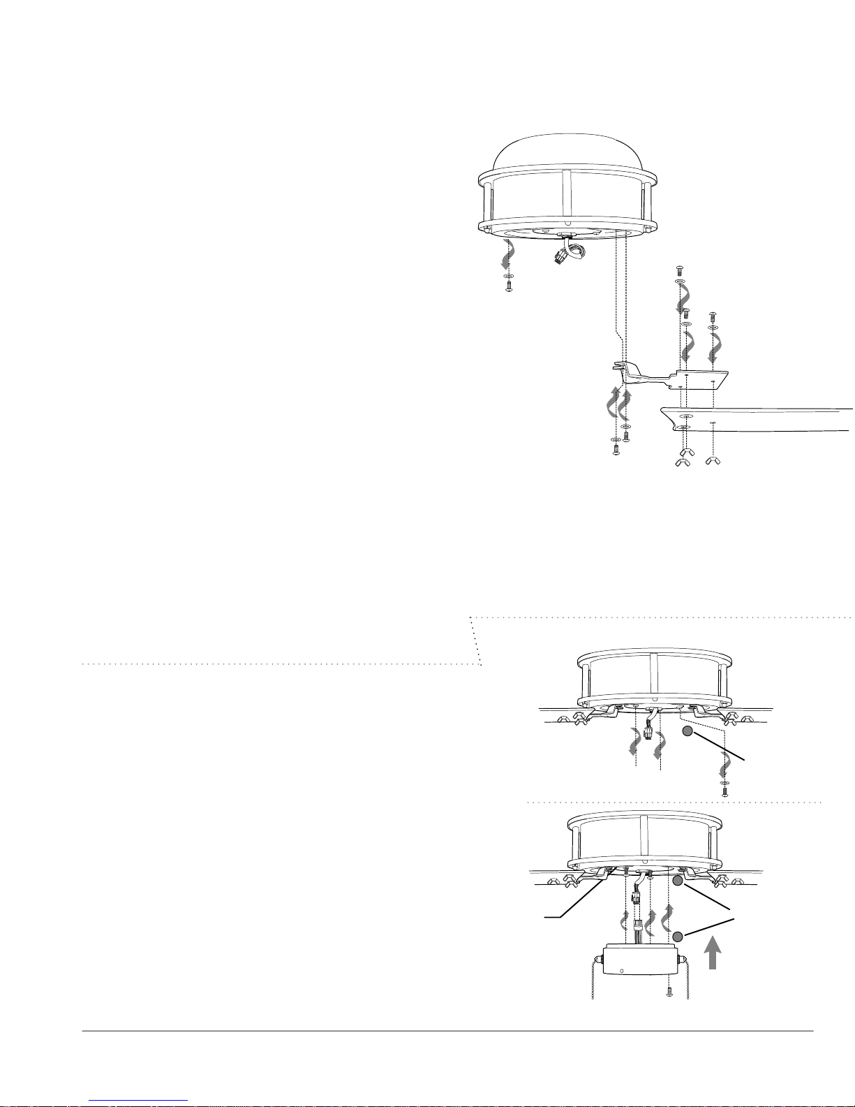
8. Blade Assembly.
Time Saver: Washers for blade screws can be set on
each blade screw prior to installing blades.
Locate 12 blade attachment screws and washers and
12 wing nuts in one of the hardware packs. Place blade
arm on TOPSIDE of blade, aligning holes in blade arm
with holes in blade as shown. [Be sure to note label on
blade indicating THIS SIDE UP and turn blade so that
label faces up.] With fingers, insert 3 blade attachment
screws (along with washers) from the TOPSIDE of blade
and 3 wing nuts from UNDERSIDE of blade, making
sure to completely insert each screw so that the blade
arm can be attached correctly. Repeat procedure for
remaining blades.
Remove blade arm screws and lock washers from
underside of motor. [WARNING: Do NOT remove the 4
screws located on the inner rim of the underside of the
motor housing--doing so or any attempt at doing so
will void the warranty.] Align blade arm holes with
motor screw holes and attach blade arm with lock
washers and blade arm screws. Before securing screws
permanently, repeat this procedure with remaining
blade arms. Secure all screws.
Note: Tighten blade arm screws twice a year.
lock washers
blade arm
screws
motor housing
blade attachment
screws and washers
blade arm
blade
wing nuts
9. Switch Housing Assembly.
Remove 1 screw (next to red dot) from motor
plate on underside of motor and partially loosen
the other 2 screws.
Align red dot inside switch housing with red dot
on motor plate. Align slotted holes in center of
switch housing with loosened screws in motor
plate, allowing male plug from motor housing to
come through hole in middle of switch housing.
Twist switch housing to lock. Re-insert screw that
was previously removed and securely tighten all
screws with Phillips screwdriver.
Connect male plug from motor housing to female
plug from switch housing. Be sure that the plugs
connect completely.
motor housing
motor plate
motor housing
motor
plate
male
plug
female
plug
red dot
red dot
switch housing
page 7
Page 9
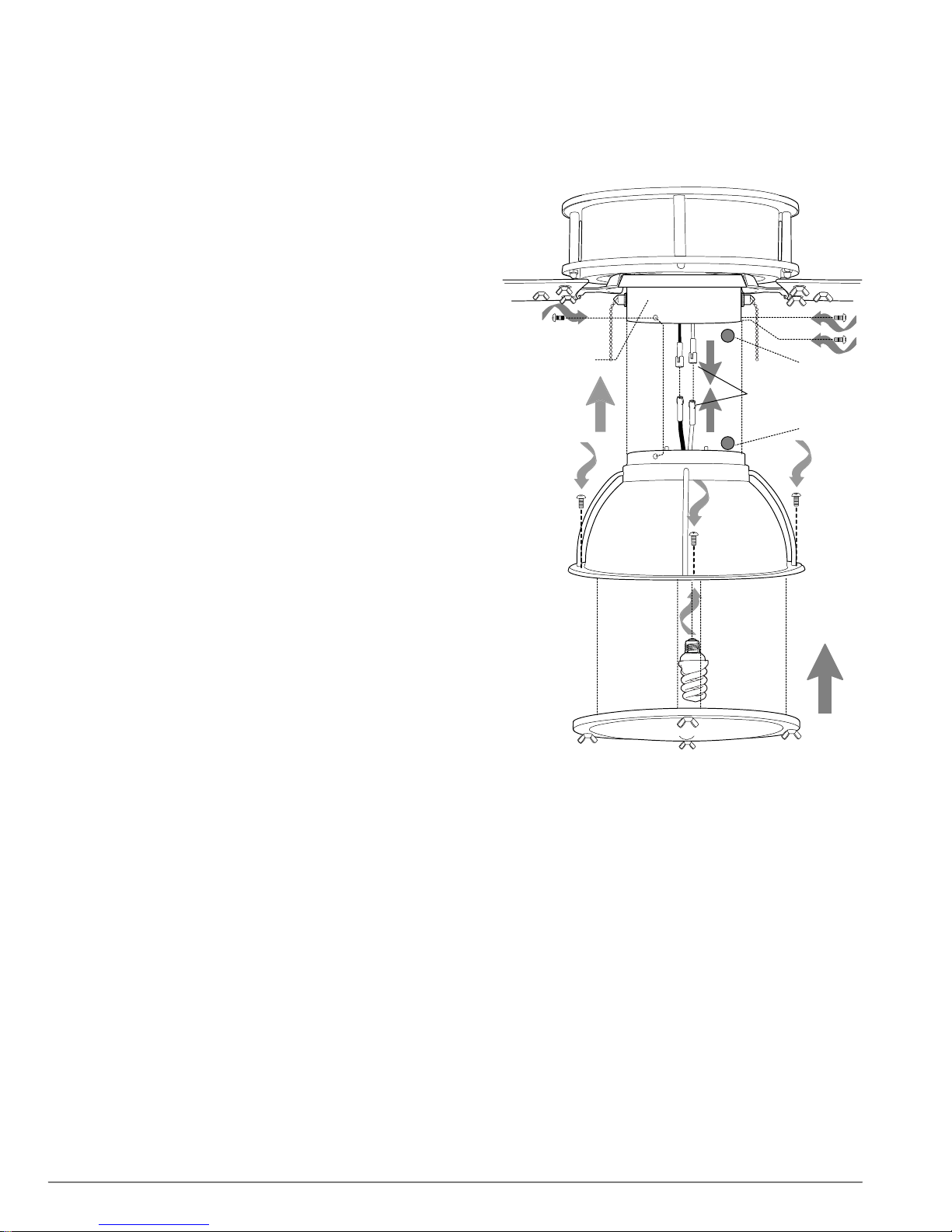
10. Light Kit Assembly.
Remove 3 screws from light kit fitter.
Connect the WHITE wire from the light kit fitter to
the WHITE wire from motor housing. Connect the
BLACK wire from the light kit fitter to the BLUE (or
BLACK) wire from the motor housing. Be sure the
molex connections snap together securely.
Align red dot on light kit fitter with red dot inside
switch housing. Align holes in light kit fitter with
holes in switch housing. Attach light kit fitter with 3
screws that were previously removed. Secure all 3
screws with Phillips screwdriver.
Install 1 medium base 13 watt max. compact
fluorescent bulb (included).
Important: When replacing bulb, please allow bulb
and shade to cool down before touching them.
Remove 4 larger screws from the tabs in the shade.
Align holes in light kit fitter with holes in the shade.
Attach shade with 4 screws that were just removed.
motor housing
switch housing
light kit
fitter
red dot
molex
connections
red dot
larger
screws
Important: DO NOT remove the wing nuts in shade.
bulb
shade
page 8
Page 10
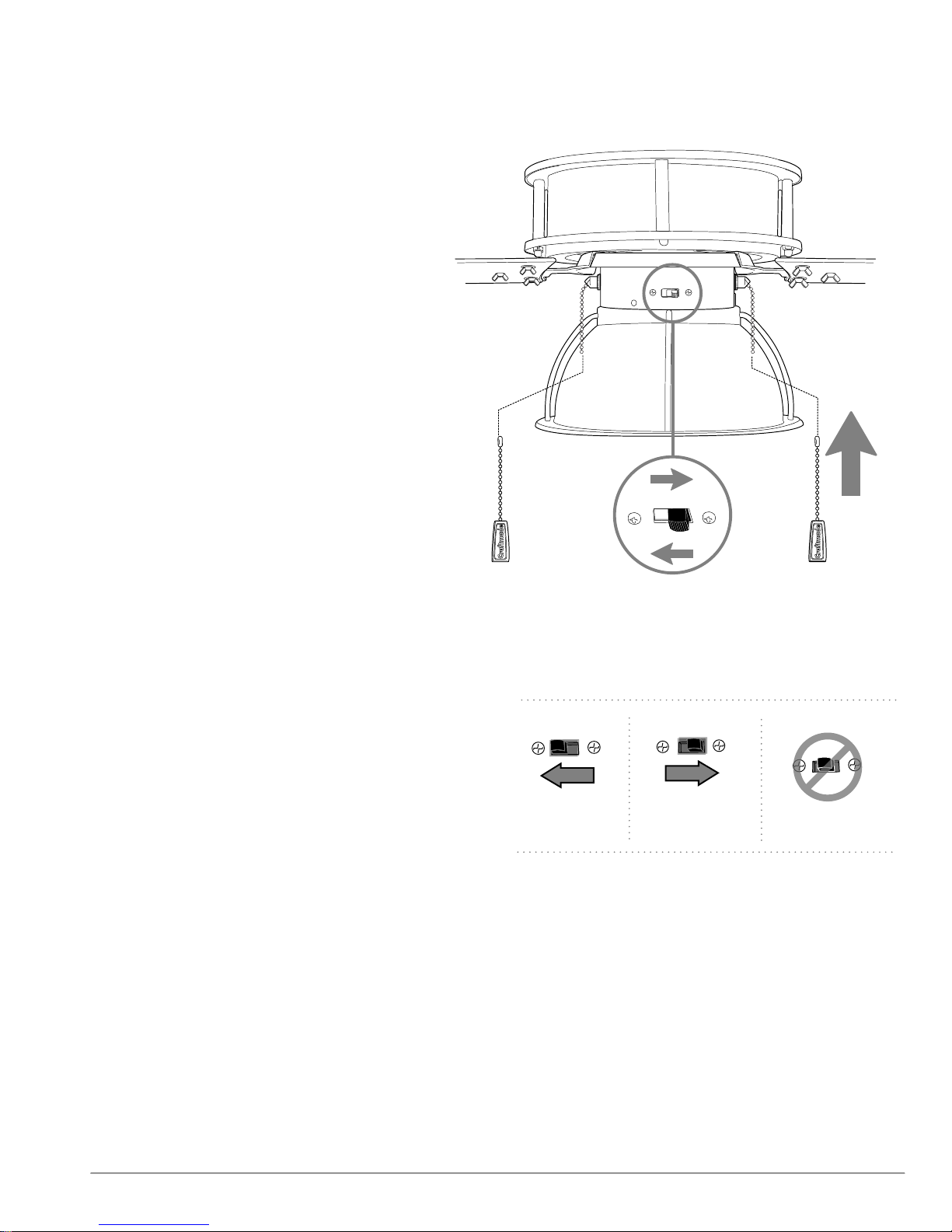
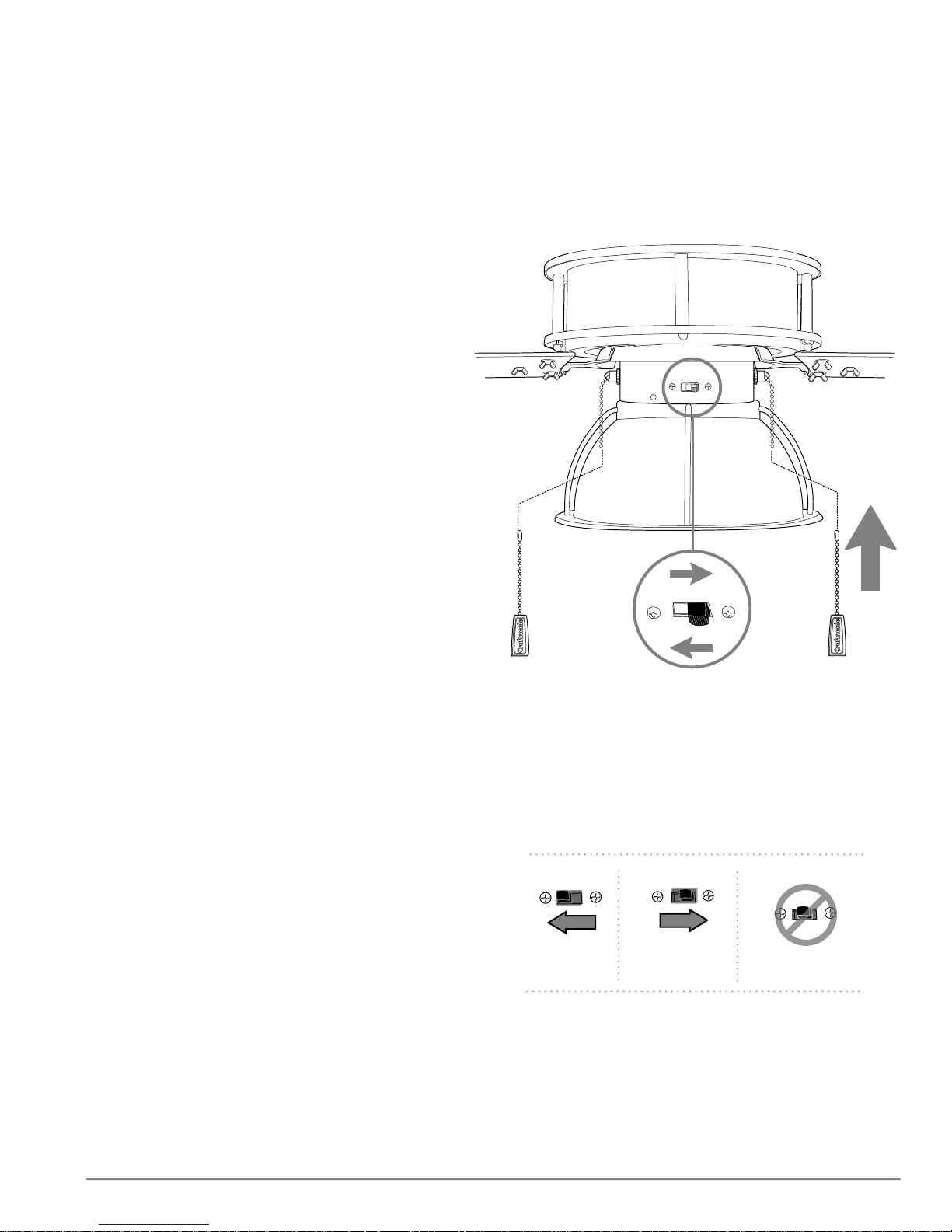
11. Testing Your Fan.
It is recommended that you test fan before
finalizing installation. Restore power from
circuit box and light switch (if applicable).
Test fan speeds with the pull chain labeled
FAN. Start at the OFF position (no blade
movement). First pull will set the fan to HI.
Second pull will set the fan to MEDIUM.
Third pull will set the fan to LOW. Fourth pull
will again set the fan to the OFF setting. Test
light with the pull chain labeled LIGHT.
(diagram 1) If fan and/or light do (does) not
function, please refer to "Troubleshooting"
section to solve any issues before
contacting Customer Service.
Turn fan completely off before moving the
reverse switch. Set reverse switch to
recirculate air depending on the season:
- LEFT position in summer (diagram 2)
- RIGHT position in winter (diagram 3)
A ceiling fan will allow you to raise your
thermostat setting in summer and lower
your thermostat setting in winter without
feeling a difference in your comfort.
Important: Reverse switch must be set
either completely LEFT or completely RIGHT
for fan to function. If the reverse switch is set
in the middle position (diagram 4), fan will
not operate.
motor housing
light
pull chain
extension
diagram 1
diagram 1
reverse switch
fan
pull chain
extension
Note: Do NOT remove weatherproof cover
from reverse switch.
Attach pull chain extensions supplied or
custom pull chain extensions (sold
separately) to ends of the pull chains.
page 9
diagram 2
diagram 3
diagram 4
Page 11

Troubleshooting.
Problem: Fan fails to operate.
Solutions:
1. Check wall switch to fan.
2. Verify that reverse switch is set completely in
either direction.
3. Check to be sure fan is wired properly.
Problem: Light kit not lighting.
Solutions:
1. Check wall switch to fan.
2. Check that bulb is installed correctly.
3. Check to be sure wires in canopy are wired
properly.
4. Verify that male and female plugs in switch
housing are connected properly.
Problem: Fan operates but light fails.
Solutions:
1. Check that bulb is installed correctly.
2. Check to be sure wires in canopy are wired
properly.
3. Verify that male and female plugs in switch
housing are connected properly.
4. Replace defective bulb with same type of bulb.
Problem: Fan wobbles.
Solutions:
1. Use the balancing kit provided in one of the
hardware packs. If no blade balancing kit is
provided, please call Customer Support,
1-800-486-4892, to request one.
2. Check to be sure set screw(s) on motor housing
yoke is (are) tightened securely.
3. Check to be sure set screw on hanging ball is
tightened securely.
Warranty.
CRAFTMADE/ELLINGTON LIFETIME WARRANTY:
CRAFTMADE/ELLINGTON warrants this fan to the original
household purchaser for indoor use under the following
provisions:
1-YEAR WARRANTY: CRAFTMADE/ELLINGTON will replace
or repair any fan which has faulty performance due to a
defect in material or workmanship. Contact
Craftmade/Ellington Customer Service at 1-800-486-4892
to arrange for return of fan. Return fan, shipping prepaid, to
Craftmade/Ellington. We will repair or ship you a
replacement fan, and we will pay the return shipping cost.
5-YEAR WARRANTY: CRAFTMADE/ELLINGTON will repair or
replace at no charge to the original purchaser any fan
motor that fails to operate satisfactorily when failure
results from normal use.
RETURN FAN MOTOR ONLY, shipping prepaid, to
Craftmade/Ellington. We will repair or ship purchaser a
replacement motor and Craftmade/Ellington will pay the
return shipping cost.
6-YEAR to LIFETIME LIMITED WARRANTY:
CRAFTMADE/ELLINGTON will repair the fan, at no charge
for labor only to the original purchaser, if the fan motor
fails to operate satisfactorily when failure results from
normal use. Parts used in the repair will be billed to the
purchaser at prevailing prices at time of repair.
The purchaser shall be responsible for all costs incurred
in the removal, reinstallation and shipping of the product
for repairs.
This warranty does not apply when damage from
mechanical, physical, electrical or water abuse results in
causing the malfunction. Deterioration of finishes or other
parts due to time or exposure to salt air is specifically
exempted under this warranty.
Neither Craftmade/Ellington nor the manufacturer will
assume any liability resulting from improper installation or
use of this product. In no case shall the company be liable
for any consequential damages for breach of this, or any
other warranty expressed or implied whatsoever. This
limitation as to consequential damages shall not apply in
states where prohibited.
Parts Replacement.
For parts and information, please refer to
"Parts Inventory" on page 2.
Craftmade/Ellington Customer Support:
1-800-486-4892
www.craftmadebrands.com
page 10
Page 12
Guía de instalación
Para modelo:
LEER ESTAS INSTRUCCIONES Y
GUARDARLAS PARA UTILIZACION FUTURA
PAR52ESP4
Indice de materias:
Sugerencias de seguridad. Pág. 1
Desempaquetado del ventilador. Pág. 2
Inventario de piezas. Pág. 2
Preparación para la instalación. Pág. 3
Instalación del soporte de montaje. Pág. 3
Ensamblaje del ventilador. Págs. 4 - 5
Instalación eléctrica. Pág. 6
Colocación de la cubierta decorativa. Pág. 6
Colocación de las aspas. Pág. 7
Instalación de la caja de encendido. Pág. 7
Instalación del juego de luz. Pág. 8
Verificación del funcionamiento del
ventilador. Pág. 9
Localización de fallas. Pág. 10
For
Wet Location
E192641
peso neto del ventilador: 9,93 kg (21,89 lb)
REGISTRADO PARA
LUGAR MOJADO
Piezas de repuesto. Pág. 10
Garantía. Pág. 10
IMPRESO EN CHINA
Page 13

SUGERENCIAS DE SEGURIDAD.
ADVERTENCIA: Para evitar la posibilidad de una descarga eléctrica, desconectar la corriente en la caja de fusibles
principal o el interruptor protector antes de iniciar la instalación del ventilador o antes de repararlo o instalar accesorios.
1. LEER TODAS LAS INSTRUCCIONES E INFORMACIÓN DE SEGURIDAD CUIDADOSAMENTE ANTES DE INSTALAR
SU VENTILADOR Y GUARDAR ESTAS INSTRUCCIONES.
PRECAUCION: Para reducir el riesgo de daño corporal, es posible que sea necesario usar guantes al manejar las piezas
del ventilador que tengan bordes afilados.
2. Asegurarse de que todas las conexiones eléctricas cumplan con los Códigos o las Ordenanzas Locales, el Código
Nacional Eléctrico y ANSI/NFPA 70-1999. Si usted no está familiarizado con el alambrado eléctrico o los cables
de la casa/el edificio son de colores diferentes a los cuales se refieren en las instrucciones, favor de buscar un
electricista calificado.
3. Asegurarse de que haya localizado una ubicación para su ventilador que permite el espacio necesario para la
rotación de las aspas, y por lo menos 2,13 metros (7 pies) de espacio libre entre el piso y las puntas de las aspas.
Debe instalar el ventilador para que las puntas de las aspas queden a una distancia de por lo menos 76
centímetros (30 pulgadas) de las paredes y otras estructuras verticales.
4. La caja de salida eléctrica debe estar bien sujetado a la viga de soporte del techo y deben ser capaces de sostener
por lo menos 16 kilogramos (35 libras). La caja debe tener apoyo directo de la estructura del edificio. Sólo usar
cajas de salida registradas con
SUPPORT" en inglés).
ADVERTENCIA: Para reducir el riesgo de incendio, descarga eléctrica o daño corporal, instalar en la caja de salida
marcada "Aceptable para sostener ventilador de 15,9 kg (35 lb) o menos" ["Acceptable for Fan Support of 15.9 kg (35 lb)
or less"] y utilizar los tornillos proporcionados con la caja de salida. La mayoría de las cajas de salida que normalmente se
usan para sostener los aparatos de alumbrado no siempre son apropiadas para sostener ventiladores y es posible que las
tenga que reemplazar. En caso de duda, consultar con un electricista calificado.
ADVERTENCIA: Para reducir el riesgo de incendio, descarga eléctrica o daño corporal, los conectores para cable
provistos con este ventilador son diseñados para aceptar sólo un cable de calibre 12 de la casa y dos cables principales
del ventilador. Si el calibre del cable de la casa es superior al 12 o hay más de un cable de la casa para conectar a los
cables principales del ventilador al cual corresponda cada uno, consultar con un electricista para informarse sobre el
tamaño correcto de conectores para cable que se debe usar.
CUL (Canadá) o UL (EEUU) que indican que "sirven para ventilador" ("FOR FAN
ADVERTENCIA: Si va a utilizar este ventilador en un lugar MOJADO o HUMEDO, hay que conectar el ventilador a un
circuito de alimentación que esté protegido por un Interruptor de Circuito de Falla de Tierra (GFCI, por sus siglas en
inglés) para reducir el riesgo de daño corporal, descarga eléctrica o la muerte.
5. Los diagramas eléctricos son únicamente para referencia. Los juegos de luz que no se incluyen con el ventilador
deben tener el símbolo
ventilador. Los interruptores deben ser interruptores de uso general
instrucciones incluidas con el juego de luz y los interruptores para ensamblarlos correctamente.
6. Después de haber terminado la instalación, asegurarse de que todas las conexiones estén totalmente seguras.
7. Después de haber terminado todas las conexiones eléctricas, los conductores empalmados deben ser volteados
para arriba y colocados cuidadosamente dentro de la caja de salida. Los alambres se deben de separar con el
conductor a tierra a un lado y el conductor a tierra del equipo al lado opuesto.
ADVERTENCIA: Para reducir el riesgo de incendio o descarga eléctrica, no usar el ventilador con ningún control de
velocidad de estado sólido ni controlar la velocidad del ventilador con un interruptor con reductor de luz de gama
completa. [El usar un interruptor con reductor de luz de gama completa para controlar la velocidad del ventilador
causará un zumbido recio del ventilador.] (Nota: Este ventilador sí sirve para usar con control remoto que tenga
aprobación para lugares MOJADOS.)
8. No utilizar el interruptor de reversa hasta que el ventilador se haya parado completamente.
9. No insertar ningún objeto entre las aspas mientras estén rotando.
ADVERTENCIA: Para reducir el riesgo de daño corporal, no doblar los brazos de las aspas durante el ensamblaje ni
durante la instalación. No insertar objetos entre las aspas mientras estén rotando.
ADVERTENCIA: Para reducir el riesgo de daño corporal o algún daño al ventilador, tener cuidado al estar trabajando
alrededor del ventilador o limpiándolo.
10. No utilizar agua ni detergentes para limpiar el ventilador ni las aspas. Usar un trapo seco o ligeramente
húmedo para su limpieza general.
CUL (Canadá) o UL (EEUU) y también deben indicar que sirven para uso con este
CUL (Canadá) o UL (EEUU). Referirse a las
ADVERTENCIA: Para reducir el riesgo de daño corporal, usar sólo las piezas provistas con este ventilador. Al usar piezas
DISTINTAS a las provistas con este ventilador se invalidará la garantía.
NOTA: No se debe concluir que las precauciones de seguridad importantes e instrucciones en este manual van a abarcar
todas las condiciones y situaciones posibles que puedan ocurrir. Se debe entender que el sentido común y la precaución
son factores necesarios en la instalación y la operación de este ventilador.
página 1
Page 14
1. Desempaquetado del ventilador.
Abrir el empaque cuidadosamente. Sacar los artículos
del embalaje. Sacar el motor y ponerlo en una
alfombra o en el embalaje para evitar rayar el acabado.
Guardar la caja de cartón o el empaquetamiento
original en caso de que tenga que mandar el
ventilador para alguna reparación.
Comprobar las piezas del ventilador con el inventario
de piezas y verificar que se incluyeron todas.
2. Inventario de piezas.
a. cubierta decorativa. 1 unidad
b. soporte de montaje. 1 unidad
c. tubo y bola que sirve para colgar.
1 unidad
d. bastidor del motor. 1 unidad
e. cubierta del cuello. 1 unidad
f. caja de encendido. 1 unidad
g. conectador para el juego de luz. 1 unidad
h. pantalla de vidrio. 1 unidad
i. brazo para el aspa. 4 unidades
j. aspa. 4 unidades
k. cable de seguridad (fijado de antemano al
motor).1 unidad
l. tapa de la cubierta decorativa (en paquete de
artículos de ferretería). 1 unidad
a
d
f
h
j
k
b
g
l
m
c
e
i
m. cubierta a prueba de la intemperie para la
bola que sirve para colgar. 1 unidad
n.paquetes de artículos de ferretería
RECORDATORIO IMPORTANTE:
Se tienen que utilizar las piezas provistas
con este ventilador para una instalación
adecuada y su seguridad.
n
bombilla necesaria:
1 bombilla fluorescente compacta de base
mediana de 13 vatios (incluida)
página 2
Page 15
3. Preparación para la instalación.
Para prevenir daño corporal y otros daños, estar
seguro de que el lugar en donde va a colgar el
ventilador le permite un espacio libre de 2,13m (7 pies)
entre las puntas de las aspas y el piso y 76cm (30 pulg.)
entre las aspas y cualquier pared u otra obstrucción.
Este ventilador es adecuado para habitaciones hasta
37,2 metros cuadrados (400 pies cuadrados).
borde del aspa
76cm
2,13m
(7 pies)
pulg.)
(30
3,66m - 6,1m
12 pies - 20 pies
3,66m - 6,1m
Se puede colgar este ventilador con tubo en un
techo regular (sin inclinación) o abovedado. La
instalación
con tubo
longitud colgante se puede extender comprando un
tubo más largo (con diámetro de 1,27cm/0,5 pulg.).
No hay ningún otro tipo de instalación, como al ras
con el techo, disponible para este ventilador.
Se necesitan las herramientas siguientes para la
instalación:
Destornillador de estrella Phillips, destornillador de
paleta (plano), alicates ajustables o llave de tuercas,
escalera de tijera, cortaalambres y cinta aisladora.
4. Instalación del soporte de montaje.
Apagar los cortacircuitos en el panel de electricidad que suplen
corriente a la caja de salida y asegurarse de que el interruptor de
luz esté APAGADO.
ADVERTENCIA: El no desconectar el suministro de fuerza antes de
la instalación puede tener por resultado lesiones graves.
Quitar el aparato existente.
ADVERTENCIA: Si utiliza una caja de salida eléctrica existente,
asegurarse de que la caja de salida esté firmemente conectada a la
estructura del edificio y que sea capaz de sostener el peso total del
ventilador. Asegurarse de que la caja de salida indique claramente
que "Sirve para ventilador" (FOR FAN SUPPORT); si no, se debe
reemplazar con una caja de salida aprobada. El no hacer el cambio
si es necesario puede resultar en lesiones graves.
instalación al ras
con el techo
El ángulo de
inclina-ción de un techo
abovedado no puede
exceder 25 grados.
ON
ON
OFF
OFF
PRECAUCION: Asegurarse de que la caja de salida esté conectada
a tierra correctamente y que haya un conductor a tierra (cable
VERDE o pelado).
Instalar el soporte de montaje utilizando los tornillos originales,
las arandelas de resorte y las arandelas planas de su nueva o
existente caja de salida.* Si hace la instalación en un techo
abovedado, colocar el soporte de montaje con la abertura
dirigida hacia la parte alta del techo. Arreglar el alambrado
eléctrico (los cables) en la parte de atrás del soporte y lejos de la
abertura del soporte.
*Nota: Es muy importante usar los artículos de ferretería correctos
al instalar el soporte de montaje puesto que sirve para sostener el
ventilador.
soporte de montaje
arandelas planas
arandelas de resorte
tornillos de la
caja de salida
página 3
Page 16
5. Ensamblaje del ventilador.
Si usted desea extender la longitud colgante del
ventilador, usted tendrá que quitar la bola que sirve para
colgar del tubo provisto para usarla con un tubo más
largo (a la venta por separado). [Si desea utilizar el tubo
provisto, favor de pasar a las instrucciones después de la
línea punteada más abajo.]
Aflojar el tornillo de fijación de la bola que sirve para
colgar, bajar la bola que sirve para colgar y sacar el perno
de tope. Quitar la bola del tubo original, A, y deslizarla
sobre el tubo más largo, B (la parte de arriba del tubo
debe tener el agujero para el tornillo de fijación en ese
extremo; usar ese agujero al colocar el tornillo de fijación).
Introducir el perno de tope en la parte de arriba del tubo
más largo y subir la bola. Asegurarse de que el perno de
tope se ponga en línea con las ranuras dentro de la bola.
Apretar bien el tornillo de fijación.
Sugerencia: Para preparar los cables para pasarlos por el tubo,
poner un pedacito de cinta aisladora en la punta de los
cables--esto mantendrá los cables juntos al pasarlos por el
tubo.
Localizar la tapa de la cubierta decorativa en uno de los
paquetes de artículos de ferretería. Aflojar los tornillos de
fijación del cuello y las tuercas en la parte superior del bastidor
del motor y quitar el perno y la clavija del cuello del motor.
Pasar el tubo por la cubierta decorativa, la tapa de la cubierta
decorativa y la cubierta del cuello. [Nota: Se tiene que voltear
la tapa de la cubierta decorativa para que el lado brillante dé al
bastidor del motor.]
Pasar el cable de seguridad y los cables del ventilador a través
del tubo y con cuidado jalar el cableado en exceso por la parte
de arriba del tubo.
Enroscar el tubo en el cuello del motor hasta alinearse los
agujeros para el perno y la clavija en el tubo con los del
cuello—asegurarse de que no se tuerzan los cables. Volver a
introducir el perno y la clavija. Apretar bien los tornillos de
fijación del cuello y las tuercas. Bajar la cubierta del cuello hasta
el bastidor del motor.
tornillo
de fijación
A
cableado
bola que
sirve para
colgar
cubierta a prueba de
la intemperie para
el cuello
clavija
perno
de tope
bola que
sirve para
colgar
cable de seguridad
cubierta a prueba de la
intemperie para la bola
que sirve para colgar
cubierta decorativa
tapa de la cubierta
tornillo de fijación
agujero para
el tornillo
de fijación
B
tubo
decorativa
del cuello
perno
Quitar la cinta aisladora del cableado y pasar cada cable por un
agujero diferente en la cubierta a prueba de la intemperie para
la bola que sirve para colgar. Pasar el cable de seguridad con el
cable verde (toma de tierra). Asegurar la cubierta a prueba de
la intemperie a la bola (en el tubo) que sirve para colgar.
[El "Ensamblaje del ventilador" continúa en la página
siguiente.]
NOTA: No se debe concluir que las precauciones de seguridad
importantes e instrucciones en este manual van a abarcar todas
las condiciones y situaciones posibles que puedan ocurrir. Se debe
entender que el sentido común y la precaución son factores
necesarios en la instalación y la operación de este ventilador.
bastidor
del motor
página 4
Page 17
5. Ensamblaje del ventilador (cont.)
Ya que esté sujetado el soporte de montaje a
la caja de salida y capaz de apoyar el
ventilador, usted está listo para colgar el
ventilador. Agarrar el ventilador firmemente
con las dos manos. Deslizar el tubo por la
abertura del soporte de montaje y dejar que
se detenga la bola en el soporte de montaje.
Girar la bola que sirve para colgar hasta que
la ranura de la bola se alinee con la parte
saliente del soporte de montaje.
ADVERTENCIA: El no alinear la ranura en la
bola que sirve para colgar con la parte
saliente del soporte de montaje puede
causar lesiones graves o la muerte.
Sugerencia: Solicitar ayuda de otra persona
para mantener la escalera sujeta y para que le
suba el ventilador cuando usted ya esté
preparado en la escalera para colgarlo.
viga de madera
bucle del cable
de seguridad
parte saliente del
soporte de montaje
ranura en la bola que
sirve para colgar
Encontrar un punto de acoplamiento seguro
(se recomienda la viga de madera en el
techo) y asegurar el cable de seguridad.
Utilizar tornillo para madera para trabajos
pesados, arandela y arandela de seguridad
(no provistos) en el bucle del cable de
seguridad. Si es necesario, ajustar el bucle en
el extremo del cable de seguridad. El bucle
en el extremo del cable de seguridad debe
ser de tal tamaño que pase justo sobre la
punta de la parte roscada del tornillo para
madera. Se puede poner el cable en exceso
en el área del techo.
bastidor del motor
página 5
Page 18

6. Instalación eléctrica.
PRECAUCION: Asegurarse de que la caja de salida esté
conectada a tierra como es debido y que exista un conductor
a tierra (VERDE o pelado).
Asegurarse de que toda conexión eléctrica cumpla con los
Códigos o las Ordenanzas Locales y el Código Nacional
Eléctrico. Si usted no está familiarizado con la instalación
eléctrica o los cables de la casa/el edificio son de colores
diferentes a los cuales se refieren a continuación, favor de
buscar un electricista calificado.
Nota: Si la longitud del alambrado que sale del ventilador es
demasiado, se puede cortar al largo deseado y luego pelarlo.
PELIGRO: Si va a utilizar este ventilador en un lugar
MOJADO o HUMEDO, hay que conectar el ventilador a
un circuito de alimentación que esté protegido por un
Interruptor de Circuito de Falla de Tierra (GFCI, por sus
siglas en inglés) para reducir el riesgo de daño corporal,
descarga eléctrica o la muerte.
alambre conductor blanco
alambre conductor negro
del techo
negro
blanco
toma de tierra
(verde o
pelada)
toma de tierra
(verde o
pelada)
Una vez que el ventilador esté bien sujeto en el soporte
de montaje, se puede hacer la instalación eléctrica como
sigue:
Conectar los cables NEGRO y AZUL del ventilador al cable
NEGRO del techo con un conector para cable provisto.
Conectar el cable BLANCO del ventilador al cable
BLANCO del techo con un conector para cable provisto.
Conectar todos los conductores a TIERRA (VERDES) del
ventilador a los PELADOS/VERDES del techo con un
conector para cable provisto.
Si usted piensa controlar la luz del ventilador con un
interruptor distinto, conectar el cable AZUL del ventilador
al conductor NEGRO (o ROJO) que corresponde al
interruptor independiente.
* Como una medida de seguridad adicional, envolver
cada conector para cable por separado con cinta
aisladora.
del
ventilador
Este ventilador es adaptable para usar con control
remoto (a la venta por separado). Nota: Sólo se
pueden utilizar controles remotos que tengan
aprobación para lugares MOJADOS con este
ventilador.
7. Colocación de la cubierta decorativa.
Localizar los 2 tornillos en la parte inferior del soporte de montaje
y quitar el tornillo que está localizado más cerca del extremo
abierto del soporte de montaje. Aflojar parcialmente el otro
tornillo. Elevar la cubierta hasta el soporte de montaje. Poner la
parte redondeada del agujero con ranura en la cubierta encima
del tornillo aflojado en el soporte de montaje y empujar hacia
arriba. Girar la cubierta para cerrarla. Volver a introducir el tornillo
que se quíto, y luego apretar ambos tornillos. Subir la tapa de la
cubierta decorativa hasta la cubierta decorativa, alineando la
parte redondeada de los agujeros con ranura en la tapa de la
cubierta decorativa con las cabezas de tornillo en el fondo de la
cubierta decorativa. Girar la tapa de la cubierta decorativa a la
derecha (en el sentido de las agujas del reloj) hasta que ya no gire.
blanco
negro
azul
tornillo
cubierta
decorativa
*
soporte de
montaje
tornillo
tapa de la
cubierta
decorativa
página 6
Page 19
8. Colocación de las aspas.
Para ahorrar tiempo: Se pueden poner las arandelas
en los tornillos que son para las aspas antes de colocar
las aspas.
Localizar 12 tornillos y arandelas para fijar las aspas y
12 tuercas de mariposa en uno de los paquetes de
artículos de ferretería. Colocar un brazo para el aspa en
el LADO SUPERIOR del aspa, alineando los agujeros del
brazo para el aspa con los del aspa, como se muestra.
[Fijarse en la etiqueta en el aspa que indica ESTE LADO
HACIA ARRIBA y voltear el aspa para que la etiqueta
esté orientada hacia arriba]. Con los dedos, introducir 3
tornillos para fijar las aspas (junto con las arandelas)
desde el LADO DE ARRIBA del aspa y 3 tuercas de
mariposa desde el LADO INFERIOR, asegurándose de
introducir cada tornillo completamente para que se
pueda sujetar el brazo para el aspa correctamente.
Repetir el procedimiento con las demás aspas.
Sacar los tornillos para los brazos para el aspa y las
arandelas de seguridad del lado inferior del motor.
[ADVERTENCIA: NO quitar los 4 tornillos en el borde
interior de la parte inferior del bastidor del motor--el
hacerlo o cualquier intento de hacerlo invalidará la
garantía.] Alinear los agujeros de uno de los brazos
para las aspas con los agujeros para los tornillos en el
motor y fijar el brazo para el aspa con arandelas de
seguridad y tornillos para el brazo para el aspa. Antes
de apretar los tornillos bien, repetir el mismo
procedimiento con los demás brazos para las aspas.
Apretar bien todos los tornillos.
bastidor del motor
arandelas
tornillos
para los brazos
para el aspa
tornillos y arandelas
para fijar el aspa
brazo para
el aspa
aspa
tuercas de
mariposa
Nota: Apretar los tornillos para los brazos para las
aspas dos veces al año.
9. Instalación de la caja de encendido.
Quitar 1 tornillo (junto al punto rojo) de la placa
del motor que se encuentra en la parte inferior
del motor y aflojar los otros 2 tornillos.
Alinear el punto rojo dentro de la caja de
encendido con el punto rojo en la placa del motor.
Alinear los agujeros con ranura en la caja de
encendido con los tornillos aflojados en la placa
del motor, dejando que el enchufe macho del
bastidor del motor pase por el agujero de en
medio de la caja de encendido. Girar la caja de
encendido para cerrarla. Volver a introducir el
tornillo que apenas se quitó y apretar bien los 3
tornillos bien con un destornillador de estrella
Phillips.
Conectar el enchufe macho del bastidor del
motor al enchufe hembra de la caja de encendido.
Asegurarse de que se conecten bien los enchufes.
placa del
motor
bastidor del motor
enchufe
macho
enchufe
hembra
punto rojo
punto rojo
caja de
encendido
página 7
Page 20

10. Instalación del juego de luz.
Quitar 3 tornillos del conectador para el juego
de luz.
Conectar el cable BLANCO del conectador
para el juego de luz al cable BLANCO del
bastidor del motor. Conectar el cable NEGRO
del conectador para el juego de luz al cable
AZUL (o NEGRO) del bastidor del motor.
Asegurarse de que las conexiones tipo "molex"
se cierren con clic.
Alinear el punto rojo en el conectador para el
juego de luz con el punto rojo dentro de la
caja de encendido. Alinear los agujeros del
conectador para el juego de luz con los
agujeros de la caja de encendido. Fijar el
conectador para el juego de luz con los 3
tornillos que se sacaron previamente. Apretar
bien los 3 tornillos con un destornillador de
estrella Phillips.
caja de encendido
conectador para
el juego de luz
bastidor del motor
punto rojo
conexiones
tipo "molex"
punto rojo
tuercas
grandes
Instalar 1 bombilla fluorescente compacta de
13 vatios máx. (incluida).
Importante: Cuando necesite reemplazar la
bombilla, favor de dejar que se enfríen la
pantalla y la bombilla antes de tocarlas.
Quitar las 4 tuercas grandes de las lengüetas
de la pantalla. Alinear los agujeros del
conectador para el juego de luz con los de la
pantalla. Fijar la pantalla con las tuercas que
recién se quitaron.
Importante: NO quitar las tuercas de mariposa
de la pantalla.
bombilla
pantalla
página 8
Page 21
11. Verificación del funcionamiento del ventilador.
Se recomienda poner el ventilador a prueba
antes de terminar la instalación. Regresar la
corriente de electricidad en el cortacircuitos y
encender el interruptor de la luz en la pared (si se
aplica). Verificar las velocidades del ventilador
con la cadena de encendido etiquetada
VENTILADOR. Empezar en estado de APAGADO
(sin movimiento de las aspas). Con el primer tirón
el ventilador estará en marcha ALTA. El segundo
tirón pondrá el ventilador en marcha MEDIA. El
tercer tirón bajará el ventilador a marcha BAJA.
Con el cuarto tirón se APAGARÁ el ventilador de
nuevo. Poner a prueba la luz jalando la cadena de
encendido etiquetada LUZ. (diagrama 1) Si el
ventilador y/o la luz no funciona(n), favor de
referirse a la sección "Localización de fallas" para
resolver cualquier asunto antes de comunicarse
con el Servicio al cliente.
bastidor del motor
Apagar el ventilador completamente antes de
mover el interruptor de reversa. Regularlo para
que se circule bien el aire dependiendo de las
estaciones del año:
- posición IZQUIERDA en verano (diagrama 2)
- posición DERECHA en invierno (diagrama 3)
Un ventilador de techo le permitirá subir el
termostato en verano y bajarlo en invierno sin
notar una diferencia en su comodidad.
Importante: Hay que mover el interruptor de
reversa o completamente hacia la IZQUIERDA o
completamente hacia la DERECHA para que
funcione el ventilador. Si el interruptor de reversa
está puesto en la posición de en medio
(diagrama 4), no funcionará el ventilador.
Nota: NO quitar la cubierta a prueba de la
intemperie del interruptor de reversa.
Fijar las extensiones para las cadenas de
encendido provistas a las cadenas de encendido
o usar unas hechas a medida (a la venta por
separado).
extensión para
la cadena de
encendido de
la luz
diagrama 1
diagrama 2
interruptor
de reversa
diagrama 3
extensión para
la cadena de
encendido
del ventilador
diagrama 4
página 9
Page 22

Localización de fallas.
Garantía.
ADVERTENCIA: El no desconectar el suministro de
fuerza eléctrica antes de hacer localización de fallas
para cualquier problema de instalación eléctrica
puede causar lesiones graves.
Problema: El ventilador no funciona.
Soluciones:
1. Inspeccionar el interruptor de pared del
ventilador.
2. Verificar que el interruptor de reversa del
ventilador está en una sola posición, no en medio de
las dos.
3. Verificar la instalación eléctrica del ventilador.
Problema: El juego de luz no se ilumina.
Soluciones:
1. Inspeccionar el interruptor de pared del
ventilador.
2. Verificar que se instaló correctamente la bombilla.
3. Verificar que se hizo correctamente la conexión de
cables en la cubierta decorativa.
4. Asegurarse de que se conectaron bien los
enchufes macho y hembra en la caja de encendido.
Problema: El ventilador funciona pero la luz no.
Soluciones:
1. Verificar que se instaló correctamente la bombilla.
2. Verificar que se hizo correctamente la conexión de
cables en la cubierta decorativa.
3. Asegurarse de que se conectaron bien los
enchufes macho y hembra en la caja de encendido.
4. Reemplazar bombilla defectuosa con el mismo
tipo de bombilla.
Problema: El ventilador se tambalea.
Soluciones:
1. Usar el juego para balancear las aspas incluido en
uno de los paquetes de artículos de ferretería. Si no
se incluye un juego para balancear las aspas, llamar al
Servicio al cliente, 1-800-486-4892, para pedir uno.
2. Averiguar que se apretó (apretaron) bien el (los)
tornillo(s) de fijación en el cuello del bastidor del
motor.
3. Averiguar que se apretó bien el tornillo de fijación
en la bola que sirve para colgar.
GARANTIA LIMITADA DE POR VIDA DE
CRAFTMADE/ELLINGTON:
CRAFTMADE/ELLINGTON garantiza este ventilador al
comprador original de grupo familiar para uso interior con
las siguientes condiciones:
GARANTIA DE 1 AÑO: CRAFTMADE/ELLINGTON reemplazará
o reparará cualquier ventilador que tenga funcionamiento
deficiente debido a defectos en los materiales o trabajo
manual. Comunicarse con el Servicio al Cliente de
CRAFTMADE/ELLINGTON al 1-800-486-4892 para acordar el
reenvío del ventilador. Devolver el ventilador, con los gastos
de envío propagados, a Craftmade/Ellington. Nosotros
repararemos o reemplazaremos el ventilador y pagaremos
los gastos de envío de regreso.
GARANTIA DE 5 AÑOS: CRAFTMADE/ELLINGTON
reemplazará o reparará sin costo al comprador original,
cualquier motor de ventilador que no funcione de manera
satisfactoria a causa de uso normal.
DEVOLVER EL MOTOR SOLAMENTE, los gastos de envío
propagados, a Craftmade/Ellington. Nosotros repararemos
el motor al comprador o le enviaremos uno de reemplazo y
Craftmade/Ellington pagará los gastos de envío de regreso.
GARANTIA LIMITADA DE 6 AÑOS hasta DE POR VIDA:
CRAFTMADE/ELLINGTON reparará el ventilador, sin costo al
comprador original por el coste laboral, si el motor del
ventilador no funciona satisfactoriamente a causa del uso
normal. Las piezas que se utilizan en hacer la reparación
serán facturadas al comprador a los precios prevalecientes
en el momento de la reparación.
El comprador original será responsable de todos los
gastos incurridos en sacar, reinstalar y enviar el producto
para reparación.
Esta garantía no se aplica cuando el ventilador tenga
daños por abuso mecánico, físico, eléctrico o por agua
resultando en su mal funcionamiento. Se exenta
específicamente el deterioro en el acabado u otras partes
debido al tiempo o exposición al aire marino bajo esta
garantía.
Ni Craftmade/Ellington ni el fabricante se harán
responsables por lo que pasa por una instalación
inadecuada o el uso impropio de este producto. La
compañía no se hará responsable en ningún caso de ningún
daño emergente por incumplimiento de esta o cualquier
otra garantía expresada o implicada en absoluto. Esta
limitación de daños emergentes no se aplicará en estados
donde es prohibido.
Piezas de repuesto.
Para piezas o información, referirse al
"Inventario de piezas" en la página 2.
Servicio al cliente de Craftmade/Ellington:
1-800-486-4892
www.craftmadebrands.com
página 10
 Loading...