

Page 1
5
th
Avenue Ceiling Fan
FA52
Installation Instructions
Instrucciones de instalación
Instructions d’installation
Page 2

1
1. Turn off electricity at main switch before wiring or servicing fan in order to avoid
possible electrical shock.
2. All wiring must be in accordance with the National Electric Code (ANSI/NFPA70-1999) and local
electrical codes. Electrical installation should be performed by a qualified licensed electrician.
3. After making the wire connections, the wires should be spread apart with the grounded
conductor and the equipment-grounding conductor on the one side of the outlet box
and the ungrounded conductor on the other side of the outlet box.
4. e splices after being made should be turned upward and pushed carefully up into the outlet box.
5. Conductor of a fan identified as grounded conductor to be connected to grounded conductor of power
supply, conductor of a fan identified as ungrounded conductor to be connected to an ungrounded
conductor of power supply, conductor of fan identified for equipment grounding to be connected
to an equipment-grounding conductor.
6. Fan should not be mounted in an area where it might get wet.
7. To reduce the risk of fire, electric shock or personal injury, mount to outlet box marked
"Acceptable for Fan Support" and use mounting screws provide with the outlet box.
e outlet box and its support must be able to support the moving weight of the fan (at least 35lbs).
8. For safety and best operating results, we recommend that you have a qualified
electrician assemble and install your fan.
9. WARNING: To reduce the risk of fire or electric shock, use the fan only with solid state speed control
device provided.
10. To reduce the risk of personal injury, do not bend the blade brackets when installing the brackets,
balancing the blades or cleaning the fan. Do not insert foreign objects in between rotating fan blades.
11. Net Weight: e weight of the complete fan, including assembly hardware is 18.74 lbs.
Read and Save ese Safety Precautions
Trouble Shooting
Problem A: Fan Will not Start
Remedies:
1. Check fuse or circuit breaker and replace if necessary
2. Turn off electrical power and check all wire connectors.
3. Check on/off TCS and wall control selector switch. See operation instructions.
Problem B: Fan is Excessively Noisy
Remedies:
1. Check that all screws in fan assembly are tight and properly seated.
2. Check to make sure mounting bracket is installed properly.
3. Check to make sure light kit and glass are installed properly and tight.
4. If wall control is used, insure the wall control is not a transformer or a variable speed type.
Problem C: Fan Wobbles
Remedies:
1. Check that all blades are screwed firmly into blade holders.
2. Check that all blade holders are screwed firmly into motor.
3. Check the weight of blades. All our blades are weighed on electronic scales. e weight is
marked on the reverse side of the fan blade near the motor end. All of the blades should be
the same weight to prevent fan from wobbling.
4. A balancing kit is enclosed if needed.
Page 3
2
Before Assembly
1. Make sure that the fan voltage (120) is compatible with your own electrical
system.
2. Check to make sure that your carton contains all the parts mentioned in the
parts list.
NOTE: e box can be used as a work space to prevent any damage on the
ornamental surface.
CAUTION: Before installing, choose a location for mounting the fan where the
blades have at least 7 feet of clearance from all objects and floor. Mount an
outlet box to the ceiling or use an existing box
CAUTION: Do not mount fan to sheet rock or drywall type materials. To
insure proper support, use the two #1 wood screws to secure mounting bracket
to joist or beam. If the location you choose does not have a suitable support
beam, install a 2”x 4” brace between ceiling joists to support.
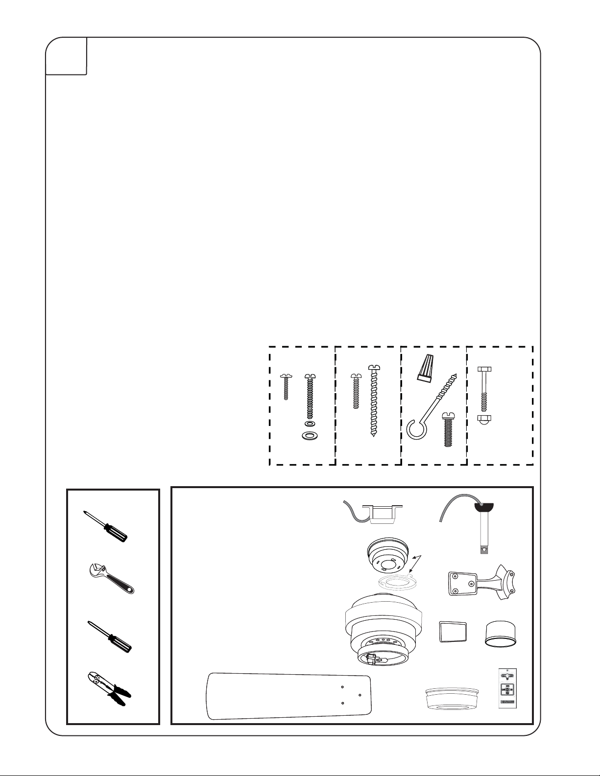
Screw Package
S1. Wood Screws & Washers
S2. Screws (for Canopy)
S3. Bracket Screws & Washers
S4. Blade Screws
S5. Motor Screws
S6. Wire Connectors
S7. Safety Bolt & Nut
S8. "J" Hook
S9. Zip Tie
Tools you Need
Parts
1. Mounting Bracket
2. Down Rod Assembly
1. Phillips Screwdriver
3. Adjustable Wrench
6" Rod Supplied
3. Canopy Assembly
4. Flange Cover
5. Fan Housing & Motor
6. Blade Arms
7. Blades
8. Medallion
9. Glass
10. TCS Hand Held Control
Quantity
2
Hardware
Inventory
3
2
16
11
3
1
1
1
What You Have
Quantity
S6
S4
S3
S2
S7
S1
S8
S5
1
1
1
1
1
1
5
5
5
1
1
5
3
8
2
6
4
2. Flat Screwdriver
4.Wire Strippers
7
9
10
Page 4
3
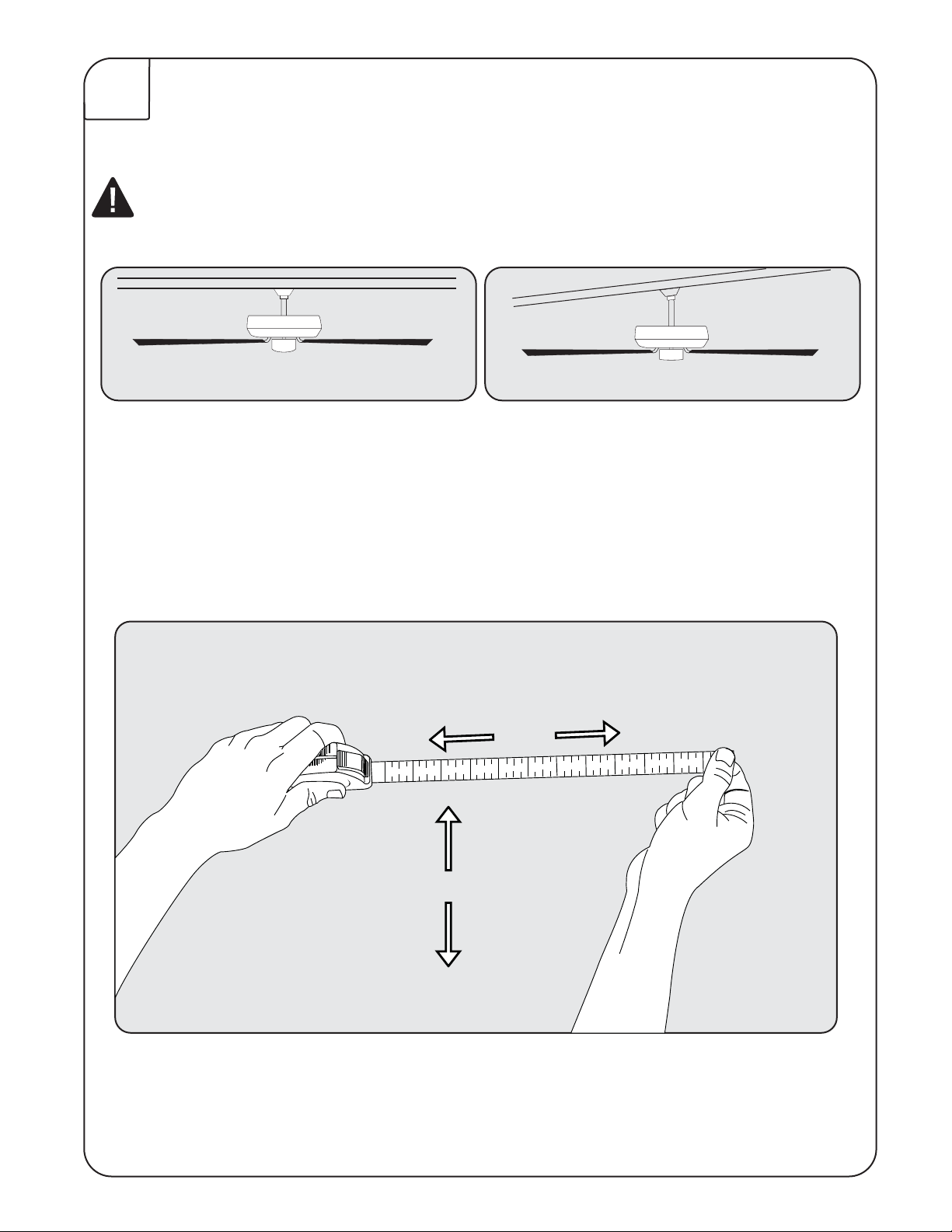
Turn off circuit breakers and wall switch to the fan supply line leads.
IMPORTANT: If using the angle mount method, check to make sure the ceiling angle is
not steeper than 35º. Angles greater than 35º will require a 45º angle adapter.
Preparation
B%PXOSPE.PVOU
/PSNBM$FJMJOHT
Important: When using an existing outlet box, be sure the box is
securely attached to the building structure and can support the full
weight of the fan. Failure to do so can result in serious injury or death.
b.) Angle Mount
7BVMUFE$FJMJOHT
30”
84”
t$IFDLUPNBLFTVSFCMBEFTBSFBUMFBTUwGSPNBOZPCTUSVDUJPO
t$IFDL%PXOSPE-FOHUIUPNBLFTVSFCMBEFTBSFBUMFBTUBCPWFUIFnPPS
Page 5
4
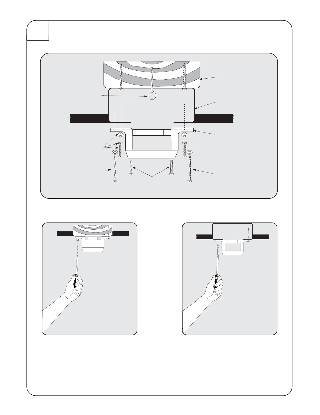
Installing Mounting Bracket
Support Beam
“J” Hook (S8)
Outlet Box (A)
Ceiling
Bracket Screws
& Washers (S3)
Wood Screws (S1)
OUTLET BOX
Mounting Bracket (1)
Wood Screws (S1)
Canopy Screws (S2)
NOTE: Do not mount directly to sheet rock or ceiling tile.
Prior to securing mounting bracket, screw "J" hook (S8) into ceiling outlet box
as a secondary support means. Secure mounting bracket (#1) to the outlet box
(A) by tightening bracket screws & washers (S3) as shown. If not mounting to
an outlet box, use wood screws (S1) and washers (S3) and mount securely to
ceiling beam. Be sure at this point to insert canopy screws (S2) in bracket.
Page 6
5
Downrod Assembly
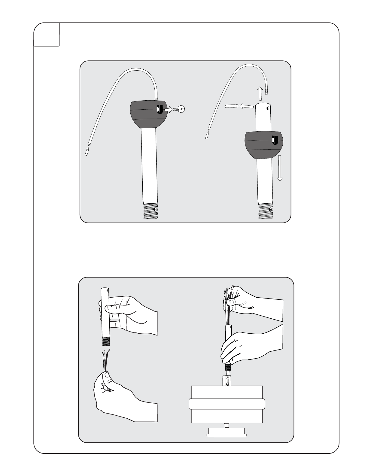
Locate downrod assembly (#2). Loosen ball screw on black hanging ball to
free lock pin. Black hanging ball will slide down. Remove ground screw and
green ground wire. Remove hanging ball from downrod and save all parts.
Insert fan wires through downrod.
Page 7
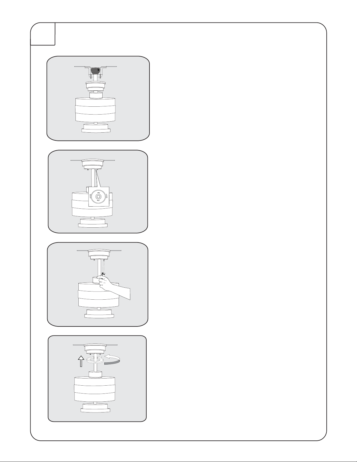
6
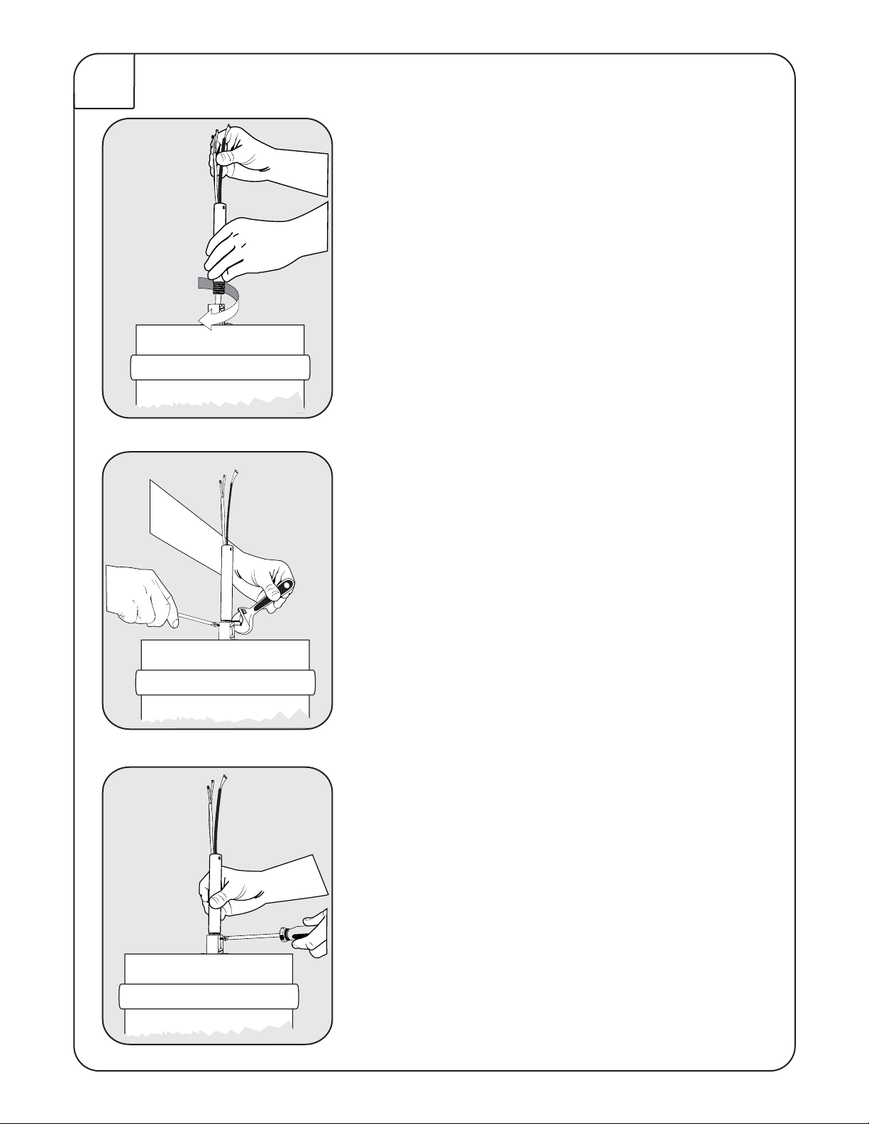
read the downrod onto the motor housing
making sure the wires don’t get twisted.
Insert saftey bolt (S7) through flange & downrod
and attach nut. Tighten firmly.
Tighten set screw (A) against downrod.
Page 8

7
Place Flange cover (4) over downrod
assembly. Place Canopy Assembly (3) over
downrod (2).
WARNING: Failure to completely tighten downrod as described in
steps above could result in the fan loosening and possibly falling.
Replace hanging ball, insert hanging pin through downrod and tighten set
screw "C" in hanging ball into downrod.
Page 9
8
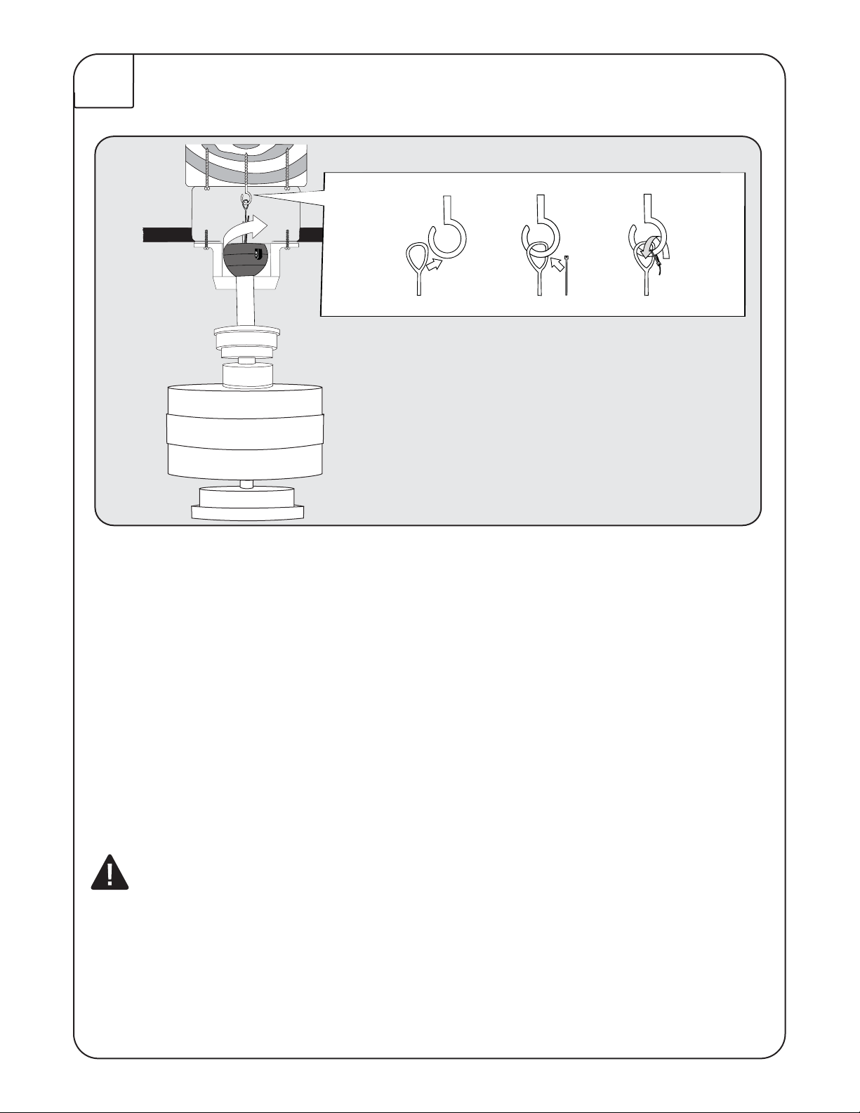
Lift fan onto the mounting bracket (#1). Turn housing until hanging ball seats
itself into ball socket (listen for click).
For added security, attach safety cable from fan unit to "J" hook (S8) in outlet
box. Secure by looping zip tie (S9) through safety cable and "J" hook. Tighten
zip tie securely.
WARNING: To reduce the risk of fire, electric shock or personal injury,
mount so outlet box marked "acceptable for fan support" and use mounting
screws provided with the outlet box. Most outlet boxes commonly used for
the support of lighting fixtures are not acceptable for fan support and may
need to be replaced. Consult a qualified electrician if in doubt.
Page 10
9
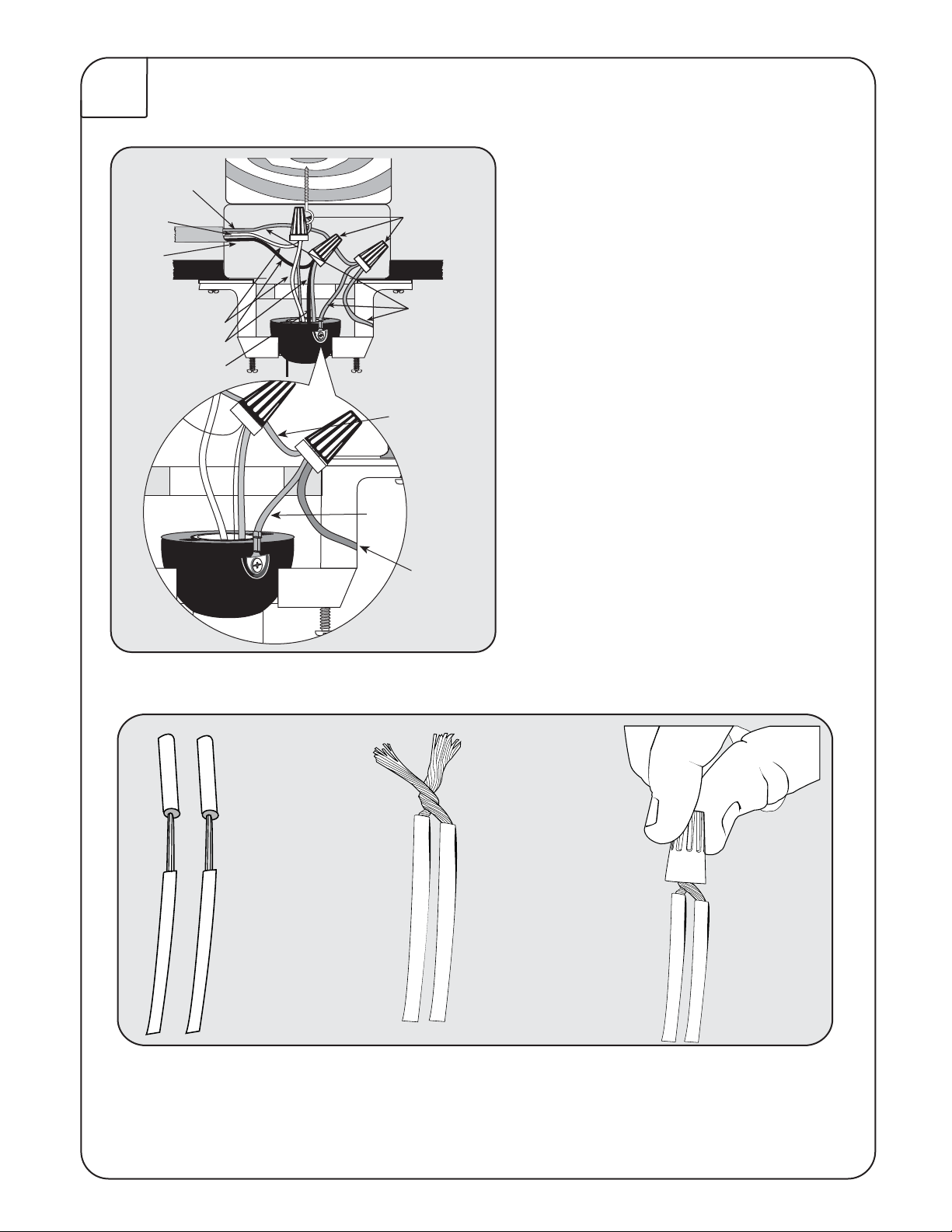
Ground
White (Neutral)
Black
(Power)
Wire
Connectors
(S6)
1. Connect fan wires to ceiling
wires: white fan wire to white
outlet wire, black to black and
green to green. Wire connectors
White
Black
Blue
Ground
(Green)
Outlet Box
Ground (Green)
Downrod
Ground
(Green)
Mounting Bracket
Ground (Green)
(S6) are provided for your convenience. If an additional blue wire is
present then also connect the blue
wire to the black wire.
2. After connections are made, turn
splices upward and push carefully
into outlet box. Separate blue and
black wires on one side of the box,
and white and green wires on the
other side.
ere are up to four wires coming from the
top of the motor (including ground wire).
Page 11
10
Attach canopy (3) to the mounting
bracket by placing screws (S2) into slot
in canopy.
Twist clockwise to lock into place.
Tighten screws firmly.
Seat the canopy screw cover into slots
and twist to lock.
Page 12
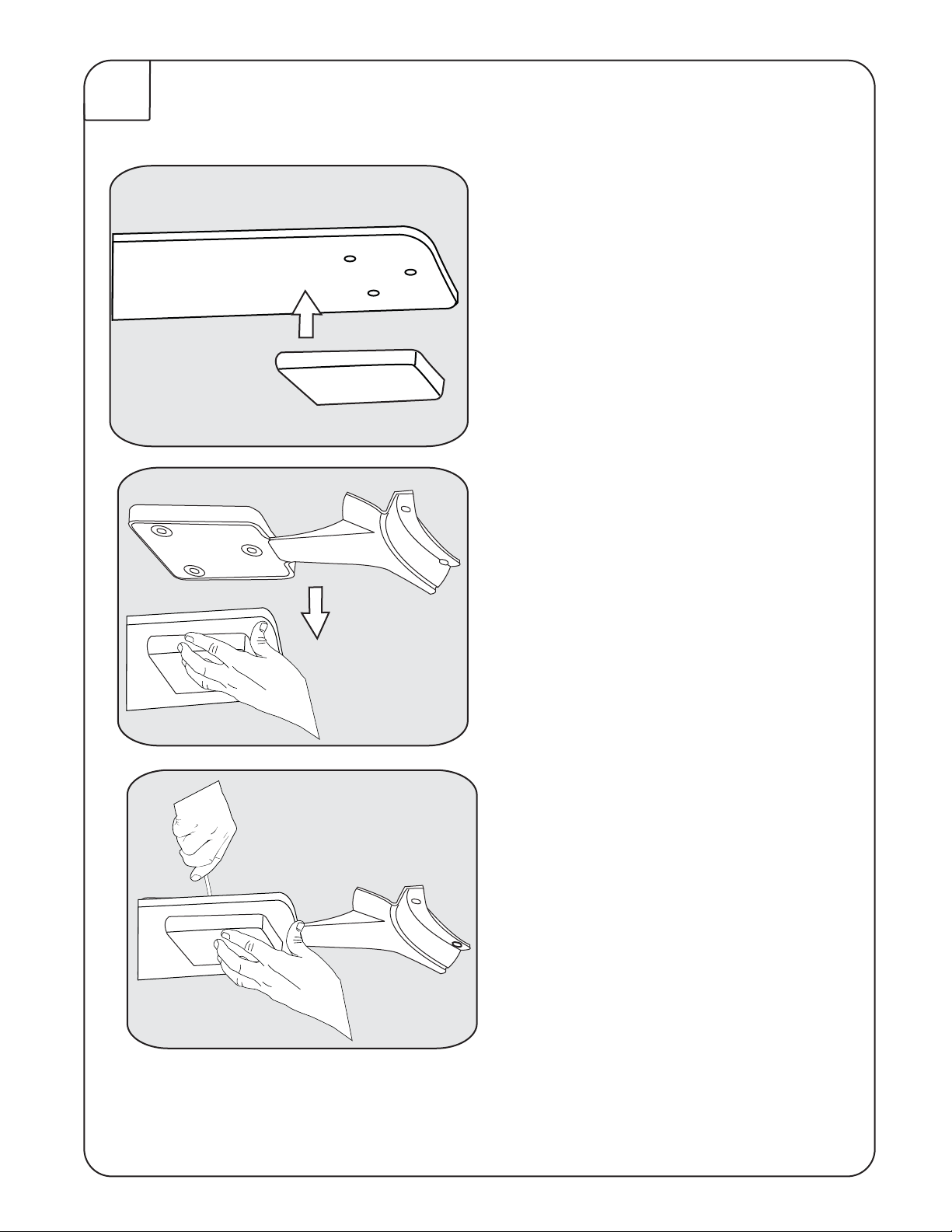
11
Assemble blade arm, blade and
Blade Arm Medallion.
Assemble blade arm, blade and Blade
Arm Medallion
.
Using motor screws (S5) provided, line up holes from the blade arm
with the holes in the motor housing. Tighten screws securely.
Page 13
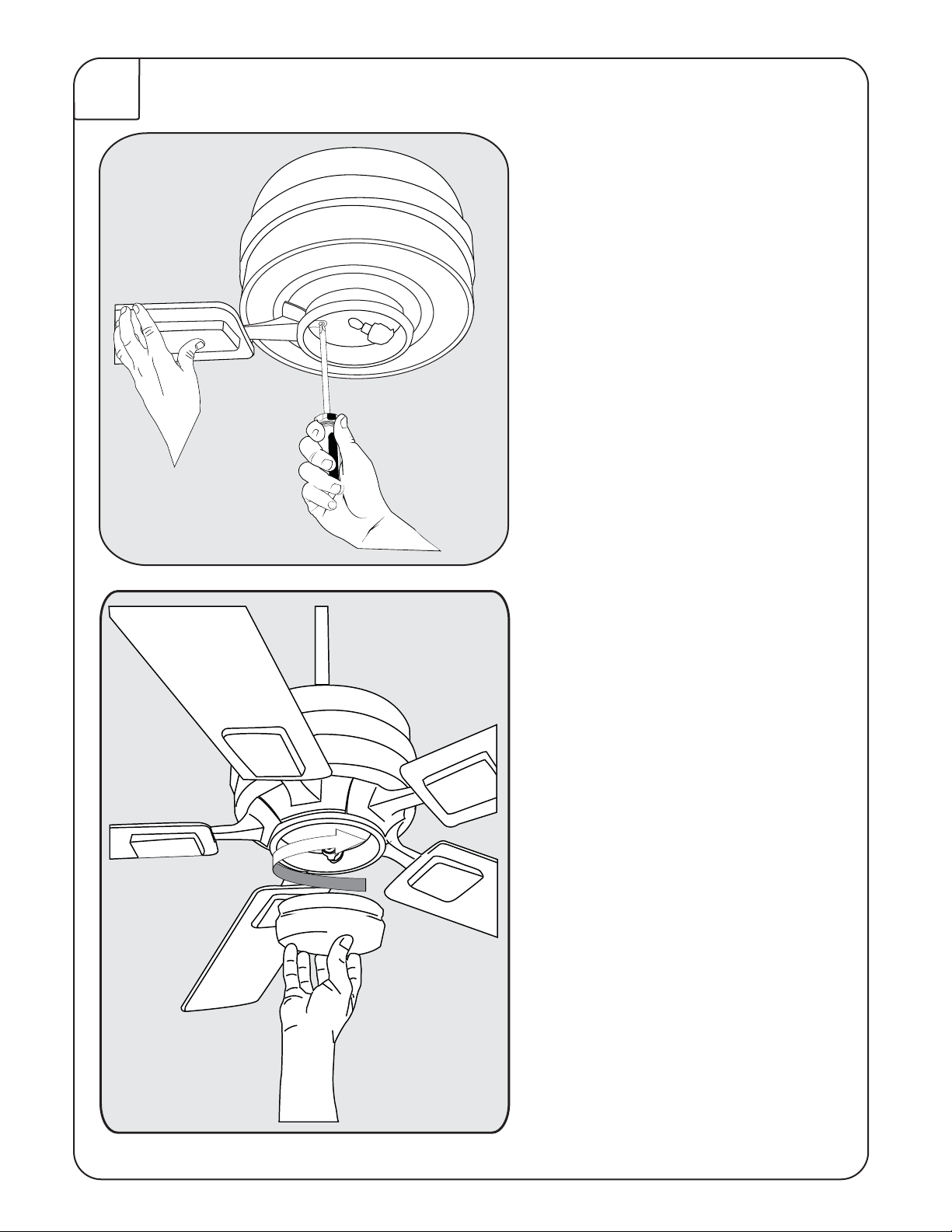
12
A slot (as shown in Step 12) allows
you to tighten the blade assembly to
the Fan Motor.
Screw in Halogen bulb (included).
Twist the Glass onto Light Kit
Fitter securely.
Page 14
Remote Control Operation Instructions
ON/OFF For emergency shut off.
HIGH Controls fan motor speed. To select desired speed, press
MEDIUM button once and release.
LOW
REVERSE Controls direction of fan blades. To reverse fan blades, press
once and release.
FAN OFF Turns fan motor speed off. Press once to turn off. To start
motor speed again, hit one of the motor speed buttons.
L-1 Controls no function on this fan.
L-2 Controls the on/off and intensity for optional light kit. Push
and release for on/off function. Hold down for full range light
dimming.
NOTE: The “High”, “Medium” or “Low” buttons may be used to start
the fan motor. The speed of the fan may be changed at anytime.
 Loading...