

OPERATION
Press the lighted push button to open or close the door.
Press again to reverse the door during the closing cycle
or to stop the door while it's opening.
Light Feature – Press the Light button to turn the opener
light on or off. It will not control the opener lights when the
door is in motion. If you turn it on and then activate the
opener, the light will remain on for 4-1/2 minutes. Press
again to turn it off sooner.
Lock Feature – Designed to prevent operation of the
door from hand-held remote controls. However, the
door will open and close from the Door Control, the
Outdoor Key Switch and the Keyless Entry
Accessories.
To activate – press and hold the Lock button for 2
seconds. The push button light will flash as long as the
Lock feature is on.
To turn off – press and hold the Lock button again for
2 seconds. The push button light will stop flashing. The
Lock feature will also turn off whenever the “learn” button
on the motor unit panel is activated.
Model 139.53687
Premium Control Console
114A2349B
Locate the door control within sight of the door at a minimum
height of 5 feet (1.52 m) where small children cannot reach, and
away from all moving parts of the door and door hardware.
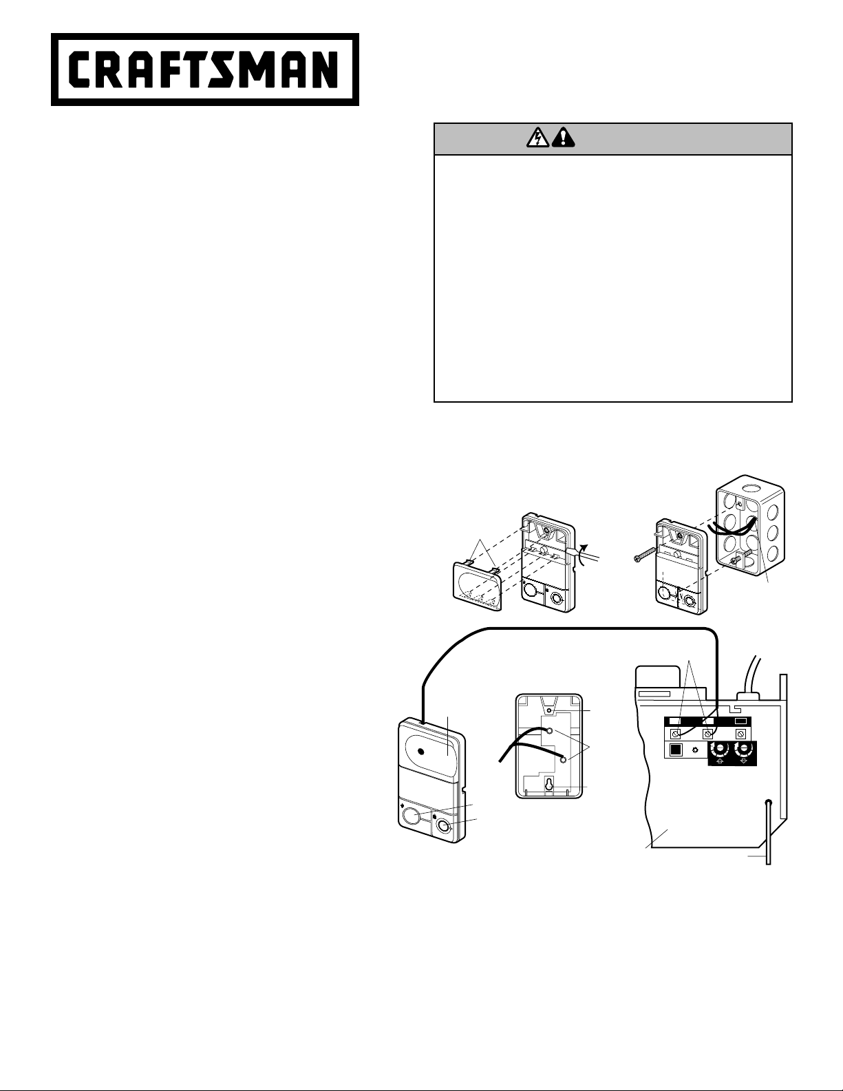
INSTALLATION
Remove the old Control Panel/Lighted Door Control Button.
The door control is typically attached directly to the wall. If
installing into drywall, drill 5/32" holes and use the anchors
provided. For pre-wired installations (as in new home
construction), Console models may be mounted to a standard
single gang box (Figure 2).
1. Strip 1/4" (6 mm) of insulation from one end of the bell wire
and connect it to the two screw terminals on the back of the
door control: white to 2, and white/red to 1.
2. Remove white cover by gently prying at slot in top of the cover
with a small flat head screwdriver. Fasten with 6ABx1-1/4"
self-tapping screws (drywall installation) or 6-32x1" machine
screws (into gang box) as follows:
• Install bottom screw, allowing 1/8" (3 mm) to protrude above
wall surface.
• Position bottom of door control on screw head and slide
down to secure. Adjust screw for snug fit.
• Drill and install top screw with care to avoid cracking plastic
housing. Do not overtighten.
• Insert top tabs and snap on cover.
3. (For standard installation only) Run the bell wire up the wall
and across the ceiling to the motor unit. Use insulated staples
to secure the wire in several places. Do not to pierce the wire
with a staple, creating a short.
4. Connect the bell wire to the terminal screws on the opener
panel: white to 2; white/red to 1.
5. Position the antenna wire as shown.
To prevent possible SERIOUS INJURY or DEATH from electrocution:
• Be sure power is not connected BEFORE installing door control.
• Connect ONLY to 24 VOLT low voltage wires.
To prevent possible SERIOUS INJURY or DEATH from a closing
garage door:
• Install door control within sight of garage door, out of reach of
children at a minimum height of 5 feet (1.52 m), and away from all
moving parts of door.
• NEVER permit children to operate or play with door control push
buttons or remote control transmitters.
• Activate door ONLY when it can be seen clearly, is properly adjusted,
and there are no obstructions to door travel.
• ALWAYS keep garage door in sight until completely closed. NEVER
permit anyone to cross path of closing garage door.
WARNING
USER INSTRUCTIONS
© 2006, Sears, Roebuck and Co., ® Registered Trademark / ™ Trademark / SMService Mark of Sears, Roebuck and Co.
® Marca Registrada / ™Marca de Fábrica /
SM
Marca de Servicio de Sears, Roebuck and Co.
®
To Replace,
Insert
Top Tabs
First
To Remove,
Twist
Here
REMOVE & REPLACE COVER
L
O
CK
LIG
H
T
PRE-WIRED
INSTALLATION
24 Volt
2-Conductor
Bell Wire
Light
Antenna
Back Panel
of Opener
Opener
Terminal Screws
KG
KG
1
3
9
7
5
1
3
9
7
5
2 3
1
L
O
C
K
L
G
I
H
T
2-Conductor
Bell Wire
Lock
Lighted
Push Button
PREMIUM CONTROL CONSOLE
Terminal
Screws
Top
Mounting
Hole
Bottom
Mounting
Hole
BACK VIEW
WHITE
2
RED
1
Figure 1 Figure 2
WARNING
Modelo 139.53687
La Consola De Control Premium
114A2349B
Ubique el control de la puerta de manera que quede a la vista desde la
puerta y a una altura mínima de 1.52 m (5 pies) donde los niños
pequeños no lo puedan alcanzar y lejos de las partes móviles de la
puerta y de la tornillería.
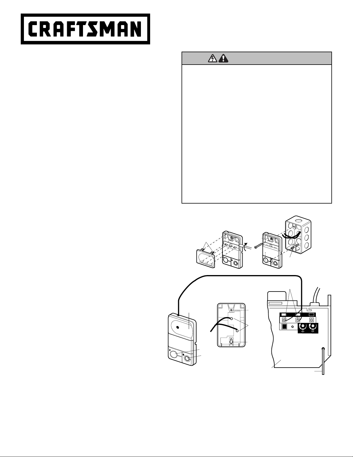
INSTALACIÓN
Quite la consola de control o el botòn de control iluminado que exisite. El
control de la puerta está generalmente instalado directamente en la
pared. Si se va a instalar en un muro falso, taladre dos orificios de 5/32
de pulg. y use los sujetadores que se incluyen. Para una instalación
precableada, (por ejemplo, en una casa en construcción) los modelos de
consola se pueden instalar en una caja múltiple estándar (Figura 2).
1. Pele 6 mm (1/4 de pulg.) del extremo del cable de campana y conéctelo
a las terminales de tornillo correspondientes al color del cable en la parte
posterior de la unidad de control de la puerta; blanco a 2 y blanco y
rojo a 1.
2. Con un destornillador abra la tapa por el costado. Sujete con un tornillo
autorroscante de 6AB por 1-1/4 pulgadas (instalación en muro falso) o
con un tornillo para metales de 6 -32 por 1 pulgadas (dentro de la caja
múltiple) como se indica a continuación:
• Instale el tornillo de la parte inferior de manera que sobresalga por lo
menos 3 mm (1/8 de pulg.) de la pared.
• Coloque la parte inferior de la unidad de control de la puerta sobre la
cabeza del tornillo y deslícelo para sujetarlo, vuelva a apreta el
tornillo para un ajuste firme.
• Taladre y coloque el tornillo de la parte superior con precaución de
no romper la cubierta plástica de la unidad.
No apriete en exceso.
• Inserte las lengüetas superiores y cierre la cubierta.
3. (Únicamente para las instalaciones estándar) Corra el cable de
campana al motor a lo largo de la pared y el techo; use grapas con
aislamiento en varios puntos a lo largo del cable para sujetarlo. Tenga
cuidado de no perforar el cable al engraparlo, creando así un corto
circuito o un circuito abierto.
4. Conecte el cable de campana a los tornillos terminales del panel de la
unidad del motor: blanco a dos; blanco y rojo a 1.
5. Coloque el cable de la antena como se indica.
OPERACIÓN
Oprima el botón iluminado para abrir o cerrar la puerta. Oprima de
nuevo para que la puerta retroceda en el ciclo de cierre o para
detener la puerta cuando se está abriendo.
Luz – Oprima el botón de Luz para encender o apagar la luz del
abridor. Este botón no controla las luces del abridor cuando la
puerta está en movimiento. Si usted enciende la luz y luego activa
el abridor, la luz permanecerá encendida durante cuatro minutos y
medio. Oprima el botón nuevamente para que la luz se apague
antes.
Seguro – Esta función está diseñada para evitar la operación de
la puerta con los controles remotos manuales. No obstante,
la puerta se puede abrir y cerrar con los siguientes
accesorios: el Control de la puerta, el Interruptor de llave
externo, y la Entrada sin llave.
Para activar – esta función, oprima y mantenga oprimido el botón del
seguro (Lock) por dos segundos. La luz del botón va a parpadearán
mientras esté activado el seguro.
Para desactivar – la función, oprima y mantenga oprimido el botón
del seguro por dos segundos. La luz del botón dejará de parpadear.
La función del seguro también se apaga siempre que el botón
“aprender” del panel del motor esté activado.
®
Para evitar la posibilidad de una LESIÓN GRAVE o INCLUSO LA
MUERTE por electrocución:
• ANTES de instalar el control de la puerta, cerciórese de que la
energía eléctrica no esté conectada.
• Conecte el control SÓLO a cables de bajo voltaje de 24 VOLTIOS.
Para evitar la posibilidad de una LESIÓN grave e incluso LA MUERTE
cuando la puerta de la cochera se está cerrando:
• Instale el control de la puerta de manera que quede a la vista desde la
puerta de la cochera, fuera del alcance de los niños a una altura
mínima de 1.52 m (5 pies), y alejado de las partes móviles de la
puerta.
• NUNCA permita que los niños hagan funcionar o jueguen con los
botones de control de la puerta ni con los transmisores de control
remoto.
• Haga funcionar la puerta SÓLO si la puede ver claramente, si la
puerta está debidamente ajustada, y si no no hay ninguna
obstrucción en su recorrido.
• SIEMPRE tenga a la vista la puerta de la cochera hasta que esté
completamente cerrada. NUNCA permita que alguien se atraviese en
el recorrido de la puerta de la cochera cuando se está cerrando.
AADVERTENCIA
ADVERTENCIAADVERTENCIA
INSTRUCCIONES DEL USUARIO
© 2006, Sears, Roebuck and Co., ® Registered Trademark / ™ Trademark / SMService Mark of Sears, Roebuck and Co.
® Marca Registrada / ™Marca de Fábrica /
SM
Marca de Servicio de Sears, Roebuck and Co.
KG
KG
1
3
9
7
5
1
3
9
7
5
2 3
1
L
O
C
K
L
G
I
H
T
WHITE
2
RED
1
Seguro
Luz
Botón con luz
Cable de campana
de dos conductores
(VISTA POSTERIOR)
Orificio
inferior
de montaje
Antena
Tornillos terminales
del abridor
Orificio
superior
de montaje
Tornillos
terminales
CONSOLA DE CONTROL PREMIUM
Panel posterior
del abridor
Para volver a ponerla,
primero inserte
las lengüetas
superiores
Para quitar,
doble
aquí
INSTALACIÓN PRE-CABLEADA
QUITAR Y VOLVER A
PONER LA TAPA
L
O
C
K
LI
G
H
T
Figura 1
Figura 2
Cable de campana de
24 voltios de dos conductores
ADVERTENCI
 Loading...