

CPT CLAA370WF02S Specification

Chhuunngghh
C
waa
w
Piiccttuurree TTuubbeess,, LLttdd..
P
TTeecchhnniiccaall S
To : HUI YING TUNG ELECTRONIC CO., LTD
Date : 2008.04.24
Sppeecciiffiiccaattiioonn
CPT TFT-LCD
CLAA370WF02 SY
ACCEPTED BY:
APPROVED BY CHECKED BY PREPARED BY
Product Planning
Neptune
Product Planning Management General Division
CHUNGHWA PICTUER TUBES, LTD.
溫文良
Management
General Division
1127 Hopin Rd., Padeh, Taoyuan, Taiwan 334, R.O.C.
TEL: +886-3-3675151 FAX: +886-3-377-3001
Doc. No: CLAA370WF02_SY-HUI YING TUNG-SPEC-20080424 Issue Date: 2008/04/24
CPT CHUNGHWA PICTURES TUBES, LTD.,
RECORD OF REVISIONS
Revision No. Date Page Description
Ver 1.0 2007/07/30 --
Writing Modify
CPT Confidential
2/25
CLAA370WF02_SY-HUI YING TUNG-SPEC-20080424
CPT CHUNGHWA PICTURES TUBES, LTD.,
CONTENTS
No Item Page
1 OVERVIEW 4
2 ABSOLUTE MAXIMUM RATINGS 5
3 ELECTRICAL CHARACTERISTICS 6
INTERFACE PIN CONNECTION
4
5 INTERFACE TIMING 14
6 BLOCK DIAGRAM 16
7 MECHANICAL SPECIFICATION 17
8 OPTICAL CHARACTERISTICS 19
9 RELIABILITY TEST CONDITIONS 22
10 HANDLING PRECAUTIONS FOR TFT-LCD MODULE 23
10
CPT Confidential
3/25
CLAA370WF02_SY-HUI YING TUNG-SPEC-20080424
CPT CHUNGHWA PICTURES TUBES, LTD.,
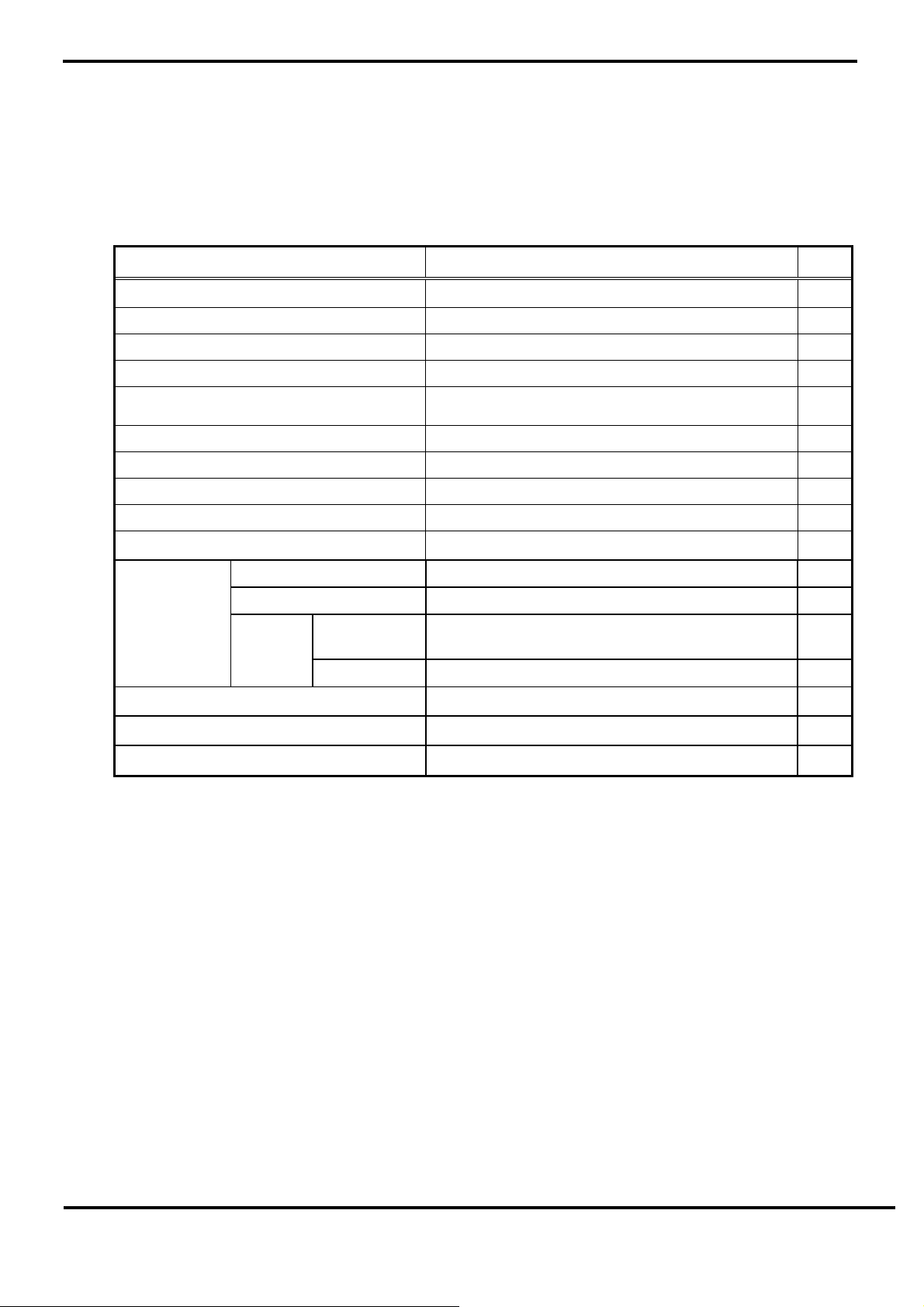
1. OVERVIEW
CLAA370WF02 S
Display) module composed of LCD panel, LVDS driver ICs, control circuit and backlight. By
applying 8 bit digital data, 1366*768, 16.7 million-color images are displayed on the 37”
diagonal screen. Inverter for backlight is included in this module. General specifications are
summarized in the following table:
Display Area 819.6(H) × 460.8(V) (37.02 inch diagonal) mm
Number of Pixels 1366(H) × 768(V) 16:9
Bezel Opening Area 827.8 x 469.4 mm
Color Pixel Arrangement RGB Vertical Strip
Display Mode Normally Black
Number of Colors 16.7M (8bits) color
Wide View Tech. E-MVA
Electrical Interface LVDS
Total Module Power 130 (Typ.) W
is 37” color (94.03cm) TFT-LCD (Thin Film Transistor Liquid Crystal
Item Specification Unit
Pixel Pitch 0.6(H) × 0.6(V) mm
Horizontal(H) 877 ( Typ) mm
Module
Outline
Dimension
Module Weight 10000 (Typ) g
Surface Treatment Hard coating, Surface-hardness: 3H
Depth(D)
Backlight Unit CCFL, 16 tubes
Vertical(V) 514.6 (Typ) mm
without
inverter
with inverter 55.3 (Typ) mm
45.1(Typ) mm
2. ABSOLUTE MAXIMUM RATINGS
CPT Confidential
4/25
CLAA370WF02_SY-HUI YING TUNG-SPEC-20080424
CPT CHUNGHWA PICTURES TUBES, LTD.,
p
]
The following are maximum values which, if exceeded, may cause faulty operation or
damage to the Unit.
Item Symbol Min. Max. Unit Note
Power Supply Voltage For LCD VCC -0.3 14.0 V
Input voltage of inverter VBL -0.3 27 V
Inverter dimming VDIM -0.3 3.5 Vdc
Backlight on/off
VBLON -0.3 5.5 Vdc
ESD for Connector VESD -250 250 V
ESD for Module
Operation Ambient
Storage Temperature
VESD -15 15 KV
Top
stg -20 60 ℃ *1) *2)
T
0 50 ℃ *1) *2) *3)
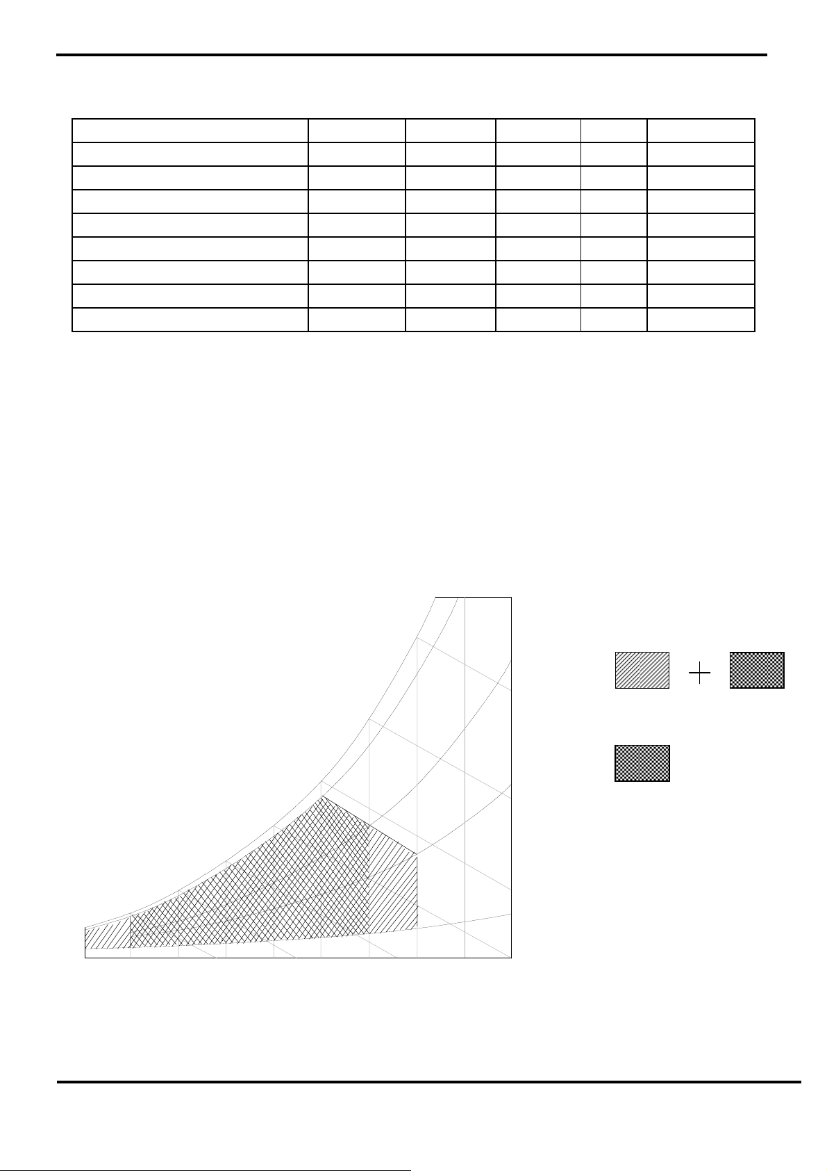
[Note 1] The relative temperature and humidity range are as below sketch
Humidity≦85%RH without condensation .Relative
Humidity ≦90% (Ta≦ 40℃) , Wet Bulb Temperature ≦39℃(Ta≧40℃)
[Note 2] If you use the product in an environment which’s over the definition of temperature
and humidity too long , it will effect the result of visual inspection.
[Note 3] If you operate the product in normal temperature range, the center surface of panel
should be under 60℃
90%
60
60%
Wet Bulb
erature [C
Te m
50
Storage
40
30
40%
Operation
10
0
20
Humidity [(%)RH]
10%
CPT Confidential
0 -20
10 20 30 40 50 60 70
Dry Bulb Temperature [C]
5/25
CLAA370WF02_SY-HUI YING TUNG-SPEC-20080424
80
CPT CHUNGHWA PICTURES TUBES, LTD.,
3. ELECTRICAL CHARACTERISTICS
3.1 TFT-LCD MODULE
Item Symbol Min. Typ. Max. Unit Note
LCD Power Supply Voltage VCC
Ripple Voltage Vrpd
Rush current I rush
White
LCD Power
Supply Current
Black
ICC
RGB stripe
LCD power consumption Pc
High input voltage of LVDS V
Low input voltage of LVDS V
IN+
IN-
Input common voltage of LVDS VCM
Input terminal resistor of LVDS R
T
10.8 12.0 13.2
-- -- 100
mVp-p VCC=+12.0V
-- -- 4
-- 715
-- 428
--
-- 678
-- 10 12
-- -- 100
100 -- --
-- 1.25 -
-- 100 --
V *1)
A *2)
*3) *3)
W
mV
mV
V
ohm
[Note]
Ta= 2 5℃
*4)
*5)
*1) The module should be always operated within above ranges.
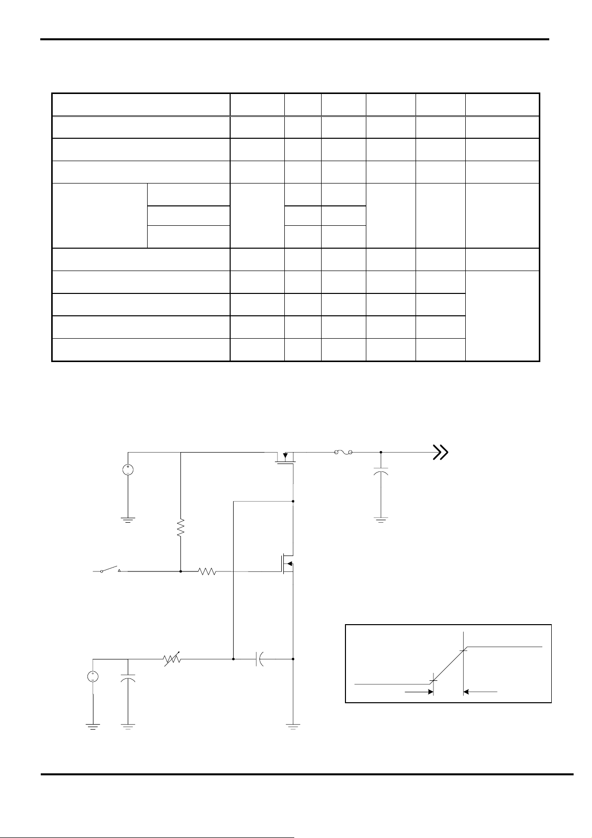
*2) Measure conditions:
(High to low)
DC
+15V
DC
+12V
SW
(control
signal)
C1
1uF
VR1
47k
Q1
2SK1475
R1
47k
2SK1470
R2
1k
C2
0.01uF
FUSE
Q2
GND
C3
1uF
0.1Vcc
VCC
LCD Module
Input
+12V
0.9Vcc
1ms
CPT Confidential
6/25
Vcc rising time is 0.5 ms
CLAA370WF02_SY-HUI YING TUNG-SPEC-20080424
CPT CHUNGHWA PICTURES TUBES, LTD.,
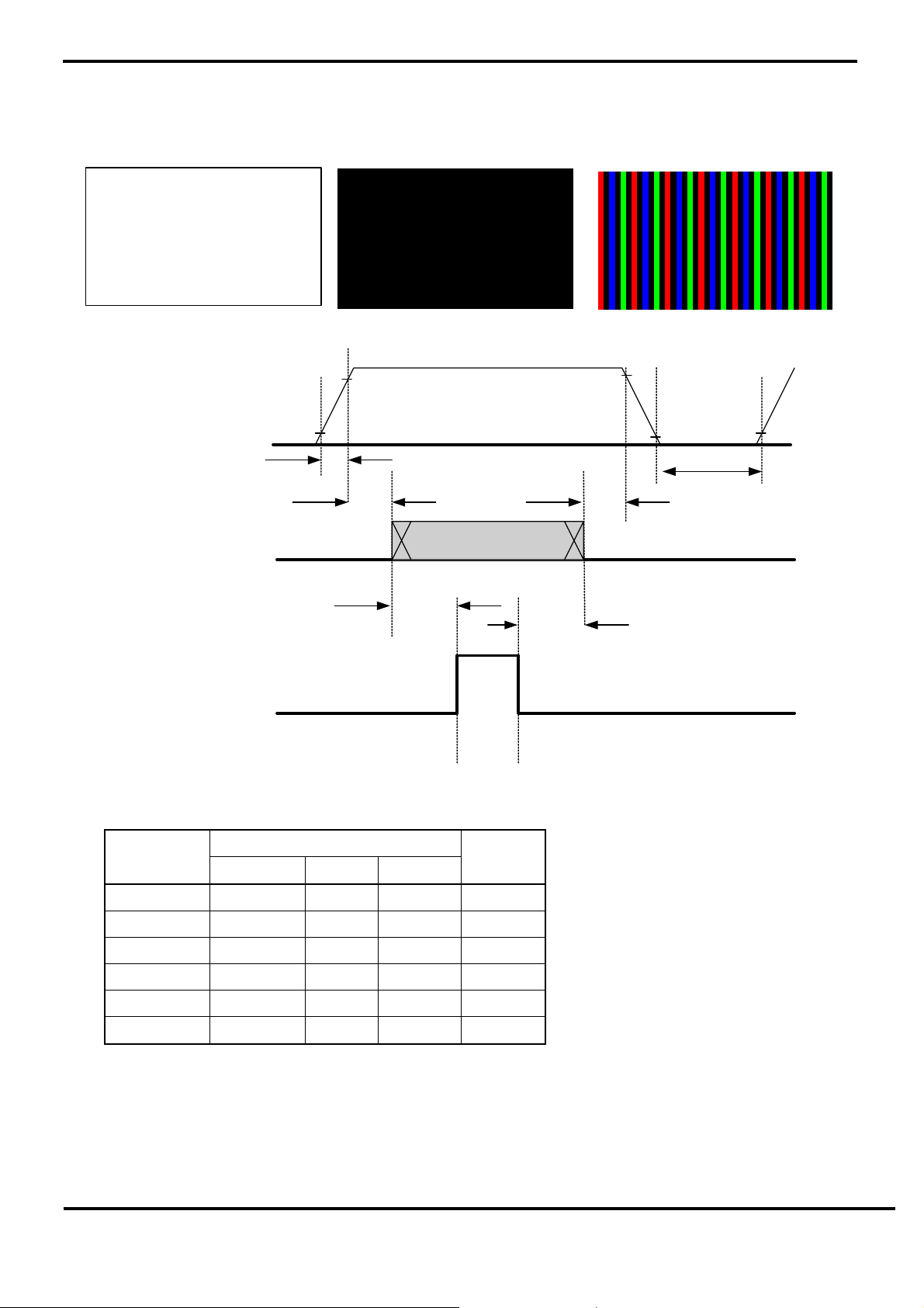
*3) The specified power supply current is under condition at Vcc=12V, Ta=25+/-2℃, f
=60Hz,
v
whereas a power dissipation check pattern below is displayed.
a. White pattern b. Black pattern c. RGB Stripe pattern
*4) Power and Signal Sequence:
VCC:12V
90%
10%
Power Supply
(VCC:12V)
90%
10%
T1 T4
Interface Signal
(LVDS Data with H,Vsync
and DE)
Power Supply for
Backlight
Power Sequence Table
Parameter
T1 0.5 --- 30 ms
T2 0 --- 50 ms
T3 0 --- 50 ms
T4 2000 --- ms
T2 T3
T5
T6
BL on
Value
Unit
Min Typ Max
T5 110 --- ms
T6 100 --- ms
Notes:
Please avoid floating state of interface signal at invalid period.
When the interface signal is invalid, be sure to pull down the power supply for LCD to 0V.
Lamp power must be turn off after power supply for LCD interface signal valid.
CPT Confidential
7/25
CLAA370WF02_SY-HUI YING TUNG-SPEC-20080424
CPT CHUNGHWA PICTURES TUBES, LTD.,
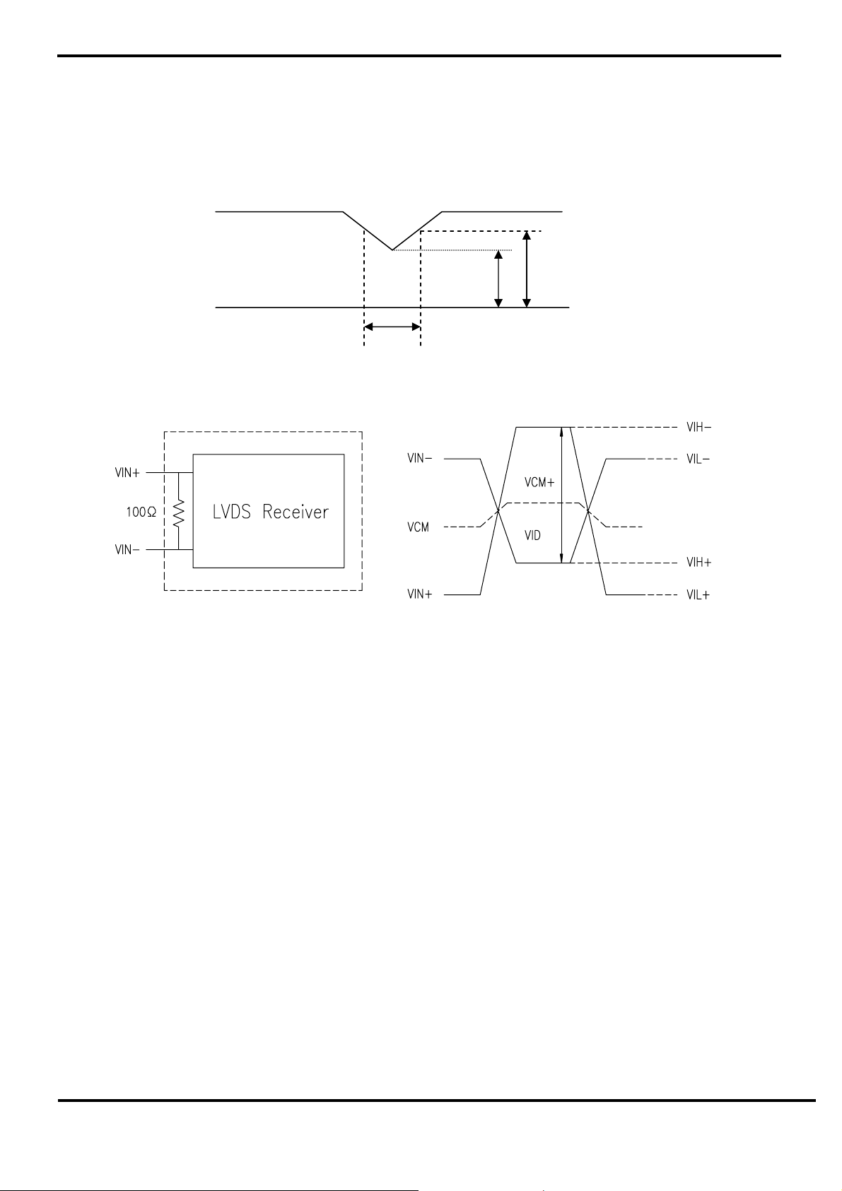
VCC-dip State:
1) When 9V VCC≦ <10.8 V, td 10 ms.≦
2) VCC>10.8V, VCC-dip condition should also follow the VCC-turn-off condition.
9V 10.8V
VCC
*5) LVDS Signal Definition:
RT
VID = VIN
VCM = △ |VCM
VID = △ |VID
– VIN-,
+
–VID-|,
+
+
td
–VCM-|,
VID+ = |VIH
VID- = |VIL+–VIL-|,
VCM = ( VIN
VCM+ = ( VIH++VIH- ) / 2,
VCM- =( VIL++VIL- ) / 2,
VIN+: Positive Polarity differential DATA & CLK input
VIN-: Negative Polarity differential DATA & CLK input
CPT Confidential
–VIH-|,
+
+VIN- ) / 2,
+
8/25
CLAA370WF02_SY-HUI YING TUNG-SPEC-20080424
 Loading...