

CPT CLAA215FA01A Specification

Global LCD Panel Exchange Center
www.panelook.com
Chhuunngghh
C
TTeecchhnniiccaallSSppeecciiffiiccaattiioon
waaPPiiccttuurreeTTuubbeess,,LLttdd..
w
n
To :
Date :
2010/02/09
CPT TFT-LCD
CLAA 215FA01A
ACCEPTED BYΚ
Doc. No: CLAA215FA01A Issue Date: 2010/02/09
APPROVED BY CHECKED BY PREPARED BY
Product Planning
Kevin Chen Lawrence Lai
Prepared by: Design Division
CHUNGHWA PICTUER TUBES, LTD.
No. 1, Huaying Rd., Sanho Tsun, Lungtan Shiang, Taoyuan, Taiwan, 325, R.O.C.
TEL: +886-3-3675151 FAX: +886-3-3773003
Management
Division
One step solution for LCD / PDP / OLED panel application: Datasheet, inventory and accessory!
www.panelook.com
Global LCD Panel Exchange Center
ʳ ʳ ʳ ʳ ʳ ʳ ʳ ʳ ʳ ʳ ʳ ʳ ʳ ʳ
www.panelook.com
CPT Disallow Disclosure, Reproduction or Distribution
Table of Content
NO Table of Content Note
1 OVERVIEW P.4
2 ABSOLUTE MAXIMUM RATINGS P.5
3 ELECTRICAL CHARACTERISTICS P.6
4 INTERFACE PIN CONNECTION P.12
5 INTERFACE TIMING P.14
6 BLOCK DIAGRAM P.17
7 MECHANICAL SPECIFICATION P.18
8 OPTICAL CHARACTERISTICS P.20
9 RELIABILITY TEST CONDITIONS P.23
10 DESIGNATION OF LOT MARK P.25
11 PACKING SPECIFICATION P.27
12 HANDLING PRECAUTIONS FOR TFT-LCD MODULE P.29
CPT Confidential and Property
ʳ
2/30
One step solution for LCD / PDP / OLED panel application: Datasheet, inventory and accessory!
www.panelook.com
Global LCD Panel Exchange Center
ʳ ʳ ʳ ʳ ʳ ʳ ʳ ʳ ʳ ʳ ʳ ʳ ʳ ʳ
www.panelook.com
CPT Disallow Disclosure, Reproduction or Distribution
1. OVERVIEW
CLAA215FA01A is 21.5” color TFT-LCD (Thin Film Transistor Liquid Crystal Display) module
composed of LCD panel, driver ICs, control circuit and backlight. By applying 6 bit digital data,
1920×1080, 16.7M-color images are displayed on the 21.5” diagonal screen. Input power voltage is 5.0V
for LCD driving. Inverter for backlight is not included in this module. General specification is
summarized in the following table:
ITEM SPECIFICATION
Display Area(mm) 476.64 (H) × 268.11 (V) (21.53-inch diagonal)
Number of Pixels 1920 (H) × 1080(V)
Pixel Pitch(mm) 0.24825 (H) × 0.24825 (V)
Color Pixel Arrangement RGB vertical stripe
Display Mode Normally white, TN
Number of Colors 16.7M(6bits+Hi-FRC)
Brightness(cd/m^2) 300cd/m2 (Typ.)(center, 7.5mA)
Viewing Angle(H/V) 170/160 (Typ.)
Surface Treatment Glare type
Power consumption(W) 30.0(Typ.) (w/o Inverter)
Module Size(mm) 495.6 (W) × 292.2 (H) ×16.35 (D) (Typ.)
Module Weight(g) 2600 (Typ.)
Backlight Unit CCFL, 4 tubes(top × 2/bottom × 2) , Edge light
CPT Confidential and Property
One step solution for LCD / PDP / OLED panel application: Datasheet, inventory and accessory!
ʳ
3/30
www.panelook.com
Global LCD Panel Exchange Center
ʳ ʳ ʳ ʳ ʳ ʳ ʳ ʳ ʳ ʳ ʳ ʳ ʳ ʳ
www.panelook.com
CPT Disallow Disclosure, Reproduction or Distribution
2. ABSOLUTE MAXIMUM RATINGS
ITEM SYMBOL MIN. MAX. UNIT REMARK
Power Supply Voltage for LCD VCC 0 6 V
Lamp Voltage VL 780 930 Vrms
Lamp Current ILO 3 8 mArms
Lamp Frequency FL 40 80 kHz
static electricity
VESDt -200 200 V
VESDc -8000 8000 V
*5)
Operation Temperature Top 0 50 к *1). 2). 3). 6)
Storage Temperature Tstg -20 60 к *1). 2). 3)
Delayed Discharge Time TD -- 1 sec *8)
[Note]
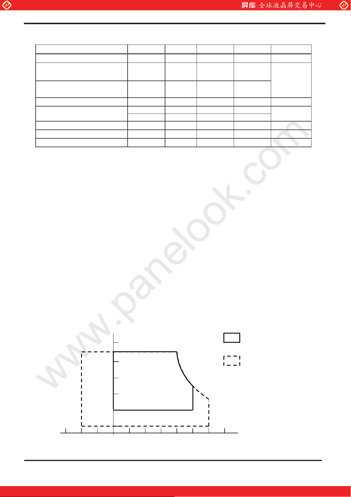
1).The relative temperature and humidity range are as below sketch, 90%RHMax.(TaЉ40к).
2).The maximum wet bulb temperature 39 (TaЉк Ї40 ) and without dewing.к
3).If you use the product in an environment which over the definition of temperature and humidity too
long to effect the result of eye-etching.
4).The life time of the lamp is related to the current of the lamp, so please according to the description
of the “(b) backlight” on page 7.
5).Test Condition: IEC 1000-4-2 VESDt: Contact discharge to input connector; VESD
: Contact
C
discharge to module
6).If you operate the product in normal temperature range, the center surface of panel should be under
50к.
7).When lamp current is out of the absolute maximum range, the life will fall rapidly or shown
unusual sign.
IL min 2mA only for test only, but we can’t guarantee the lifetime and performance.
8).Delay lighting testing needs the volt above start voltage Vrms. Before the procedure tube needs
typical lighting for 1 minute and stay in the temperature 25±2к for 24 hours and then testing in the
same condition in dark room.
Relative humidity(%RH)
90
Operating Range
80
Storage Range
60
40
20
5
0 20 40 60
-20
CPT Confidential and Property
One step solution for LCD / PDP / OLED panel application: Datasheet, inventory and accessory!
ʳ
Temperature (°C)
50
4/30
www.panelook.com
Global LCD Panel Exchange Center
ʳ ʳ ʳ ʳ ʳ ʳ ʳ ʳ ʳ ʳ ʳ ʳ ʳ ʳ
www.panelook.com
CPT Disallow Disclosure, Reproduction or Distribution
3. ELECTRICAL CHARACTERISTICS
(1).TFT-LCD
Ta=25к
ITEM SYMBOL MIN TYP MAX UNIT REMARK
Power Supply Voltage for LCD
Power Supply Current for LCD
Permissive Ripple Voltage for Logic
Differential Resistance
VCC 4.5 5.0 5.5 V *1)
ICC -- 1000 1500 mA *2)
VRP -- -- 100 mVp-p VCC=5.0V
Zm 90 100 110
The same motion input Voltage VCM
LVDS:
IN+ΔIN-
LCD Irush Current
Power consumption
[Note]
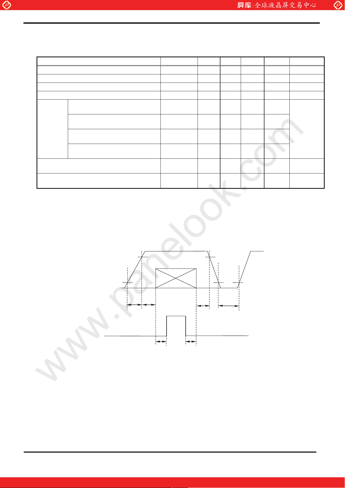
*1)PowerΕdata sequence
Differential input Voltage ΨVIDΨ
High electric potential threshold
voltage
Low electric potential threshold
voltage
VTH
VTL
Irush - - 4 A *4)
P - 5 7.5 W *2)
0.50msЉt1Љ10ms t4Њ1 sec
1.125 1.25 1.375 V
250 350 450 mV
*3)
- - 100 mV
-100 - - mV
0.01msІt2Љ50ms t5Њ200ms
0.01msІt3Љ50ms t6Њ200ms
LCD Power Supply
Logic Signal㩷
0.5V
Backlight Power Supply
4.5V
t2
t1
Data: RGB DATA, DCLK, DENA
Vin=5.0V
data
VL
t5 t6
4.5V
0.5V
t3
t4
0.5V
CPT Confidential and Property
One step solution for LCD / PDP / OLED panel application: Datasheet, inventory and accessory!
ʳ
5/30
www.panelook.com
Global LCD Panel Exchange Center
ʳ ʳ ʳ ʳ ʳ ʳ ʳ ʳ ʳ ʳ ʳ ʳ ʳ ʳ
www.panelook.com
CPT Disallow Disclosure, Reproduction or Distribution
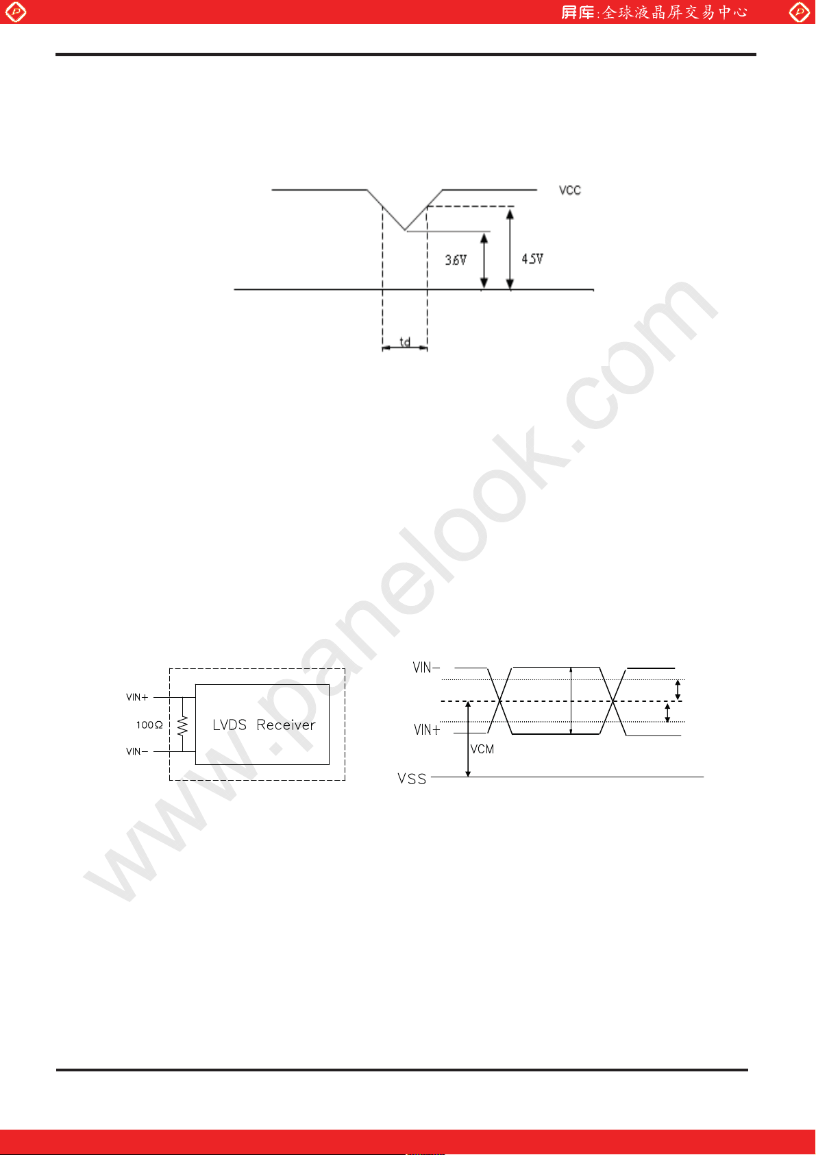
VCC-dip conditions:
(1) When 3.6VЉVcc(min)<4.5V: tdЉ10 ms
(2) When Vcc <3.6 V, VCC-dip conditions should also follow the VCC-turn-on conditions.
Typical value is measured when displaying horizontal gray scale line pattern:
2).
64 gray level, 1920 line mode
VCC=5.0 VΔfH= 66.9 kHzΔfV=60 HzΔfCLK=77 MHz
*
3) LVDS Signal definition
ΨVIDΨ
V
V
TH
TL
VIN+ΚPositive differential DATA & CLK Input
VIN-Κ Negative differential DATA ϟ CLK Input
CPT Confidential and Property
One step solution for LCD / PDP / OLED panel application: Datasheet, inventory and accessory!
ʳ
6/30
www.panelook.com
Global LCD Panel Exchange Center
ʳ ʳ ʳ ʳ ʳ ʳ ʳ ʳ ʳ ʳ ʳ ʳ ʳ ʳ
www.panelook.com
CPT Disallow Disclosure, Reproduction or Distribution
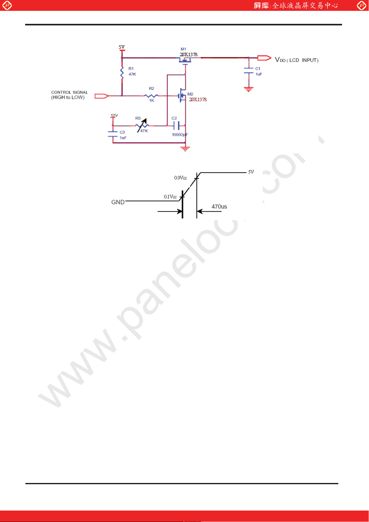
*4).Irush Measurement Condition
CPT Confidential and Property
One step solution for LCD / PDP / OLED panel application: Datasheet, inventory and accessory!
ʳ
7/30
www.panelook.com
Global LCD Panel Exchange Center
ʳ ʳ ʳ ʳ ʳ ʳ ʳ ʳ ʳ ʳ ʳ ʳ ʳ ʳ
www.panelook.com
CPT Disallow Disclosure, Reproduction or Distribution
(2).Backlight
1. Electrical specification
ITEM SYMBOL MIN TYP MAX UNIT REMARK
B/L Voltage VL 738 820 858 Vrms
B/L Current IL 7.0 7.5 8.0 mArms
B/L operating current ILO 3 7.5 8.0 mArms
B/L power consumption WL
Ё
23.4 26.6 W
Inverter Frequency FI 40 50 60 kHz
VS
ЁЁ
1770 Vrms Ta=0к
IL=7.5mA
Ta=25к
*1) Ta=25к
*1) Ta=25к
IL=7.5mA
Ta=25к
*2) Ta=25к
Starting Lamp Voltage
VS
ЁЁ
1530 Vrms Ta=25к
2. Lamp life time
ITEM
ILO at 3.0 mA ILO at 7.5 mA ILO at 8.0 mA
UNIT REMARK
Lamp life time Min. 50,000 Min. 40,000 Min. 35,000 Hr
Rated time
(turn on/off)
Ё
Min.100,000
Ё
time *4)
[Note] Inverter vendor: Sumida, model: TWS-400-9656
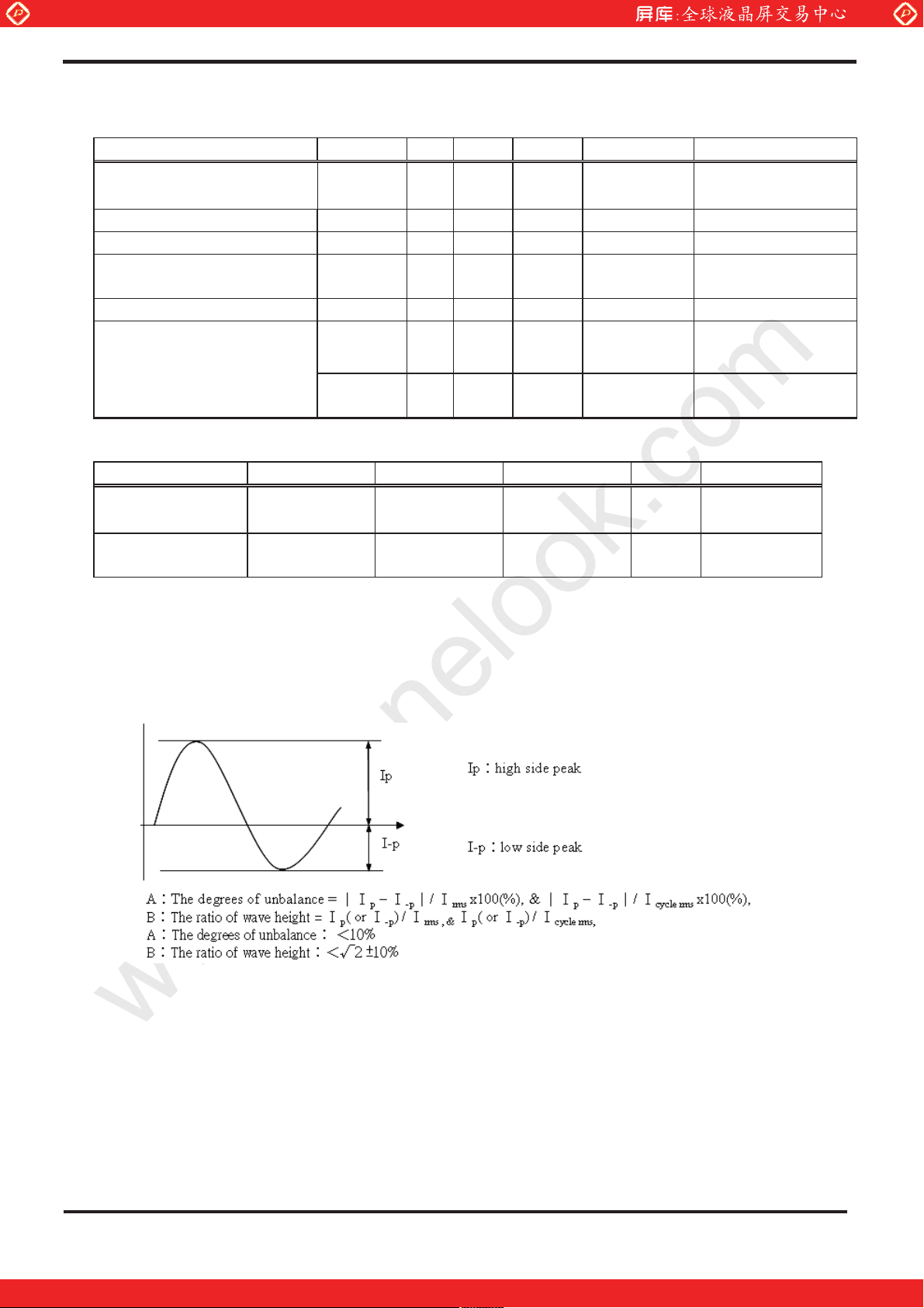
1) If the waveform of light up-driving is asymmetric, the distribution of mercury inside the lamp
tube will become unequally or will deplete the Ar gas in it. Then it may cause the abnormal
phenomenon of lighting-up. Therefore, designers have to try their best to fulfill the conditions
under the inverter designing-stage as below:
2) The lamp working current (I
of lamp typical current.(I
) of any waveform of light up-driving can not over the maximum
cyc
Cycle RMS of oscilloscope)
cyc :
*The property of single lamp
*Measure system: connector current meter with low voltage end
CPT Confidential and Property
One step solution for LCD / PDP / OLED panel application: Datasheet, inventory and accessory!
ʳ
8/30
www.panelook.com
Global LCD Panel Exchange Center
ʳ ʳ ʳ ʳ ʳ ʳ ʳ ʳ ʳ ʳ ʳ ʳ ʳ ʳ
www.panelook.com
CPT Disallow Disclosure, Reproduction or Distribution
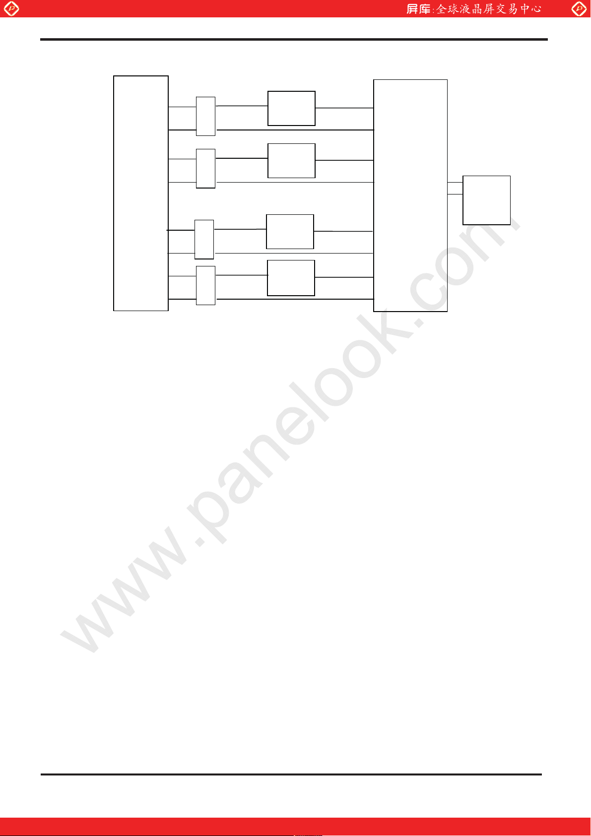
3) Lamp Current measurement method (The current meter is inserted in cold line)
LCD
Module
CTL
CTH
CTL
CTH
A
A
CTL
A
INVERTER
Power-
Supply
CTH
CTL
A
CTH
4) a. Frequency in this range can make the characteristics of electric and optics maintain in +/- 10%
except color coordinates.
b. Frequency in 50~60kHz can make characteristics of electric and optics better.
c. Frequency in 45~80kHz won’t damage the lifetime and reliability of lamp.
d. Lamp frequency of inverter may produce interference with horizontal(or vertical) synchronous
frequency,and this may cause horizontal beat on the display.Therefore, please adjust lamp
frequency, and keep inverter as far from module as possible or use electronic shielding
between inverter and module to avoid the interference.
5) Definition of the lamp life timeΚ
a. Luminance (L) under 50% of specification.
b. Starting Lamp Voltage: over130% of the initial value. Ta=25к
6) The condition of Turn-on and Turn-off operation is as below:
a. Lamp current is 7.5mA
b. Frequency is 10 sec.(on)/10 sec.(off)
c. Repeat it for 100 thousand times
d. The lamp hue variation must smaller than 0.03
e. It should not have motion fail when starting lamp voltage is lower than 130%of the initial
value.
7) For keeping good lighting situation, when design the inverter, it must be considered that the
voltage large than starting lamp voltage.
8) WL=IL x VL x 4Ζ(IL=7.5mAΔTa=25к)
9) The Starting Lamp Voltage (VS) of inverter must be driven large than one second.
10) The output voltage of inverter (Vn) must be the same phase of between any lamps.
11) The difference in voltage between any lamps ( V) must be smalleϦ r than 300V at the same time.
ExampleΚ VЮϦ ЮІ300VΔ VϦ Κ = V1(t)-V2(t)
CPT Confidential and Property
One step solution for LCD / PDP / OLED panel application: Datasheet, inventory and accessory!
ʳ
9/30
www.panelook.com
 Loading...