

CPT CLAA170EA07Q2 Specification
Chhuunngghh
C
waa
w
Piiccttuurree TTuubbeess,, LLttdd..
P
TTeecchhnniiccaall S
To :
BenQ
Sppeecciiffiiccaattiioonn
Date : 2005/11/07
CLAA170EA07Q2
ACCEPTED BY:
Tentative
APPROVED BY CHECKED BY PREPARED BY
Product Planning management General Division
Product Planning
Management General
Division
CHUNGHWA PICTURE TUBES, LTD.
1127 Hopin Rd., Padeh, Taoyuan, Taiwan 334, R.O.C.
TEL: +886-3-3675151 FAX: +886-3-377-3054
Doc.No: CLAA170EA07Q2-BenQ-tentative-2005/11/07 Issue Date: 2005/11/07
CPT CHUNGHWA PICTURES TUBES, LTD.,
1.OVERVIEW
CLAA170EA07Q2 is 17.0” color TFT-LCD (Thin Film Transistor Liquid Crystal Display)
module composed of LCD panel, driver ICs, control circuit and backlight.By applying 8 bit
digital data, 1280×1024, 16.2M-color images are displayed on the 17.0” diagonal screen.
Input power voltage is 5.0V for LCD driving.Inverter for backlight is not included in this
module. General specification are summarized in the following table:
ITEM SPECIFICATION
Display Area(mm) 337.920(H)x270.336(V) (17.0-inch diagonal)
Number of Pixels 1280(H)x1024(V)
Pixel Pitch(mm) 0.264(H)x0.264(V)
Color Pixel Arrangement RGB vertical stripe
Display Mode normally white, TN
Number of Colors 16.2M(6 Bit+FRC)
Brightness(cd/m^2) 300 cd/m2(Typ.)(Center point, Lamp current=7.5
mA)
Viewing Angle 140/130(Typ.)
Surface Treatment Anti-glare
Electrical Interface LVDS , 2Ch
Total Module Power(W) 22.3 (Typ.)
Optimum Viewing Angle 6 o’clock
Module Size(mm) 358.5(W)x296.5(H)x17.5(D)
Module Weight(g) 2000(typ)
Backlight Unit CCFL, 4 tables, edge-light(top*2/bottom*2)
2. ABSOLUTE MAXIMUM RATINGS
ITEM SYMBOL MIN. MAX. UNIT Remark
Power Supply Voltage for
LCD
Lamp Voltage VL 625 832 Vrms
Lamp Current IL 3 7.5 mArms Note4,7
Lamp Frequency FL 40 80 kHz
static electricity
Operation Temperature Top 0 50
Storage Temperature T
Delayed Discharge Time TD -- 1 Sec Note 8
CPT Confidential
VCC 0 6.5 V --
VESDt -200 200 V
VESD
C
-20 60
stg
1
/20
-8000 8000 V
℃
℃
CLAA170EA07Q2-tentative
Note 5
Note1,2,3,6
Note1,2,3
CPT CHUNGHWA PICTURES TUBES, LTD.,
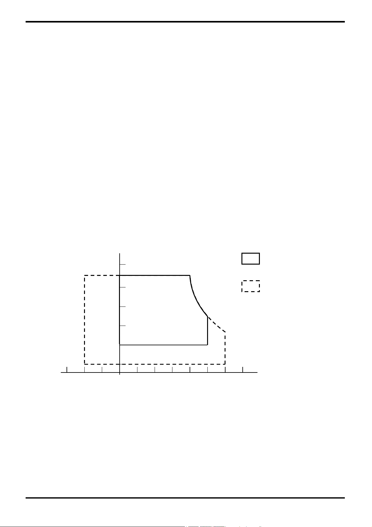
[Note 1] The relative temperature and humidity range are as below sketch, 90%RHMax.(Ta
≦40℃) .
[Note 2] The maximum wet bulb temperature ≦39℃(Ta>40℃) and without dewing.。
[Note 3] If you use the product in a environment which over the definition of temperature and
humidity too long to effect the result of eye-atching.。
[Note 4] The life time of the lamp is relate to the current of the lamp, so please accronding to
the description of the “(b) backlight” on page 6.
[Note 5] Test Condition: IEC 1000-4-2 ,
VESDt:Contact discharge to input connector;VESD
:Contact discharge to module
C
[Note 6] If you operate the product in normal temperature range, the center surface of panel
should be under 60℃.
[Note 7] When lamp current is out of the absolute maximum range,the life will fall rapidly
or shown unusual sign.
IL min 3mA only for test only, but we can’t guarantee the lifetime and performance
[Note 8] Delay lighting testing needs the volt above start volagte Vrms.Before the procedure
tube needs typical lighting for 1 minute and stay in the temperature 25±2℃ for 24
hours and then testing in the same condition in dark room .
90
80
60
(40,90)
Operating Range
Storage Range
(50,50.4)
-20
CPT Confidential
40
20
5
(60,27.7)
6040 50200
Temperature(°C)
2
/20
CLAA170EA07Q2-tentative

CPT CHUNGHWA PICTURES TUBES, LTD.,
3. ELECTRICAL CHARACTERISTICS
(a)TFT-LCD
Power Supply Voltage for LCD Vcc 4.5 5.0 5.5 V Note1
Power Supply Current for LCD Icc - 700 950 mA Note2
Permissive Input Ripple Voltage VRP - - 100 mVp-p Vcc=5.0V
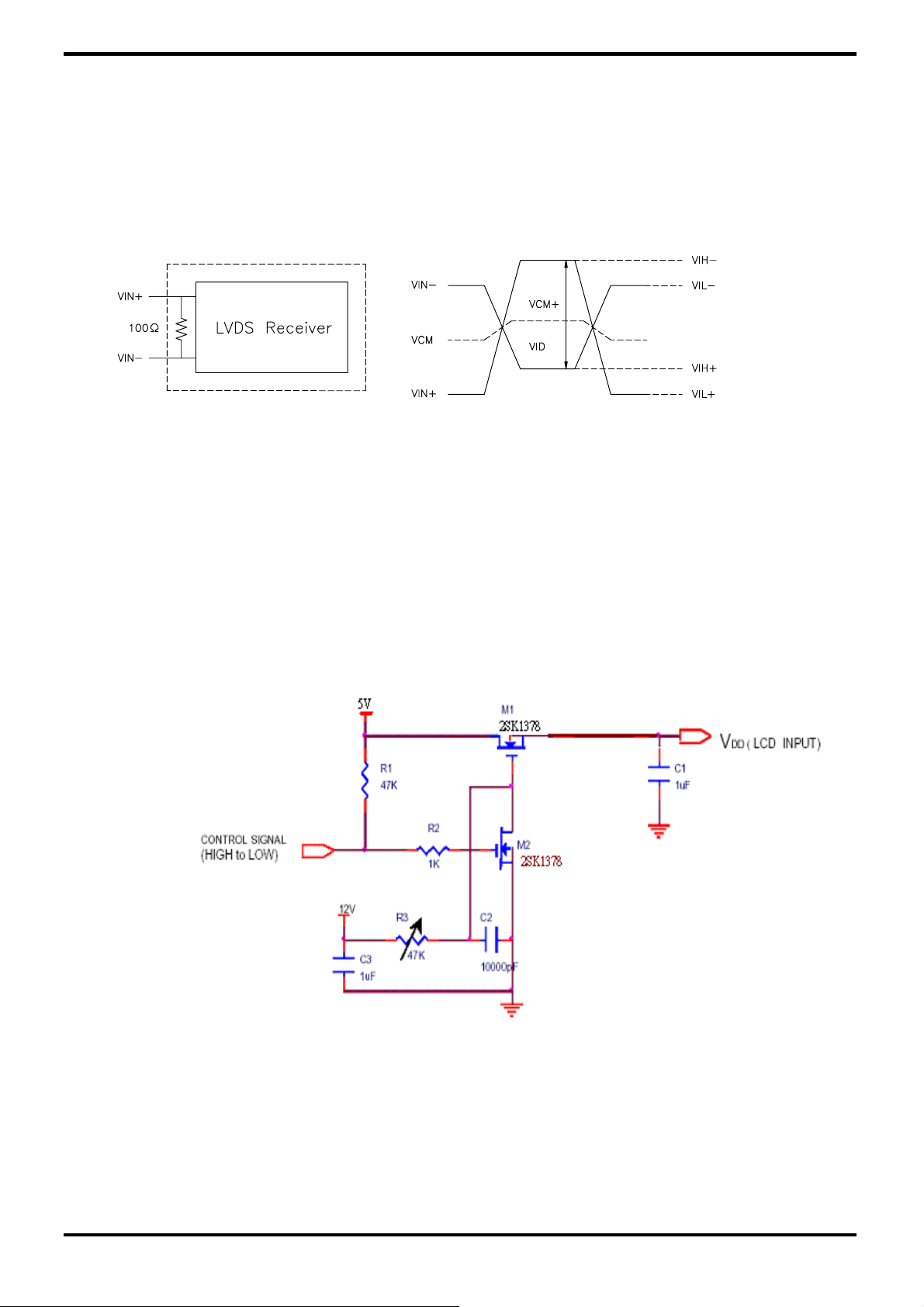
Differential impedance Zm 90 100 110 Ω
Logic input
Voltage
LVDS:IN+
,IN-
I rush Current Irush 3 A Note 4
Power consumption P 3.5 4.75 W Note2
Ta=25
ITEM SYMBOL MIN TYP MAX UNIT Remark
Common Mode Voltag VCM 1.125 1.25 1.375 V
Differential Input
Voltage
Threshold
Voltage(High)
Threshold
Voltage(Low)
|VID| 250 350 450 mV
VTH - - 100 mV
Note3
VTL -100 - - mV
[Note 1] VCC-turn-on conditions:
t1≦10ms 1 sec≦t4
0<t2≦20ms 200ms≦t5
0<t3≦50ms 200ms≦t6
4.5V
LCD Power Supply
Logic Signal
0.5V
Vin=5.0V
data
4.5V
0.5V
0.5V
℃
t2
t1
VL
Backlight Power Supply
t5 t6
Data: RGB DATA, DCLK, DENA
t3
t4
VCC-dip conditions
1)
When 3.6V≦Vcc(min)<4.5V: td≦10 ms
2)
When Vcc <3.6 V
VCC-dip conditions should also follow the VCC-turn-on conditions.
3.6
4.5V
CPT Confidential
3
/20
CLAA170EA07Q2-tentative
CPT CHUNGHWA PICTURES TUBES, LTD.,
[Note 2] Typical current situation :
64 gray scale level,1280 line mode, VCC=5.0V, Fh=64Khz,Fv=60Hz, Fclk=54 MHz .
[Note 3] LVDS Signal definition :
△VCM =|VCM
VID = VIN+ – VIN- ,
–VCM-|,
+
VIN+ = Positive differential DATA & CLK Input
VIN- = Negative differential DATA & CLK Input
△VID =|VID+–VID-|,
VID+ =|VIH+–VIH-|,
VID- =|VIL+–VIL-|,
VCM =(VIN+ +VIN-)/2,
VCM+ =(VIH
VCM- =(VIL
+VIH-)/2,
+
+VIL-)/2,
+
[Note4 ] Irush Measurement Condition
CPT Confidential
4
/20
CLAA170EA07Q2-tentative
CPT CHUNGHWA PICTURES TUBES, LTD.,
(b)Backlight
1.Electrical specification
ITEM SYMBOL MIN TYP MAX UNIT REMARK
Lamp Voltage VL
Lamp Current IL 3 7.5 8 mArms Note1
Interter Frequency FL 45 50 65 kHz Note2
Starting Lamp
Voltage
Ta=25
Vrms IL=7.0mA Note 1
Vrms
Vrms
Tb=0℃
Ta=25℃
VS
606 673.3 740.6
-- -- 1710
-- -- 1490
2. Life time
Lamp life Time Min. 40,000 Min. 40,000 Min. 30,000 hr
IL at 3.0 mA IL at 7.5 mA IL at 8 mA UNIT REMARK
Continuous Operation,
Rated time
(turn on/off)
-- Min.100,000 -- time Note 4
Note 3
[Note ] Measuring inverter Type:M063-4
If the waveform of light up-driving is asymmetric, the distribution of mercury inside
the lamp tube will become unequally or will deplete the Ar gas in it. Then it may
cause the abnormal phenomenon of lighting-up. Therefore, designers have to try
their best to forfill the conditions under the inverter designing-stage as below:
•The degrees of unbalance: <10%
•The ratio of wave height:<√2 ±10%
℃
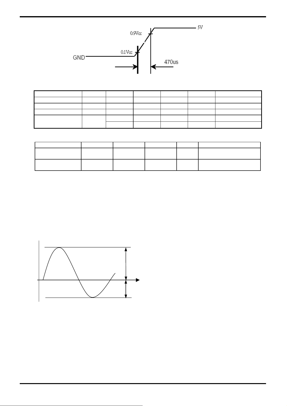
A:The degrees of unbalance =︱Ip – I-p︱/ Irms ×100 (%)
B:The ratio of wave height = Ip (or I-p) / Irms
CPT Confidential
5
/20
Ip
I-p
Ip:high side peak
I-p:low side peak
CLAA170EA07Q2-tentative
CPT CHUNGHWA PICTURES TUBES, LTD.,
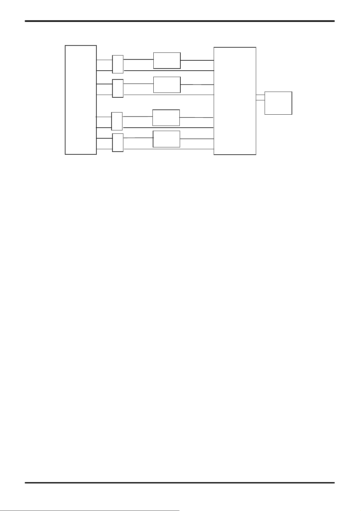
[Note 1] Lamp Current measurement method ( The current meter is inserted in cold line)
LCD
Module
CTL
CTH
CTL
CTH
CTL
A
A
A
INVERTER
PowerSupply
CTH
CTL
CTH
A
[Note 2]
1.Frequency in this range can mala the characterisitics of electric and optics
maintain in +/- 10% except hue.
2.If the lamp frequency can be maintain in 50~60KHz, the better charactristics of
the electrical and the optical can be presented.
3.If the operating frequency is 40~80 KHz, the life time and the reliability of the lamp
will not be affect.
4.Lamp frequency of inverter may produce interference with horizontal synchronous
frequency,and this may cause horizontal beat on the display.Therefore, please
adjust lamp frequency, and keep inverter as far from module as possible or use
electronic shielding between inverter and module to avoid the interference.
[Note 3] Definition of the lamp life time: Luminance (L) under 50% of specification
starting lamp voltage or starting lamp voltage is more than 130% of the initial
value
[Note 4] The condition of Turn-on and Turn-off operation is as below:
a. Lamp current is 7.0mA
b. Frequency is 10 sec.(on)/10 sec.(off)
c. Repeat it for 10 thousand times
d. The result of eye-atching of the lamp hue is normal, and can switch the lamp.
It should not have motion fail when starting lamp voltage is lower than 130% of
the initial value
[Note 5] It is necessary to consider the maximal value when design inverter,in order to
asure lighting.
[Note 6] WL=IL x VL x 4。(IL=7mA,Ta=25
℃)
CPT Confidential
6
/20
CLAA170EA07Q2-tentative
 Loading...