

CPT CLAA150XP01 Specification

f
C
hhuunngghhw
C
Teecchhnniiccaall SSppeecciiffiiccaattiioonn
T
waa PPiiccttuurree
Tuubbeess,,
T
Lttdd..
L
To :
Date : 2005/07/11
CPT TFT-LCD
CLAA150XP01
ACCEPTED BY:
APPROVED BY CHECKED BY PREPARED BY
TFT-LCD Product
Planning Management
General Division
CHUNGHWA PICTUER TUBES, LTD.
1127 Hopin Rd., Padeh, Taoyuan, Taiwan 334, R.O.C.
TEL: +886-3-3675151 FAX: +886-3-377-3001
Doc.No: CLAA150XP01-DELL-Ver.1-2005/07/11 Issue Date: 2005/07/11
T- 3650002- 000- A

CPT CHUNGHWA PICTURES TUBES, LTD.,
RECORD OF REVISIONS
Revision No. Date Page Description
Ver.1 2004/03/26 -- Formal specification for 150XP01 was first issued.
CPT Confidential
1
/24
CLAA150XP01-DELL-Ver1-20040711

CPT CHUNGHWA PICTURES TUBES, LTD.,
CONTENTS
No Item Page
1 OVERVIEW 3
2 ABSOLUTE MAXIMUM RATINGS 4
3 ELECTRICAL CHARACTERISTICS 5
4 INTERFACE PIN CONNECTION 9
5 INTERFACE TIMING 10
6 DATA MAPPING 12
7 COLOR DATA ASSIGNMENT 13
8 BLOCK DIAGRAM 14
9 MECHANICAL SPECIFICATION 15
10 OPTICAL CHARACTERISTICS 17
11 RELIABILITY TEST CONDITIONS 22
12 HANDLING PRECAUTIONS FOR TFT-LCD MODULE 23
CPT Confidential
2
/24
CLAA150XP01-DELL-Ver1-20040711

CPT CHUNGHWA PICTURES TUBES, LTD.,
1. OVERVIEW
CLAA150XP01 is 15” color TFT-LCD (Thin Film Transistor Liquid Crystal Display) module
composed of LCD panel, LVDS driver ICs, control circuit and backlight. By applying 8 bit digital data,
1024×768, 162M-color images are displayed on the 15” diagonal screen. Interface of data and control
signals is Typ. 65 MHz digital. Inverter for backlight is not included in this module. General
specification are summarized in the following table:
ITEM SPECIFICATION
Display Area (mm) 304.1(H)x228.1(V) (15.0-inch diagonal)
Number of Pixels
Pixel Pitch (mm)
Color Pixel Arrangement RGB vertical stripe
Display Mode Normally white, TN
Number of Colors 16.2M(6bits+FRC)
Brightness (cd/m^2) 250cd/m2 (Typ.)(center, 8.0mA)
Viewing Angle 120/105(Typ.)
Wide Viewing Angle Technology Optical Compensation Film
Surface Treatment Anti-glare
Response Time 16ms
Color Saturation 65%
Total Module Power (W) 10.4+2.1(Typ.)
Optimum Viewing Angle 6 o’clock
Module Size (mm)
326.5(W) × 253.5(H) × 11.0(D) (Typ.)
Module Weight (g) 1060(Typ.)
Backlight Unit CCFL, 2 tables, edge-light (top/bottom)
The LCD Products listed on this document are not suitable for use of aerospace equipment, submarine
cables, and nuclear reactor control system and life support systems. If customers intend to use these
LCD products for above application or not listed in "Standard" as follows, please contact our sales
people in advance.
Standard: Computer, Office equipment, Communication equipment, Test and Measurement equipment,
Machine tool, Industrial robot, Audio and Visual equipment, Other consumer products.
1024 (H) × 768(V)
0.297(H) × 0.297(V)
CPT Confidential
3
/24
CLAA150XP01-DELL-Ver1-20040711
CPT CHUNGHWA PICTURES TUBES, LTD.,
2. ABSOLUTE MAXIMUM RATINGS
The following are maximun values which, if exceeded, may cause faulty operation or damage to the
unit.
ITEM SYMBOL MIN. MAX. UNIT Remark
Power Supply Voltage For LCD VDDD - 4.0 V
IDDD Rush Current IRUSHd - 4.0 A *1)
Lamp Voltage
Lamp Current
Lamp Frequency
Operation Temperature (Surrounding) *1)
Storage Temperature *1)
[Note]
*1) In 100 µsec ,but in the situation of longer VDD rising time, the RUSH value will get smaller.
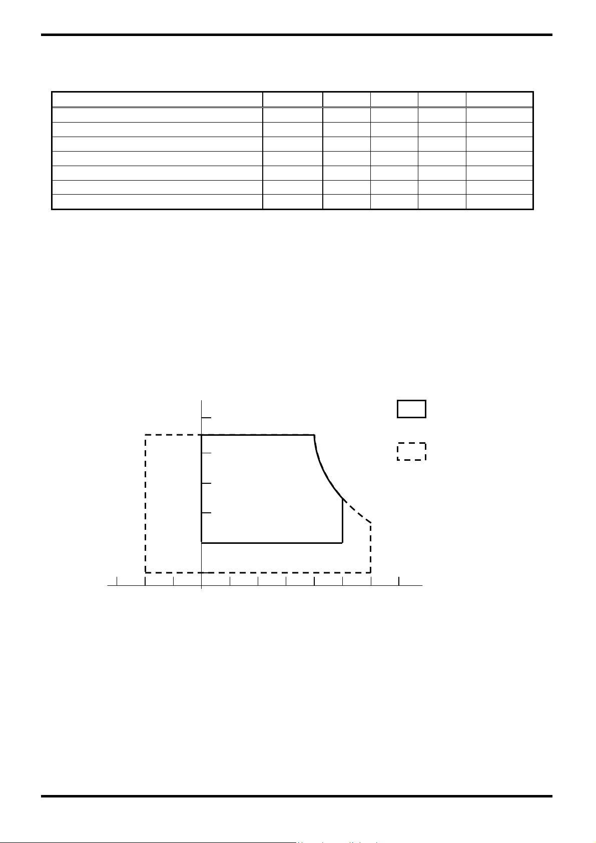
*2) The relative temperature and humidity range are as below sketch, 90%RHMax. (Ta≦40℃)
*3) The maximum wet bulb temperature ≦39℃(Ta>40℃) and without dewing.
*4) If you use the product in a environment which over the definition of temperature and humidity
too long to effect the result of eye-atching.
*5) If you operate the product in normal temperature range, the center surface of panel should be
under 60℃.
Humidity:
Humidity≦85%RH without condensation.
Relative Humidity ≦90% (Ta≦ 40℃)
Wet Bulb Temperature ≦39℃(Ta≧40℃)
Relative humidity(%RH)
90
80
60
40
20
5
-20
Temperature(°C)
VL 522 700 Vrms
IL 3 8.5 mArms
FL 40 80 kHz
Top
0 50 ℃ *2), 3), 4), 5)
Tstg -20 60 ℃ *2), 3), 4)
(40,90)
Operating Range
Storage Range
(50,50.4)
(60,27.7)
40 50 60200
CPT Confidential
4
/24
CLAA150XP01-DELL-Ver1-20040711

CPT CHUNGHWA PICTURES TUBES, LTD.,
3. ELECTRICAL CHARACTERISTICS
3.1 TFT-LCD Ta=25℃
ITEM SYMBOL MIN TYP MAX UNIT REMARK
Power Supply Voltage for Logic
Power Supply Current for Logic
Permissive Ripple Voltage for
Logic
Differential impendence Zm 90 100 110 Ω *3)
[Note]
*1)Power、data sequence
t1≦10ms 1 sec≦t4
0<t2≦50ms 200ms≦t5
0<t3≦50ms 200ms≦t6
LCD Power Supply
Logic Signal
2.97V
0.33V
t1
Backlight Power Supply
VCC-dip state:
1) When 2.4 V≦VCC<3.0V, td≦10 ms.
2) VCC-dip condition should also follow the VCC-turn-off condition.
VDDD 3.0 3.3 3.6 V *1)
IDDD -- 600 700 mA *2)
VRPd -- -- 100 mVp-p Vin=+3.3V
Vin=3.3V
2.97V
data
t2
VL
t5
Data: RGB DATA, DCLK, DENA
2.4V
td
t3
t6
0.33
t4
Vcc
3.0V
0.33V
CPT Confidential
5
/24
CLAA150XP01-DELL-Ver1-20040711

CPT CHUNGHWA PICTURES TUBES, LTD.,
*2) Typical current situation: 0~255-gray-bar pattern, 768 line mode, VCC=+3.3V, f
=65 MHz.
CLK
*3) Definition of the LVDS data
VIN+:Positive differential DATA & CLK input
VIN- :Negative differential DATA & CLK input
VID = VIN
△VCM =|VIN
△VID =|VIN
–
+
VIN-
–
VCM-|
+
–VID-|
+
VID+ =|VIN+–VIH-|
VID- =|VIN+–VIL-|
VCM =(VIN+ +VIN-)/2
VCM+ =(VIN
VCM- =(VIN
+VIH-)/2
+
+VIL-)/2
+
CPT Confidential
6
/24
CLAA150XP01-DELL-Ver1-20040711
CPT CHUNGHWA PICTURES TUBES, LTD.,
3.2 Backlight
(a) Electrical Characteristics Ta=25℃
ITEM SYMBOL MIN TYP MAX UNIT REMARK
Lamp Voltage VL 522 580 638 Vrms IL=8.0mA
Lamp Current IL 6 8.0 8.5 mArms *1)
Inverter Frequency FI 40 50 60 kHz *2)
Starting Lamp
Voltage
VS
1280 -- -- Vrms
985 -- -- Vrms
Ta=0℃
Ta=25℃
(b) Lamp Life Time
ITEM IL @3.0 mA IL @8.0 mA IL @8.5 mA UNIT REMARK
Lamp Life Time Min. 50,000 Min. 30,000 Min. 20,000 hr
Turn-on and Turn-off
Operation
-- Min. 100,000 -- time
Continuous
Operation*3)
Continuous
Operation*4)
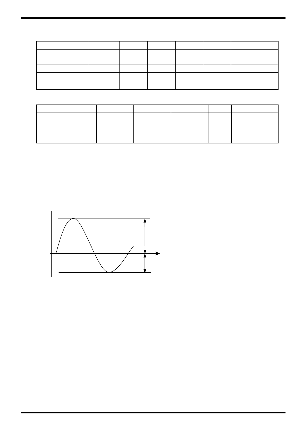
[Note] If the waveform of light up-driving is asymmetric, the distribution of mercury inside the
lamp tube will become unequally or will deplete the Ar gas in it. Then it may cause the
abnormal phenomenon of lighting-up. Therefore, designers have to try their best to forfill the
conditions under the inverter designing-stage as below:
•The degrees of unbalance: <10%
•The ratio of wave height:<√2 ±10%
Ip
I-p
A:The degrees of unbalance =︱Ip – I-p︱/ Irms ×100 (%)
B:The ratio of wave height = Ip (or I-p) / Irms
Ip:high side peak
I-p:low side peak
CPT Confidential
7
/24
CLAA150XP01-DELL-Ver1-20040711
 Loading...