

Page 1
Installation, Operation &
Maintenance Manual
For
Series CST
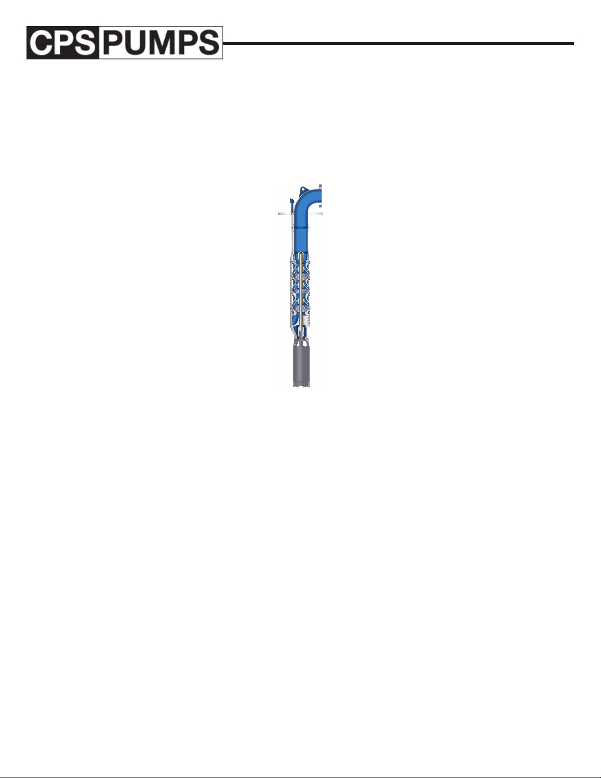
Submersible Turbine Pumps
IOM-0000-CST
IOM-0000-CST
Copyright © 2018 CPS-Pumps
www.cps-pumps.com
IOM Manual: IOM-0000-CST
Series CST: Submersible Turbine
01/01/2018 - Edition 1A
Page 2

Table of Contents
4 ...............INTRODUCTION
4 ...............SAFETY CONSIDERATIONS
5 ...............PUMP IDENTIFICATION
5 ...............MANUFACTURER
...............TYPE OF PUMP
5
5
...............DATE OF MANUFACTURE
5 ...............INSTALLATION, OPERATION & MAINTENANCE MANUAL IDENTIFICATION
6 ...............GENERAL INSTRUCTIONS
6 ...............HANDLING AND TRANSPORT
...............METHOD OF TRANSPORT
6
6
...............STORAGE
7 ...............INSTALLATION & ALIGNMENT
7 ...............PREPARATION
8 ...............RECEIVING THE PUMP
8 ...............ELECTRICAL
CONSIDERATIONS
9 ...............PROVIDING A PROPER POWER SUPPLY
9 ...............SELECTING AND INSTALLING A PROPER MOTOR CONTROL SYSTEM
9 ...............SELECTING THE PROPER DROP CABLE
9 ...............MAKING THE SPLICE BETWEEN THE MOTOR LEADS AND THE DROP
CABLE
9 ...............PROPERLY GROUNDING THE UNIT
9 ...............SELECTING AND INSTALLING AUXILIARY EQUIPMENT
10 ...............PRE-INSTALLATION MOTOR AND DROP CABLE CHECKS AND
PREPARATION
10 ...............MOTOR SERVICING
10 ...............ATTACHING THE MOTOR TO THE PUMP
10 ...............TESTING BEFORE SPLICING DROP CABLE TO MOTOR LEADS
10 ...............MOTOR TESTS
10 ...............DROP CABLE TESTS
10 ...............SPLICING DROP CABLE TO MOTOR LEADS
10 ...............TESTING AFTER SPLICING DROP CABLE TO MOTOR LEADS
11 ............... INSTALLING THE PUMP
13 ...............ROUTINE OPERATION AND MAINTENANCE
...............ROUTINE INSPECTIONS
13
13
...............ROUTINE TESTING
14 ...............PERFORMANCE TESTING
18 ...............ELECTRICAL TESTS
18 ...............MEASURING INSULATION RESISTANCE (GROUND TEST)
...............MEASURING RESISTANCE BETWEEN LEADS (MOTOR WINDING RESIS-
20
TANCE)
22
...............ASSEMBLY OF PUMP AND
MOTOR
23 ...............UPTHRUST ADJUSTMENT
www.cps-pumps.com
2
IOM Manual: IOM-0000-CST
Series CST: Submersible Turbine
01/01/2018 - Edition 1A
Page 3

23 ...............PUMPS WITH 4” AND 6” MOTORS
24 ...............PUMPS WITH 8” MOTORS
24 ...............PUMPS WITH 6”, 8”, 10”, 12”, 14” AND 16” MOTORS (OPEN BEARING STYLE)
24 ...............RECOMMENDED SPARE PARTS
26 ...............SUBMERSIBLE TURBINE BOWL ASSEMBLY
IOM Manual: IOM-0000-CST IOM
Series CST: Submersible Turbine
01/01/2018 - Edition 1A
3
www.cps-pumps.com
Page 4
INTRODUCTION
Maximum Lifting Speed: 15 feet/second.
e pumps covered in this manual, when installed correctly, will
last for many years in service. In order to gain the most from
this equipment, this manual should be read thoroughly and followed during all stages of installation and operation.
SAFETY CONSIDERATIONS
e CPS-Pumps CST submersible turbine pumps have been
designed and manufactured for safe operation. In order to ensure safe operation, it is very important that this manual be read
in its entirety prior to installing or operating the system. CPSPumps shall not be liable for physical injury, damage or delays
caused by a failure to observe the instructions for installation,
operation and maintenance contained in this manual.
Remember that every pump has the potential to be dangerous
because of the following factors:
• Parts are rotating at high speeds
• High pressures may be present
• High temperatures may be present
• Highly corrosive and/or toxic chemicals may be present
Paying constant attention to safety is always extremely important. However, there are often situations that require special
attention. ese situations are indicated throughout this book
by the following symbols:
If in a climate where the uid in the system could freeze, never
leave liquid in the pump. Drain the system completely. During winter months and cold weather, the liquid could freeze and
damage the system components. Always remember to drain the
casing assemblies complete.
Do not run the equipment dry or start the pump without the
proper prime (ooded system). Signicant damage can occur to
the unit if even run for a short time period without a fully lled
casing assembly.
Never operate the pump(s) for more than a short interval with
the discharge valve closed. e length of the interval depends
on several factors including the nature of the uid pumped and
it’s temperature. Contact CPS-Pumps Engineering for additional support if required.
Excessive pump noise or vibration may indicate a dangerous operating condition. e pump(s) must be shutdown immediately.
Do not operate the pump and/or the system for an extended
period of time below the recommended minimum ow.
It is absolutely essential that the rotation of the motor be
checked before starting any pump in the system. Incorrect
rotation of the pump for even a short period of time can cause
severe damage to the pumping assembly.
DANGER - Immediate hazards which WILL result in severe
personal injury or death.
WARNING – Hazards or unsafe practices which COULD result
in severe personal injury or death.
CAUTION – Hazards or unsafe practices which COULD result
in minor personal injury or product or property damage.
If the liquid is hazardous, take all necessary precautions to avoid
damage and injury before emptying the pump casing.
Residual liquid may be found in the pump casing, suction and
discharge manifolds. Take the necessary precautions if the liquid is hazardous, ammable, corrosive, poisonous, infected, etc.
Always lockout power to the driver before performing pump
maintenance.
Never operate the pump without the coupling guard (if supplied) and all other safety devices correctly installed.
Do not apply heat to disassemble the pump or to remove the
impeller. Entrapped liquid could cause an explosion.
If any external leaks are found while pumping hazardous product, immediately stop operations and repair.
www.cps-pumps.com
4
IOM Manual: IOM-0000-CST
Series CST: Submersible Turbine
01/01/2018 - Edition 1A
Page 5
PUMP IDENTIFICATION
MANUFACTURER
CPS-Pumps
125 Morrison Drive
Rossville, TN 38066
United States of America
TYPE OF PUMP
e CPS-Pumps CST submersible turbine pump is a vertical
turbine, multi stage, Francis impeller design centrifugal pump.
STAGES : Number of stages within
pump
GPM : Rated capacity of pump
TDH : Rated Total Dynamic
Head of pump
RPM : Speed of pump
HP : HP of pump
IMPELLER : Impeller model of pump
DISCHARGE (IN) : Discharge size of pump in
inches
SUCTION (IN) : Suction size of pump in
inches
WARRANTY
DATE OF MANUFACTURE
e date of manufacture is indicated on the pump data plate.
INSTALLATION, OPERATION &
MAINTENANCE MANUAL IDENTIFICATION
Prepared: January 01, 2018 Edition: 01
Revision: Date of Revision:
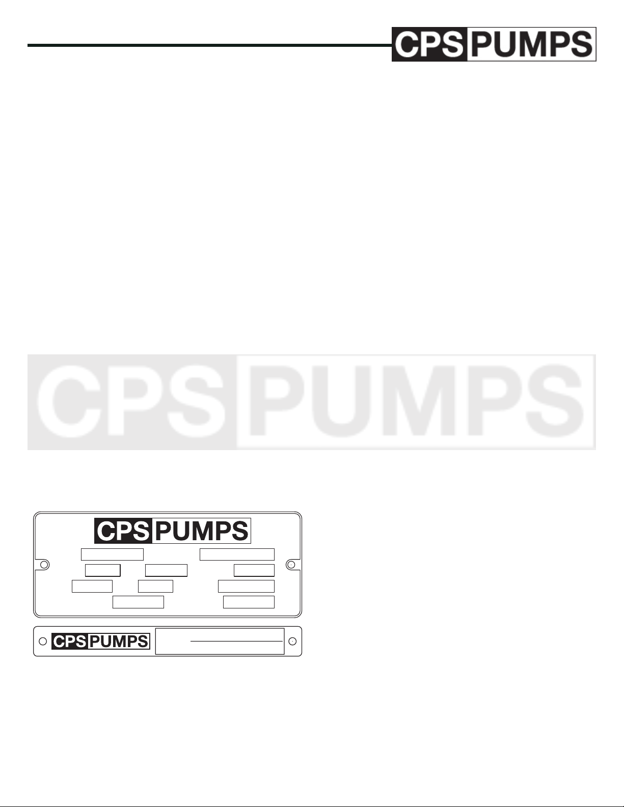
All pumps are identied by serial number, model number and
size. is information is stamped on a stainless steel identication plate which is permanently attached to the pump. Do not
remove this plate as it will be impossible to identify the pump
without it. Refer to the pump information in this manual for
specic information.
NAMEPLATE INFORMATION
SERIAL NOMODEL
STAGES GPM TDH
RPM HP
DISCHARGE (IN) SUCTION (IN)
FIGURE 1 – Pump Data Plate (Discharge Head & Bell Tag)
MODEL : Model designation of
pump (8CKC-4)
SERIAL NUMBER : Serial Number of pump
unit (issued by Production
Control)
IOM Manual: IOM-0000-CST IOM
Series CST: Submersible Turbine
01/01/2018 - Edition 1A
IMPELLER
SERIAL #
MODEL #
CPS-Pumps guarantees that only high quality materials are
used in the construction of our pumps and that machining and
assembly are carried out to the highest standards.
e pumps are guaranteed against defective materials and/or
faulty craftsmanship for a period of twelve (12) months from
the date of startup or eighteen (18) months from shipment
whichever occurs rst.
Replacement of parts or of the pump itself can only be carried
out after careful examination of the pump by qualied personnel.
e warranty is not valid if third parties have tampered with the
pump. If the warranty security seal (which is uniquely barcoded) has been removed without PRIOR consent, warranty
consideration may be denied by CPS-Pumps.
is warranty does not cover parts subject to deterioration or
wear and tear (mechanical seals, pressure and vacuum gauges,
rubber or plastic items, bearings, etc.) or damage caused by
misuse or improper handling of the pump by the end user.
Parts replaced under warranty become the property of CPSPumps.
Contact the CPS-Pumps’ factory:
CPS-Pumps
125 Morrison Drive
Rossville, TN 38066
United States Of America
5
www.cps-pumps.com
Page 6

GENERAL INSTRUCTIONS
e pump and motor unit must be examined upon arrival to
ascertain any damage caused during shipment. If damaged
immediately notify the carrier and/or the sender. Check that
the goods correspond exactly to the description on the shipping
documents and report any dierences as soon as possible to the
sender. Always quote the pump type and serial number stamped
on the data plate.
e pumps must be used only for applications for which the
manufacturers have specied:
• e construction materials
• e operating conditions (ow, pressure, temperature, etc.)
• e eld of application
In case of doubt, contact CPS-Pumps.
ponents for which they have been supplied.
Maximum lifting speed: 15 feet/second
It is important to exercise extreme care in handling and installing all parts. Certain items are precision machined for proper
alignment and, if dropped, banged, sprung or mistreated in any
way, misalignment and malfunction will result. Other components, such as the electrical cable, may be vulnerable to gouging or scung. Parts which are too heavy to be lifted from the
transporting car or truck should be skidded slowly and carefully
to the ground to prevent damage. Never unload by dropping
parts directly from the carrier to the ground and never use shipping crates for skids.
Upon receipt of the pump, a visual check should be made to
determine if any damage has been incurred during transit or
shipment. e main areas to diligently inspect are:
• Broken or cracked bowl assembly, including the
motor bracket, motor, discharge head and discharge
anges
• Bent or damaged shafts
• Broken motor end bells, bent lifting eye bolts or
damaged conduit boxes on the driver
• Missing parts
Parts and/or accessories are sometimes wrapped individually
or fastened to the equipment. Coupling hubs are shipped in
separate boxes (sometimes housed under the coupling guard). If
any damage or loss has been incurred, promptly contact CPSPumps and the freight company that delivered the equipment.
HANDLING AND TRANSPORT
METHOD OF TRANSPORT
e pump must be transported in the horizontal position
INSTALLATION
During installation and maintenance, all components must
be handled and transported securely by using suitable slings.
Handling must be carried out by specialized personnel to avoid
damage to the pump and persons. e lifting rings attached to
various components should be used exclusively to lift the com-
If the bowl assembly is strapped to an I-beam for support, do
not remove the bowl assembly from the I-beam support until
the bowl assembly is in the vertical orientation.
If job site conditions permit, you may be able to install directly
from the truck that delivered the pump. If not, move the components to the installation area and lay them out in a clean and
protected space convenient to the work location. Column pipe
sections should be placed on suitable timbers to keep them out
of the dirt, arranged so that the coupling ends point toward the
wellhead. e bowl/motor assembly should be left on the skids
until lifted for installation. e power cable and motor leads
must receive special protection to avoid damage to the jacket or
insulation.
If installation cannot begin within a few days after delivery,
segregate and identify all components of the shipment so they
won’t be confused with other equipment arriving to the job site.
READ and FOLLOW the storage instructions carefully
because care of the pump during this period before installation
can be as important as maintenance after operation has begun.
Check all parts against the packing list to make sure nothing
is missing. It is much better to nd out now than during the
installation. Report any discrepancies immediately to CPSPumps.
STORAGE
SHORT-TERM STORAGE
www.cps-pumps.com
Normal packaging is designed to protect the pump during shipment and for dry, indoor storage for up to two months or less.
If the pump is not to be installed or operated soon after deliv-
6
IOM Manual: IOM-0000-CST
Series CST: Submersible Turbine
01/01/2018 - Edition 1A
Page 7

ery, store the unit in a clean, dry place, having slow changes in
environmental conditions. Steps should be taken to protect the
pump against moisture, dirt and foreign particulate intrusion.
e procedure followed for this short-term storage is summarized below:
Standard Protection for Shipment :
a. Loose unmounted items, including, but not limited
to, oilers, packing, coupling spacers, stilts and mechanical seals are packaged in a water proof plastic bag and
placed under the coupling guard.
b. Inner surfaces of the bearing housing, shaft (area
through bearing housing) and bearings are coated with
Cortec VCI-329 rust inhibitor or equal.
c. Regreasable bearings are packed with grease (Exxon
Mobile Polyrex EM).
d. After a performance test, if required, the pump is
checked for drainage (some residual water may remain in the bowl assembly). en, internal surfaces of
ferrous casings, covers, ange faces and the impeller
surface are sprayed with Calgon Vestal Labs RP-743m,
or equal. Exposed shafts are taped with Polywrap.
e. Flange faces are protected with plastic covers secured with plastic drive bolts. 3/16 in (7.8 mm) steel or
1/4 in (6.3 mm) wood covers with rubber gaskets, steel
bolts and nuts are available at extra cost.
LONG-TERM STORAGE
Long-term storage is dened as more than two months, but less
than 12 months. e procedure CPS-Pumps follows for longterm storage of pumps is given below. ese procedures are in
addition to the short-term procedure above.
Solid wood skids are utilized. Holes are drilled in the skid to
accommodate the anchor bolt holes in the base plate, or the casing and bearing housing feet holes on assemblies less base plate.
Tackwrap sheeting is then placed on top of the skid and the
pump assembly is placed on top of the Tackwrap. Metal bolts
with washers and rubber bushings are inserted through the skid,
the Tackwrap and the assembly from the bottom of the skid and
are then secured with hex nuts. When the nuts are “snugged”
down to the top of the base plate or casing and bearing housing feet, the rubber bushing is expanded, sealing the hole from
the atmosphere. Desiccant bags are placed on the Tackwrap.
e Tackwrap is drawn up around the assembly and hermetically (heat) sealed across the top. e assembly is completely
sealed from the atmosphere and the desiccant will absorb any
entrapped moisture. A solid wood box is then used to cover the
assembly to provide protection from the elements and handling.
is packaging will provide protection up to twelve months
without damage to mechanical seals, bearings, lip seals, etc. due
to humidity, salt laden air, dust, etc. After unpacking, protection will be the responsibility of the user. Addition of oil to the
bearing housing will remove the inhibitor. If units are to be idle
for extended periods after addition of lubricants, inhibitor oils
and greases should be used.
f. All assemblies are bolted to a wood skid which connes the assembly within the perimeter of the skid.
g. Assemblies with special paint are protected with a
plastic wrap.
h. All assemblies having external piping (seal ush and
cooling water plans), etc. are packaged and braced to
withstand normal handling during shipment. In some
cases components may be disassembled for shipment.
e pump must be stored in a covered, dry location.
It is recommended that the following procedure is taken:
1. Ensure that the suction and discharge anges are
covered and secured with cardboard, plastic or wood to
prevent foreign objects from entering the pump.
2. If the pump is to be stored outdoors with no
overhead covering, cover the unit with a tarp or other
suitable covering.
IOM Manual: IOM-0000-CST IOM
Series CST: Submersible Turbine
01/01/2018 - Edition 1A
Every three months, the shaft should be rotated approximately
10 revolutions.
INSTALLATION & ALIGNMENT
PREPARATION
Before installing the pump, clean the discharge ange thoroughly. Remove any protective coatings that may be on the
shaft.
If the pump is coming from Short-Term or Long-Term storage
and has been prepared for storage in the manner above, remove
all grease and/or oil from the bearings. e bearings should be
ushed with an appropriate uid to remove any contamination
prior to placing the pump into service.
7
www.cps-pumps.com
Page 8
TERMINAL BOX
SUBMERSIBLE MOTOR
ELECTRICAL
PANEL
DISCHARGE ELBOW
DROP CABLE
CABLE CLAMP
CABLE SPLICE
MOTOR LEADS
MOTOR LEADS
SHIELD
DISCHARGE TO
ABOVE GROUND
PIPING SYSTEM
WELL CASING
COLUMN PIPE
COUPLING
WATER LEVEL
COLUMN PIPE
CHECK VALV E
PUMP
PUMP SUCTION
e height of the equipment must be sucient to accommodate the
longest component to be installed.
Equipment for removal of the pump after it has been in operation
must be capable of lifting the above weight plus the weight of the
water in the column pipe (if applicable).
RECEIVING THE PUMP
Immediately upon receipt, check that the number of boxes and
pieces received is the same as shown on the freight bills. Check
for shipping damage. Note any shortages or damages on the
carrier’s copy of the freight bill prior to signing. Report these
damages or shortages to CPS-Pumps or your local factory representative immediately.
If facilities are not available for lifting the materials o the carrier’s vehicle, use skids for unloading rather than allowing the
parts to drop to the ground. Even though a pump is made up
of heavy steel parts, it is a piece of machinery and it is essential
that its parts be handled with care. It is extremely easy to damage shafting, threaded parts, and mating surfaces of parts which
must t together. Even a minor bend in one piece of shafting
can cause a pump to vibrate excessively; thus shortening the life
of the pump drastically.
ELECTRICAL
CONSIDERATIONS
A major portion of the work associated with a submersible
pump is the electrical consideration. It is not the intent of this
manual to provide detailed instructions for the electrical work.
e services of a competent power electrician or electrical contractor will be required. All work must be done in accordance
with applicable codes, the pump motor manual, instructions
for other equipment that is part of the installation and sound
electrical practices. e electrical work performed will include
but not be limited to the following:
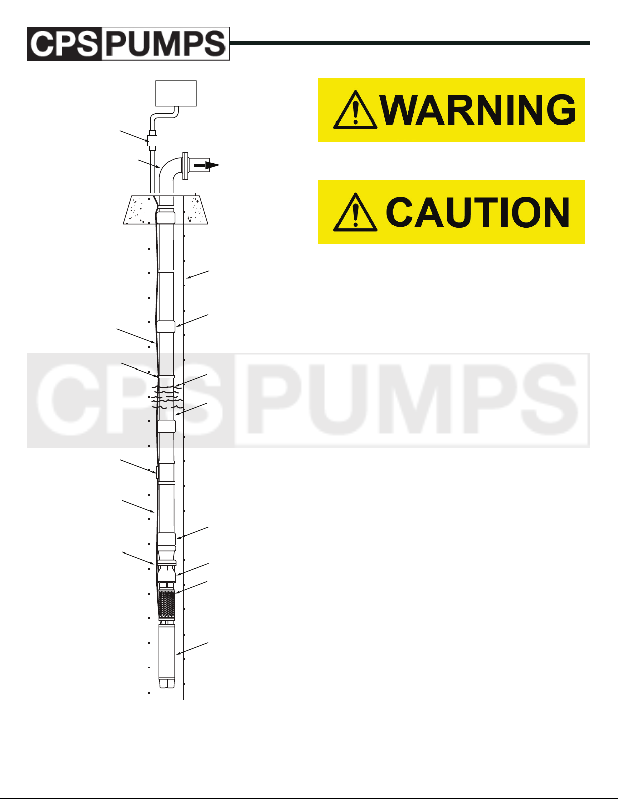
FIGURE 2 – Submersible Turbine Installation
www.cps-pumps.com
8
IOM Manual: IOM-0000-CST
Series CST: Submersible Turbine
01/01/2018 - Edition 1A
Page 9

PROVIDING A PROPER POWER
SUPPLY
e power supply must have an adequate capacity (KVA) and
must be of the proper voltage, phase and frequency to match
the motor requirements. ree phase systems should have a full
three phase supply utilizing three individual transformers or one
three phase transformer. Open delta or wye systems using only
two transformers must be de-rated. Such installations are also
more likely to suer from phase unbalance problems. Unbalanced voltage on three phase power sources will cause unbalanced motor currents. Motor current unbalances in excess of
5% can be expected to cause excessive heating in the motor, resulting in poor motor performance, nuisance overload tripping,
and premature failure of the motor. If the power company cannot guarantee less than 5 percent unbalance, the use of the next
larger size motor and the next larger size cable is recommended.
Contact CPS-Pumps for further information. e warranty can
be voided by the use of an improper power supply.
MAKING THE SPLICE BETWEEN
THE MOTOR LEADS AND THE
DROP CABLE
A water-tight splice must be made to connect the drop cable to
the motor leads. See PRE-INSTALLATION MOTOR AND
DROP CABLE CHECKS AND PREPARATION on page
10.
PROPERLY GROUNDING THE
UNIT
All units must be grounded in accordance with applicable codes.
SELECTING AND INSTALLING A
PROPER MOTOR CONTROL SYSTEM
e motor control system must be sized to accommodate the
pump motor. e control system should protect the motor
from damage from abnormal conditions such as low voltage,
high voltage, overload, excessive current unbalance, phase loss,
overheating, lightening, etc. Single phase 3-wire motors require
a special submersible motor control box. A standard magnetic
starter with special extra-quick overload relays can be used
for three phase motors; however, a control which is designed
specially for submersible pumps is recommended. Overload
protection and fuse requirements are given in the pump motor
manual. e warranty can be voided by the use of an improper
control system.
SELECTING THE PROPER DROP
CABLE
Submersible pump drop cable is a special waterproof, heavily insulated cable made especially for this use. e cable size is based
on the motor horsepower and voltage, and the distance from the
motor to the control panel. Cable size selection charts are given
in the motor manual. Failure to use the proper size and type
cable can void the warranty.
Failure to ground the unit properly can result in serious or fatal
shock.
MAKING AND EVALUATING ELECTRICAL TESTS.
Installation, troubleshooting, and maintenance of a submersible pump will require performing and evaluating electrical tests
such as resistance, continuity, voltage, current, current unbalance, etc. Some of these tests are described in ELECTRICAL
TESTS on page 18. e use of electrical testing as a troubleshooting tool can very often quickly identify the problem and
prevent the unnecessary time and expense of pulling the pump.
SELECTING AND INSTALLING
AUXILIARY EQUIPMENT
A low water level switch is recommended and can be supplied
as an option from CPS-Pumps. e installation will also most
likely require auxiliary equipment such as ow switches, pressure switches, level switches, time switches, etc. e need for
this equipment must be evaluated based on the requirements
of each installation and the proper equipment must be selected
and installed.
Since most submersible pump service problems are electrical, it is imperative that the electrical work be done properly
using high quality materials if the pump is to provide the long,
trouble-free life for which it is designed.
IOM Manual: IOM-0000-CST IOM
Series CST: Submersible Turbine
01/01/2018 - Edition 1A
9
www.cps-pumps.com
Page 10

PRE-INSTALLATION MOTOR AND
DROP CABLE CHECKS AND
PREPARATION
Do not use motor leads to lift or handle the motor. e motor leads
are easily damaged. ey should be protected and handled with care
at all times.
e following tests can usually be done in the shop provided the
motor leads and drop cable are protected and handled carefully
during transportation to the installation site.
MOTOR SERVICING
Consult the motor manual and perform any pre-installation
servicing that is required. Some motors may require lling with
oil or water.
prox. 1 minute) running test in a tank of water. If a
tank is not available, “bump” the motor (do not exceed
2 seconds) to check that it will run.
Ground the unit when testing. Failure to ground the unit properly
can result in serious or fatal shock. Also, the high starting torque
of the motor will cause it to “kick” when power is applied. e unit
should be restrained suciently to prevent damage to the equipment
or personal injury.
DROP CABLE TESTS
• Measure the resistance between the cable conductors
and ground with the cable submerged in water. See
ELECTRICAL TESTS on page 18.
SPLICING DROP CABLE TO MOTOR LEADS
ATTACHING THE MOTOR TO
THE PUMP
If the pump motor has not already been attached to the pump,
attach it per the instructions given in INSTALLING THE
PUMP on page 11. For longer units, it may be more practical to
assemble the pump to the motor in the vertical position at the
installation site.
TESTING BEFORE SPLICING
DROP CABLE TO MOTOR LEADS
Perform the following tests before making the splice between
the motor leads and the drop cable. Instructions for performing
resistance tests and evaluating the results are given in ELECTRICAL TESTS on page 18.
MOTOR TESTS
Measure the resistance between each motor lead and ground
with the motor submerged in water. See ELECTRICAL
TESTS on page 18.
• Measure the resistance of the motor windings. See
Section ELECTRICAL TESTS on page 18.
A waterproof splice must be made to connect the drop cable to
the motor leads. A properly made splice will last the life of the
pump. An improperly made splice will become a service problem. Make the splice per instructions supplied with the drop
cable or per instructions in the pump motor manual. e splice
should be located above the pump bowl. See FIGURE 3. It
should be as compact as possible. A compact splice is less likely
to be damaged as the pump is being lowered into the well.
TESTING AFTER SPLICING DROP
CABLE TO MOTOR LEADS
Perform the following tests after making the splice, but before
lowering the pump into the well.
• Check that the splice is waterproof by immersing it
in a container of water for approximately one hour and
then taking resistance readings between each cable
conductor and the water. See ELECTRICAL TESTS
on page 18.
• Measure the total resistance of the complete drop
cable and motor circuit to insure that a good splice
was made. Record the values for future reference. See
ELECTRICAL TESTS on page 18.
• Record the values for future reference.
• If possible, give the motor/pump unit a short (ap-
www.cps-pumps.com
10
IOM Manual: IOM-0000-CST
Series CST: Submersible Turbine
01/01/2018 - Edition 1A
Page 11

INSTALLING THE PUMP
e pump motor will exert a torque that will tend to unscrew
threaded column pipe connections. For this reason, threaded column
joints must be tightened to a torque of at least 10 ft.-lbs. per rated
HP of the motor (example, 500 ft.-lbs. for a 50 HP motor). If the
pump installation rig cannot produce this amount of torque, it will
be necessary to weld each joint or use some other method to keep the
joints from unscrewing.
If a check valve is to be used and it is not already installed,
install the check valve on the pump. See FIGURE 3. Clean the
threads and apply thread sealant. Check that the arrow on the
check valve is pointed in the direction of ow. Check that the
valve disc or pop- pet is not stuck in the open or closed position.
Tighten the valve securely. See Caution above.
e method of installing the pump, motor, and bottom piece
of column will vary depending on the size and length of these
components:
should remain attached during uprighting of very long units.
Check that all of the steps below have been completed:
• Assemble pump and motor. See page 10.
• Install the bottom piece of column in the pump discharge. Do not lower the unit into the well at this time.
• Complete PRE-INSTALLATION MOTOR AND
DROP CABLE CHECKS AND PREPARATION
on page 10. (testing before splicing cable).
• Complete PRE-INSTALLATION MOTOR AND
DROP CABLE CHECKS AND PREPARATION
on page 10. (cable splicing).
• Complete PRE-INSTALLATION MOTOR AND
DROP CABLE CHECKS AND PREPARATION
on page 10. (testing after splicing cable).
Temporarily connect the drop cable to the electric panel and
start the pump for not more than 2 seconds to check that it will
run.
• For smaller units, the bottom section of column can
be screwed into the pump and the entire pump/ motor/
column assembly handled as one piece.
• For larger units, it may be more practical to install
the pump/motor assembly and the bottom piece of column pipe separately. A special elevator or clamp may
be required to hold the pump/motor assembly in place
while the rst piece of column is being screwed into the
pump discharge.
• For very large units or extremely long units where
the pump and motor have not been assembled, it may
be desirable to lift the pump and motor separately and
assemble the motor to the pump in the vertical position. See ASSEMBLY OF PUMP AND MOTOR
on page 10. is method requires a special elevator
or clamp to hold the motor in place while the pump is
being connected and a special elevator or clamp to hold
the pump/motor assembly in place while the rst piece
of column is being installed. Eyebolts or some other
means of lifting the motor will also be required.
Rig the rst piece of equipment for lifting, hoist it into the
vertical position, and position it over the well. Do not allow the
equipment to drag along the ground as it is lifted. Special care
must be taken when lifting long pumps or pump/motor assemblies, since they may sag excessively in the middle when raised
at one end and permanently deform the unit. e shipping skid
IOM Manual: IOM-0000-CST IOM
Series CST: Submersible Turbine
01/01/2018 - Edition 1A
Ground the unit when testing. Failure to ground the unit properly
can result in serious or fatal shock. Also the high starting torque of
the motor will cause it to “kick” when power is applied. e unit
should be restrained suciently to prevent equipment damage or
personal injury.
On 3-phase units, check for proper rotation during this test. If
the unit kicks clockwise (when viewed from above), the rotation is correct and the wires should be tagged so that they can
be reconnected to the same terminals in the panel. If the unit
kicks counter-clockwise, interchange any two of the three wires
before tagging them. DISCONNECT THE CABLE FROM
THE PANEL.
Install a cable clamp on each side of the cable splice. See FIGURE 3. Be careful not to damage the cable. If an air line is to
be installed, route it beside the cable, making sure that it is not
pinched by the clamps. If there is any danger that the splice will
rub against the well casing during installation, it should be protected by thick rubber chang pads or by a steel shield. Check
that the grounding system is in place.
11
www.cps-pumps.com
Page 12

Failure to ground the unit can result in serious or fatal shock. Refer
to electrical code requirements.
See ELECTRICAL TESTS on page 18.
• Measure the resistance of the drop cable and motor
circuit. See ELECTRICAL TESTS on page 22. Compare these readings with those taken in PRE-INSTALLATION MOTOR AND DROP CABLE CHECKS
AND PREPARATION on page 10 to assure that the
splice is still intact.
Slowly lower the unit into the well (or sump) adding joints of
column pipe as the unit is lowered. Tighten each joint securely.
See note above. Remove slack from the drop cable and attach
a cable clamp approximately every 10 feet. For units with large
heavy drop cable, additional cable support can be obtained by
installing a clamp immediately above each pipe coupling. Line
up the cable on one side of the pump and maintain as much
clearance as possible on that side when lowering the pump in
the well.
Be extremely careful not to scrape or damage the drop cable,
drop cable splice or grounding system when lowering the pump.
Hold the drop cable up away from the well casing as the pump is
being lowered. Never force the pump into the casing.
After the last piece of column pipe has been installed, install the
discharge elbow. Install a cable clamp between the last column
pipe coupling and the discharge elbow surface plate. Route the
drop cable and grounding system thru the large threaded hole
in the surface plate. Route the air line (if used) thru one of the
smaller threaded holes in the surface plate. e remaining small
threaded hole is for connection of a well vent or other accessories. All of these holes are threaded with standard NPT pipe
threads. If a gasket is required between the discharge elbow and
its mounting surface, the gasket should be placed on the foundation prior to installing the discharge elbow.
After the discharge elbow has been properly tightened, carefully
rotate the entire unit in the well until the discharge ange is
facing in the desired direction. Push the unit to one side of the
well, providing the maximum clearance for the drop cable when
rotating the unit.
Make the electrical connection between the drop cable and
the control panel. It may be desirable to use a terminal box at
the discharge to simplify the electrical work required when
the pump is pulled. See FIGURE 3. Be sure that the unit is
grounded properly.
Be sure to connect the leads as they were marked previously in
the procedure.
STARTING THE PUMP
Initial start-up and testing may require starting and stopping
the pump several times. BE SURE TO ALLOW ADEQUATE
COOLING OFF PERIOD BETWEEN STARTS. Consult the
motor manual. If no information is given, a good rule-of-thumb is
to allow a minimum of 15 minutes between starts.
For initial start-up allow the water to be pumped out onto the
ground. A throttle valve in the discharge line is recommended.
Position the throttle valve approximately one-fourth open for
start-up of the pump. is will prevent surging the well or the
pump during start-up.
If the pump has been in the well for several days before the
start-up, check the resistance between the cable conductor and
ground to assure that water has not penetrated the splice or the
cable insulation. See ELECTRICAL TESTS on page 18.
Slowly lower the discharge elbow onto its mounting surface.
BE CAREFUL NOT TO DAMAGE THE GROUNDING
SYSTEM OR PINCH THE DROP CABLE BETWEEN
THE SURFACE PLATE AND THE WELL CASING. If a
gasket or other sealing device is used, be sure that it is aligned
properly and that it is not damaged. Install the discharge elbow
mounting bolts.
Before connecting the drop cable to the control panel:
• Take a resistance reading between the drop cable
conductors and ground to assure that the insulation on
the cable or splice was not damaged during installation.
www.cps-pumps.com
Clamp the tongs of a clamp-on type ammeter around one power
lead to the pump. Set the ammeter on the maximum scale.
After the motor starts, it can be reset to a lower scale as desired.
Refer to the motor manual and determine the normal operating
amps for the installed motor.
Start the pump and observe and record the current readings on
each conductor of the power lead. If the current exceeds the
normal value determined in the motor manual, stop the pump
immediately. A high current reading indicates that something
is wrong. Among the potential problems are:
12
IOM Manual: IOM-0000-CST
Series CST: Submersible Turbine
01/01/2018 - Edition 1A
Page 13

• Incorrect pump rotation (3 phase only)
• Improper voltage
• Sand locked pump
• Improper cable size or leak in cable
• Mechanical damage
In any case, the problem must be corrected before the pump can
be operated.
On three phase units if water does not appear within one minute (deeper settings may require approximately one half minute
per 100 ft. setting) the motor may be running backwards. Stop
the pump and interchange any two of the three cable connections. If there is any doubt about the proper rotation, run the
motor in one direction and then the other. e rotation that
gives the highest pressure and ow is always the correct one.
Check the voltage. e voltage when the pump is running
should be within 5% of the pump motor nameplate voltage.
worse in the course of time. Submersible pumps usually run
unattended and automatic control devices are used to stop and
start the unit and to protect it from abnormal conditions such as
overloads, line faults, etc. It is important that these automatic
devices be adjusted properly and maintained in good working
condition. Failure of an automatic control can easily cause the
failure of a pump that is in excellent condition. Unfortunately
these protective devices may not protect the installation against
all of the hazards that may be encountered.
In order to assure that potential problems are identied and
corrected as soon as possible, a program for regular inspection
and testing of the unit should be established. e frequency of
inspection and testing will vary depending on the complexity of
the controls, the consequences of a failure, the cost of making
the inspections and tests, the age and condition of the unit,
the results of previous inspections and tests, and the operating
philosophy of the owner.
Open the throttle valve. If a ow meter is available, open the
throttle valve to rated ow of the pump. If sand appears in the
water, throttle the pump at approximately 80% of full ow until
the sand clears. If excessive noise develops, pressure uctuates,
or water appears foamy white, the pump is probably cavitating
and the ow should be throttled until the noise diminishes, the
pressure remains steady, and the water is clear.
On three phase units check for current unbalance. Details of
the current unbalance test are given in ELECTRICAL TESTS
on page 18. THE MAXIMUM ALLOWABLE CURRENT
UNBALANCE IS 5%. If the current unbalance exceeds 5% after rolling the leads and connecting them for the lowest unbalance, the pump should be stopped and corrective action taken.
Current unbalance in excess of 5% can be expected to cause excessive heating in the motor and premature failure. Operation
with a current unbalance in excess of 5% will void the warranty.
After the unit is operating properly, a performance test should
be considered. See ROUTINE OPERATION AND MAINTENANCE on page 15. If a performance test is conducted
when the pump is new, subsequent tests can be used to determine the degree of wear or deterioration of the pump without
removing it from the well.
After the unit has been in operation for approximately one
week, perform the routine tests listed in ROUTINE OPERATION AND MAINTENANCE on page 13.
ROUTINE OPERATION AND
MAINTENANCE
A submersible pump, properly installed in a clean well, will run
for a long period of time with a minimum of attention. However, conditions are not always ideal and can change for the
IOM Manual: IOM-0000-CST IOM
Series CST: Submersible Turbine
01/01/2018 - Edition 1A
ROUTINE INSPECTIONS
On a periodic basis, the unit should be given a quick inspection.
e inspection should include the following:
• Check for any obviously abnormal conditions such as
gross leakage or gross damage.
• Check that the unit is not making excessive noise.
Check the electric panel for alarms, blown fuses, etc.
• Check the electrical system for signs of overheating
or other abnormal conditions.
Any problems noted should be carefully investigated and corrected immediately.
ROUTINE TESTING
e following tests should be performed on a periodic basis and
at any time the pump is started up after a prolonged shutdown.
All test readings should be recorded so that they can be used for
comparison. Gradual changes can indicate a gradual deterioration. Large changes can indicate rapid deterioration with a
potential for sudden failure in the near future.
• Check the resistance between the drop cable conductor and ground. See FIGURE 5.
• Measure the resistance of the drop cable and motor
windings. See ELECTRICAL TESTS on page 18.
• Measure the voltage and the current. Compare the
readings with previous readings. If either the voltage
or the current has changed substantially, check the current unbalance. See ELECTRICAL TESTS on page
18. Excessive current is an indication of a problem
somewhere in the system which should be corrected
immediately.
• Measure the water level in the well. A drop in the
13
www.cps-pumps.com
Page 14

water level may indicate over pumping of the well or
clogging of the well screen which can result in damage to the well, pump, and the motor. Be sure that the
pump is always under the water. Lowering the pump
by installing additional column pipe should be considered if the pump suction is submerged 5 feet or less
when pumping.
sure) and ow are included in the pump output horsepower
formula. Be careful not to try to draw conclusions about the
pump’s performance by considering pressure alone or ow
alone. For example, consider what happens if the pumping level
in the well changes. e pump output horsepower will remain
essentially the same and the ow will change. is change in
ow could be misinterpreted as a change in pump performance.
PERFORMANCE TESTING
Performance testing of the pump consists of measuring and
recording the following:
• Discharge pressure (feet) (feet = psi x 2.31 for water)
• Pumping level (feet) (distance from the center of the
discharge pressure gage to the water level when pumping)
• Flow (gallons per minute)
• Input power (kilowatts)
• Line voltage on all phases (volts)
• Current in all three phases (amps)
e above information should be taken at four operating points:
shuto, slightly less than rated ow, rated ow and slightly
greater than rated ow.
Do not operate the pump at shuto for more than 30 seconds as
this can cause the motor to overheat and burnout.
Record the above information and retain it for comparison with
previous or subsequent performance tests.
e following formulas will be helpful in evaluating the readings taken.
e wire-to-water eciency is a measure of how well the pump
and motor unit are utilizing the power consumed.
TROUBLESHOOTING
When properly installed and operating in non-abrasive, noncorrosive water a pump is a relatively long lived piece of machinery, requiring a minimum of attention. However, machinery is
subject to wear. e most common causes of improper operation are given below.
ese include problems created by wear and other adverse conditions. Note that most of these problems require removal of
the pump from the well in order to correct the problem. Contact CPS-Pumps or your representative for this type of service.
Pump Output HP
(Water Horsepower) = Q x W x SG
3960
Where:
Q = ow in gallons/minute
H = total head in feet
SG = Specic Gravity
Power Input HP = KW input x 1.34
Wire-to-Water = Pump Output HP
Eciency Pump Input HP
e pump output horsepower is a measure of pump performance. Over the lifetime of the pump the output horsepower
will decrease due to wear. By comparing output horsepower
readings taken over a period of time the rate and degree of wear
of the pump can be deter- mined. Note that both head (pres-
www.cps-pumps.com
14
IOM Manual: IOM-0000-CST
Series CST: Submersible Turbine
01/01/2018 - Edition 1A
Page 15
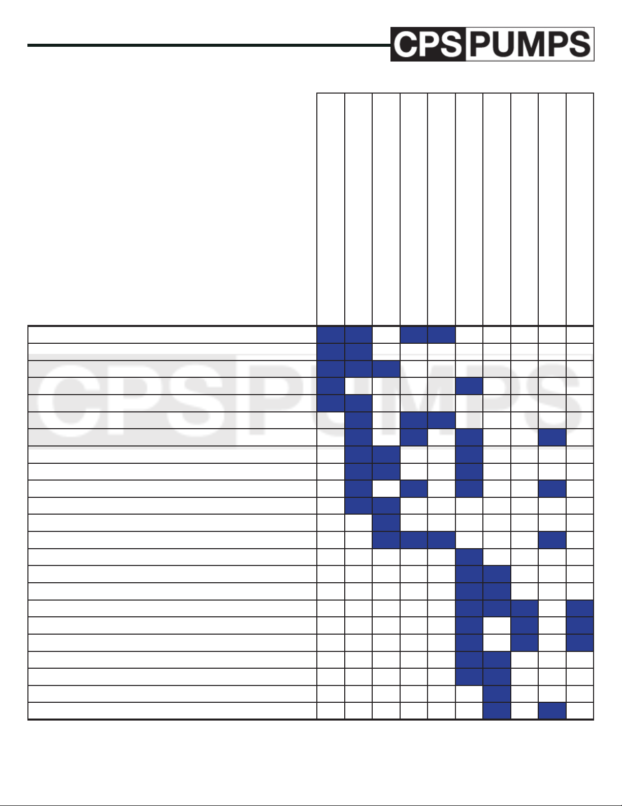
PROBLEM
Suction lift too high
Discharge head too high
Rotational speed too low
Incorrect direction of rotation
Impeller plugged/impeller partially blocked by debris
Air leak in discharge line
Insucient Net Positive Suction Pressure Available (NPSH
Damaged impeller
Defective packing
Inlet pipe not submerged enough
Impeller diameter too small
Obstruction in water passageways
Entrained air or gas in liquid
Discharge head lower than previously thought
Specic gravity of liquid higher than previously thought
Viscosity of liquid higher than previously thought
Bent or damaged shaft
Bearings worn
Misalignment of pump and driver
Defect in driver
Voltage and/or frequency lower than previously thought
Rotor assembly binding
Rotational speed too high
POSSIBLE EFFECT
No liquid delivered
Not enough liquid delivered
Not enough discharge pressure
Loss of liquid after starting
Pump operating for a short time, then stops
Pump is pulling high horsepower
Driver running hot
Excessive vibration
Cavitation noise from pump
Pump bearings running hot
A)
IOM Manual: IOM-0000-CST IOM
Series CST: Submersible Turbine
01/01/2018 - Edition 1A
15
www.cps-pumps.com
Page 16
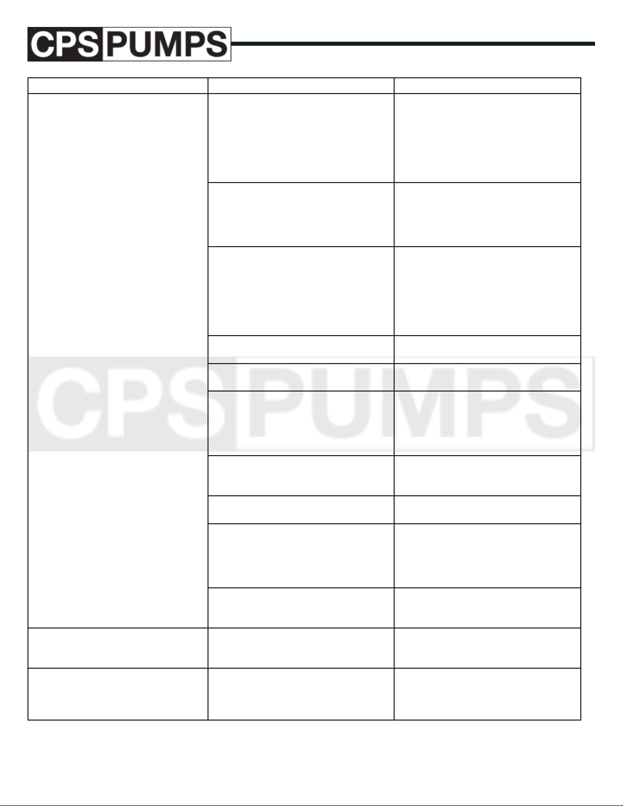
PROBLEM POSSIBLE CAUSE RECOMMENDED REMEDY
Problem #1
Pump not reaching design ow rate.
1.1
Insucient NPSH
present)
A. (Noise may not be
Recalculate NPSH available. It must
be greater than the NPSH required by
pump at desired ow. If not, redesign
suction piping, holding number of
elbows and number of planes to a minimum to avoid adverse ow rotation as it
approaches the impeller.
1.2
System head greater than anticipated.
Reduce system head by increasing pipe
size and/ than or reducing number of
ttings. Increase impeller diameter.
NOTE: Increasing impeller diameter
may require use of a larger motor.
1.3
Entrained air.
Air leak from atmosphere on suction
side.
1. Check suction line gaskets and
threads for tightness.
2. If vortex formation is observed in suction tank, install vortex breaker.
3. Check for minimum submergence.
1.4
Entrained gas from process.
1.5
Speed too low.
1.6
Direction of rotation wrong.
Process generated gases may require
larger pumps.
Check motor speed against design
speed.
After conrming wrong rotation,
reverse any two of three leads on a three
phase motor. e pump should be
disassembled and inspected before it is
restarted.
1.7
Impeller too small.
Replace with proper diameter impeller.
NOTE: Increasing impeller diameter
may require use of a larger motor.
1.8
Replace impeller and/or case wear rings.
Impeller clearance too large.
1.9
Plugged impeller, suction line or casing
which may be due to large solids.
1. Reduce length of suction when possible.
2. Reduce solids in the process uid
when possible.
3. Consider larger pump.
1.10
Replace part or parts.
Wet end parts (bowl, impeller) worn,
corroded or missing.
Problem #2.0
Pump not reaching design head
(TDH).
Problem #3.0
No discharge or ow
2.1
Refer to possible causes under Problem
#1.0.
3.1
Not properly primed.
Refer to remedies listed under Problem
#1.0 and #3.0.
Repeat priming operation, recheck
instructions. If pump has run dry, disas-
semble and inspect the pump before
operation.
www.cps-pumps.com
16
IOM Manual: IOM-0000-CST
Series CST: Submersible Turbine
01/01/2018 - Edition 1A
Page 17
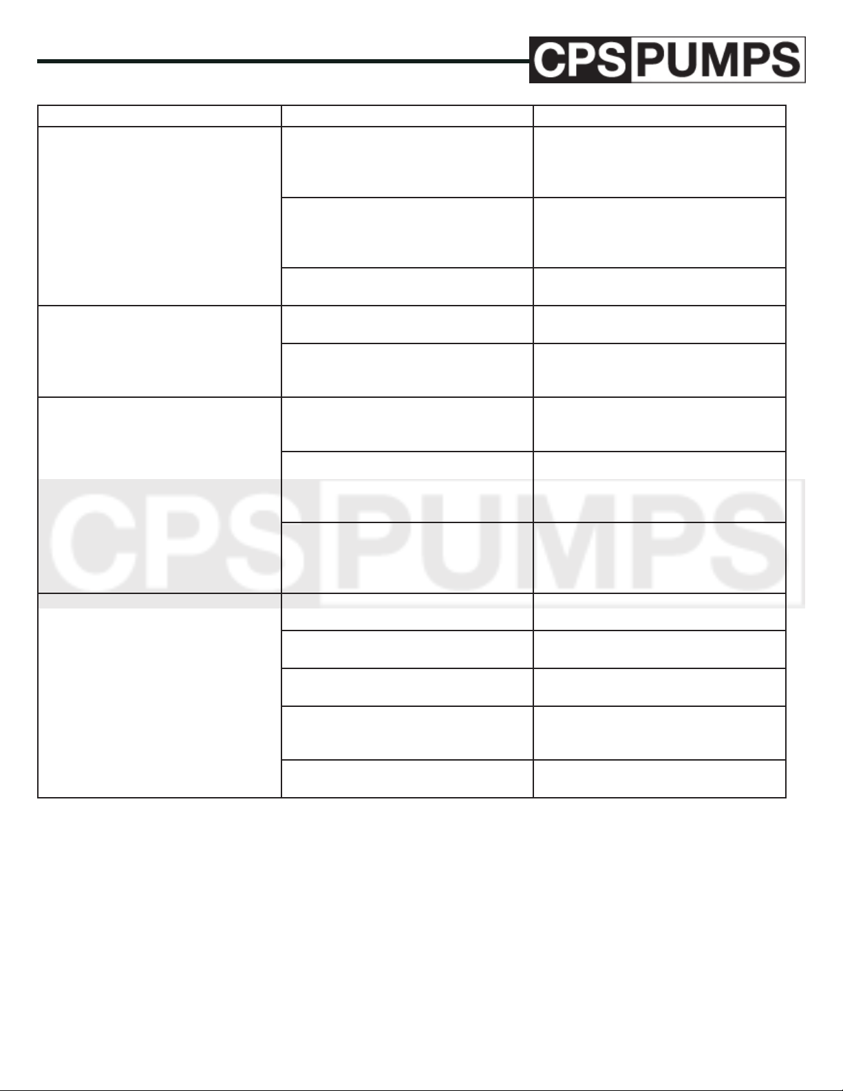
PROBLEM POSSIBLE CAUSE RECOMMENDED REMEDY
Cont. Problem #3.0
No discharge or ow
3.2
Direction of rotation wrong.
After conrming wrong rotation,
reverse any two of three leads on a three
phase motor. e pump should be disas-
sembled and inspected before operation.
3.3
Plugged impeller, suction line or casing
Refer to recommended remedy under
Problem #1.0, Item #1.9.
which may be due to a brous product
or large solids.
3.4
Replace damaged parts.
Damaged pump shaft, impeller.
Problem #4.0
Pump operates for short period, then
loses prime.
4.1
Insucient NPSH
4.2
Entrained air.
A.
Refer to recommended remedy under
Problem #1.0, Item #1.1.
Air leak from atmosphere on suction
side. Refer to recommended remedy
under Problem #1.0, Item #1.1.
Problem #5.0
Excessive noise from wet end.
5.1
Cavitation - insucient NPSH avail-
Refer to recommended remedy under
Problem #1.0, Item #1.1.
able.
5.2
Abnormal uid rotation due to complex
suction piping.
Redesign suction piping, holder number
of elbows and number of planes to a
minimum to avoid adverse uid rotation
as it approaches the impeller.
5.3
Impeller rubbing.
1. Replace impeller and/or case wear
rings.
2. Check outboard bearing assembly for
axial end play.
Problem #6.0
Pump will not run.
6.1
No power to control box.
6.2
Refer to ELECTRICAL TESTS
Refer to ELECTRICAL TESTS
Motor protection device tripped.
6.3
Refer to ELECTRICAL TESTS
Blown fuse.
6.4
Refer to ELECTRICAL TESTS
Open circuit in cable, splice or motor
winding.
6.5
Refer to ELECTRICAL TESTS
Control box malfunction.
IOM Manual: IOM-0000-CST IOM
Series CST: Submersible Turbine
01/01/2018 - Edition 1A
17
www.cps-pumps.com
Page 18
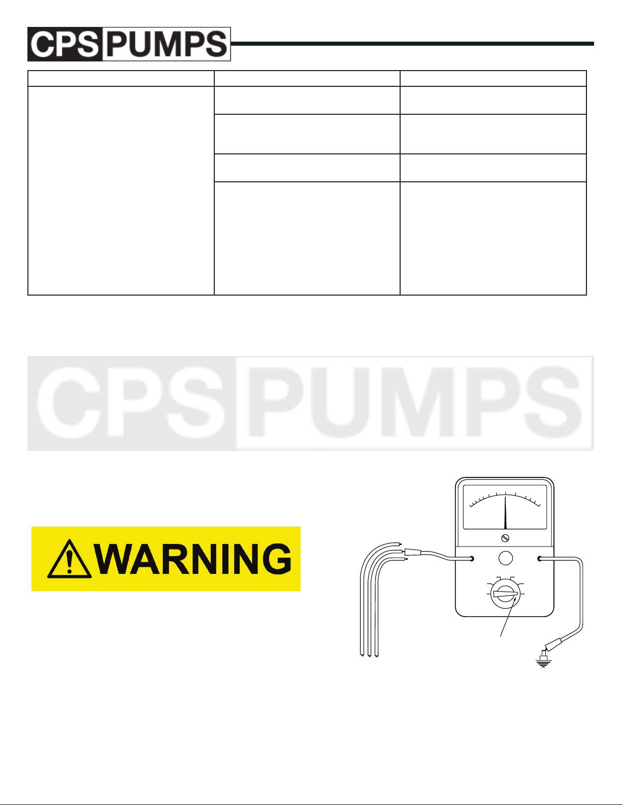
PROBLEM POSSIBLE CAUSE RECOMMENDED REMEDY
Problem #7.0
Overload Protector Trips
7.1
Incorrect control box.
7.2
Incorrect, loose or corroded electrical
Replace with correct control box.
Replace defective item. Refer to ELECTRICAL TESTS.
connections.
7.3
Correct line voltage.
Incorrect voltage.
7.4
Current overload.
Check for:
1. Tight motor or pump bearing.
2. Pump clogged with sand.
3. Unbalanced voltage.
4. Grounded cable, splice or motor
winding. Refer to ELECTRICAL
TESTS.
5. Low Voltage.
6. Insucient cooling of motor.
ELECTRICAL TESTS
MEASURING INSULATION RESISTANCE (GROUND TEST)
e condition of the insulation around a conductor can be
determined by measuring the electrical resistance between the
conductor and ground. is measurement can be made with
a meggar or an ohm-meter. e value is stated in ohms or
megohms (ohms x 1,000,000). High ohm values indicate good
insulation.
e basic procedure for measuring insulation resistance is given
below:
Turn o all power and disconnect the leads to be tested from the
electrical panel.
Failure to turn o the power will damage the meter and can cause
serious or fatal shock.
Do not touch any bare wires or allow bare wires to come in contact with the ground or metal. False readings will result.
If the meter needle is at either extreme end of the scale, a more
accurate reading can be obtained by switching the selector
switch to another scale. Re-zero the meter each time the selector switch is moved.
e readings obtained from drop cables and motor leads should
be within the range specied in FIGURE 5. Low readings
indicate that the motor windings are grounded or that the cable
or splice insulation is damaged. If low or marginal readings are
obtained on a new installation the problem should be corrected
before proceeding with the installation.
10
5
20
25
R x 10
OHMS
R x 100
R x 1
OHMS
2
0
ZERO
R x 1000
R x 10K
R x 100K
Failure to disconnect the leads can result in false readings.
Set the meter selector knob to RX 100K or RX 100,000. (Some
meters may not have RX 100K in which case RX 10K or RX
10,000 scale can be used.) Clip the meter leads together and
adjust the meter to zero.
Unclip the leads and attach them. See FIGURE 4.
www.cps-pumps.com
SET SELECTOR
KNOB AT
DROP CABLE
R x 100K
OR
MOTOR LEADS
FIGURE 4 – Measuring Insulation Resistance
18
IOM Manual: IOM-0000-CST
Series CST: Submersible Turbine
GROUND
01/01/2018 - Edition 1A
Page 19
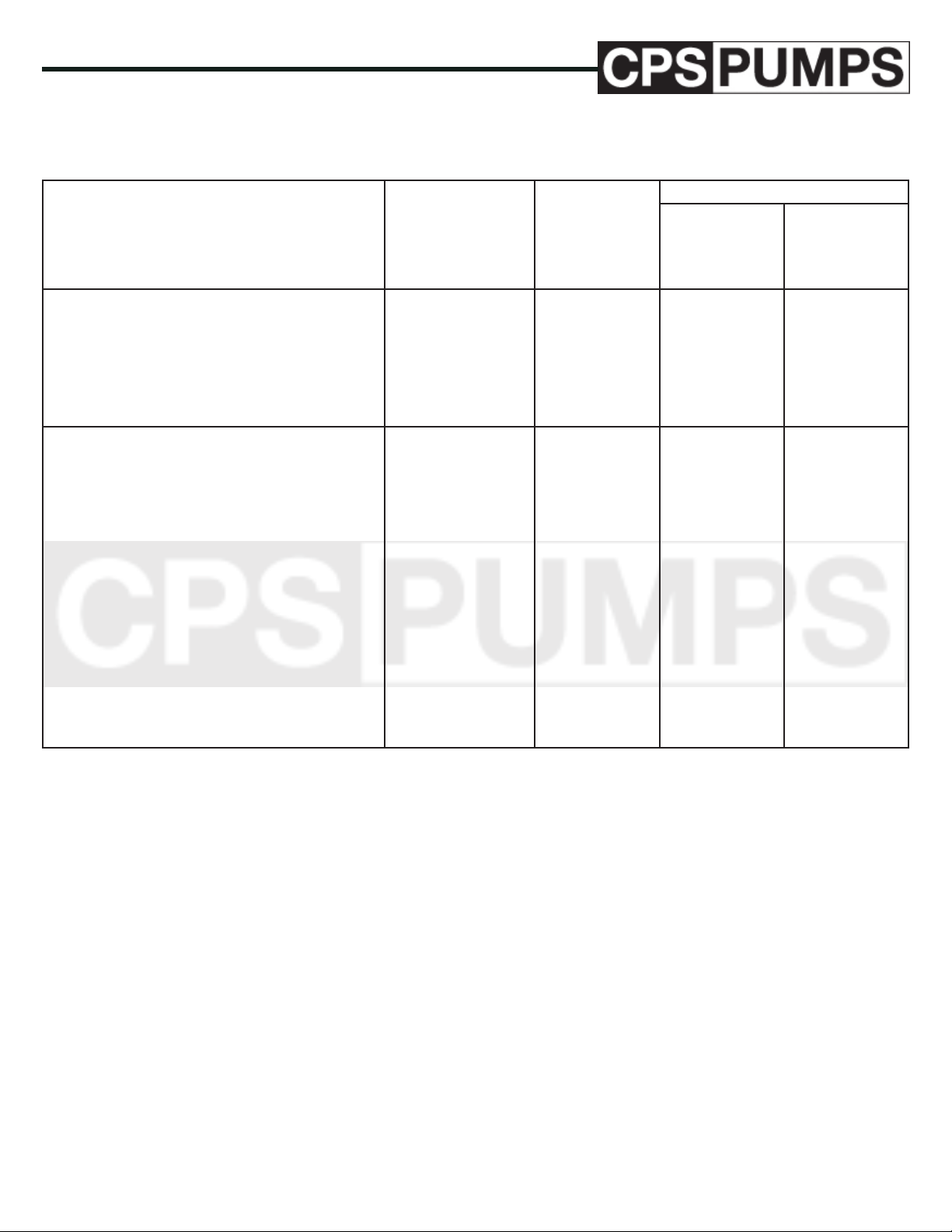
Insulation resistance does not vary with rating. All motors of all
HP, voltage and phase rating have the same insulation resistance ranges.
CONDITION OF MOTORS AND LEADS OHMS MEGOHMS
BENCH TESTS
METER READING
R x 100K
or
R x 100,000
scale
R x 10K
orR x 10,000
scale
• A new motor (without drop cable)
• A used motor which can be reinstalled in the
well
• Cable splice after immersion for one hour in
water
WELL TESTS (ohm readings are for drop cable
plus motor)
• A new motor or used motor in good condition.
• A motor in reasonably good condition.
500,000-2,000,000
• A motor which may have been damaged by
lightning or with damaged leads. Do not pull the
pump for this reason.
• A motor which denitely has been damaged
or with damaged cable. e pump should be
pulled and repairs made to the cable or the motor
replaced. e motor will not fail for this reason
alone, but will probably not operate for long.
• A motor which has failed or with completely
less than 10,000
destroyed cable insulation. e pump must
be pulled and the cable repaired or the motor
replaced.
+ Indicates that the reading should be the value shown or
greater. Higher readings indicate better insulation.
20,000,000+
10,000,000+
2,000,000+
2,000,000 +
20,000-500,000
10,000-20,000
0.5-2.0
0.02-0.5
0.01-0.02
0-0.01
20+
10+
2+
2+
200+
100+
20+
20+
5-20
0.2-5
0.1-0.2
0-0.1
2000 + or 2K +
1000 + or 1K +
200+
200+
50-200
2-50
1-2
0-1
FIGURE 5 – Nominal Insulation Resistance Values Between
All Legs & Ground
IOM Manual: IOM-0000-CST IOM
Series CST: Submersible Turbine
01/01/2018 - Edition 1A
19
www.cps-pumps.com
Page 20
MEASURING RESISTANCE BE-
OHMS
ZERO
OHMS
DROP CABLE
OR
MOTOR LEADS
GROUND
SET SELECTOR
KNOB AT
R x 100K
R x 100K
R x 1
R x 10
R x 100
R x 1000
R x 10K
10
20
25
5
2
0
TWEEN LEADS (MOTOR WINDING RESISTANCE)
e general condition of motor windings can be deter- mined
by measuring the resistance of the motor windings (i.e. the resistance between the motor leads) and comparing the measured
resistance with values given in the motor manual. e resistance
is measured with an ohm-meter and the value is stated in ohms.
e basic procedure for measuring motor winding resistance is
given below.
Turn o the power and disconnect the leads to be tested from the
panel.
Failure to turn o the power will damage the meter and can
cause serious or fatal shock.
Failure to disconnect the leads can result in false readings.
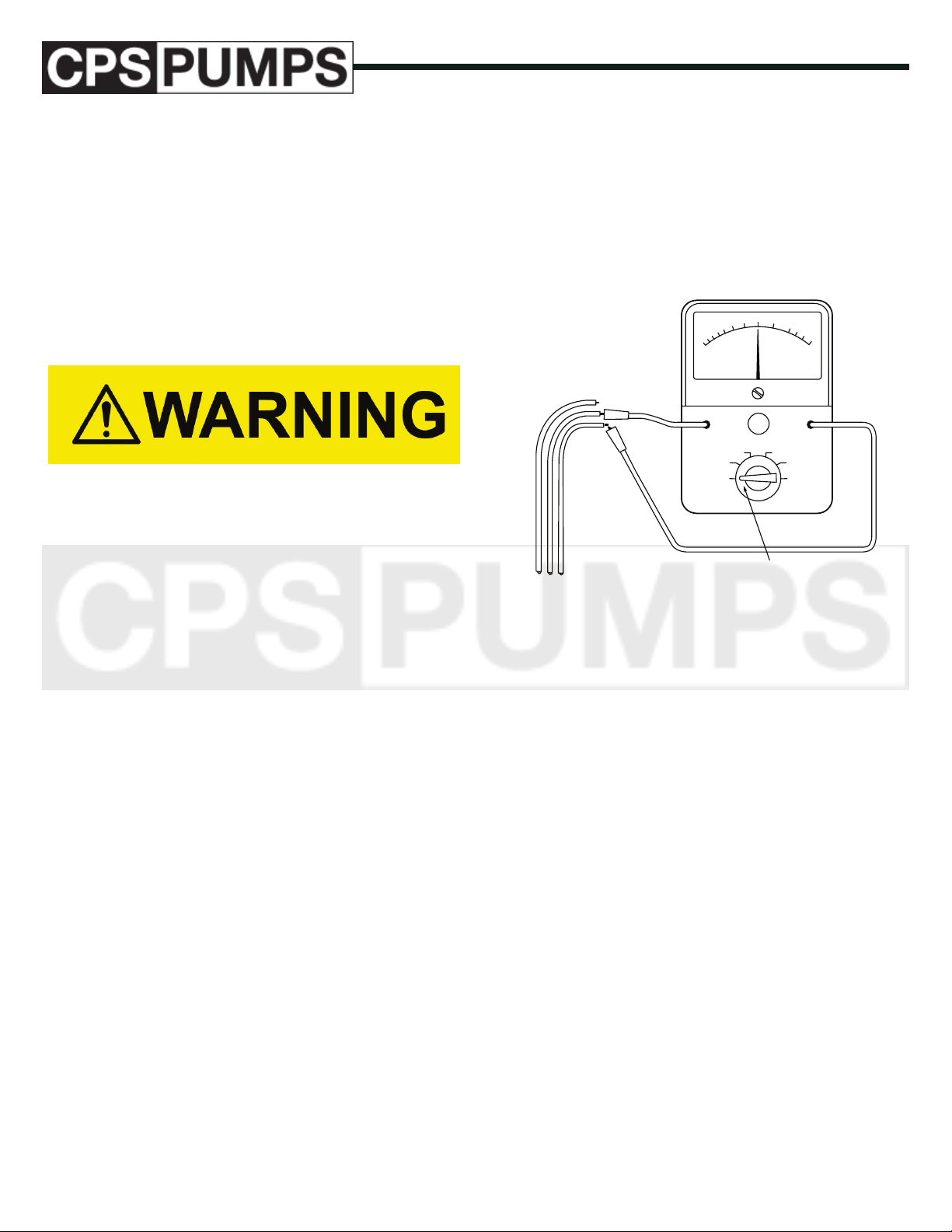
Set the meter selector knob to “Ax 1 “. Clip the meter leads
together and ad-just the meter to zero.
Unclip the leads and attach them. See FIGURE 6.
Resistance measured between the motor leads prior to splicing
the drop cable to the motor leads should be within the motor winding resistance limits specied in the motor manual.
Resistance measured between the drop cable leads after splicing
the drop cable to the motor leads will indicate the resistance of
the drop cable plus the motor windings. e motor winding resistance is obtained by the formula below. e calculated value
should be within the limits specied in the motor manual.
Motor winding resistance reading measured at drop cable from
FIGURE 6.
A higher winding resistance than shown in the motor manual
indicates a possible burned (open) winding, an open cable, a
loose connection or the wrong motor (dierent HP or voltage
than readings being referenced).
A considerably lower winding resistance than shown in the
motor manual indicates a possible shorted (burned together)
winding or the wrong motor.
Unequal resistance between the windings on a three phase motor indicates a burned winding or a faulty connection.
e values below are for copper conductors. If aluminum conductor drop cable is used, the resistance will be higher for each
foot of cable of the same size. To determine the actual resistance of aluminum drop cable, divide the ohm readings from
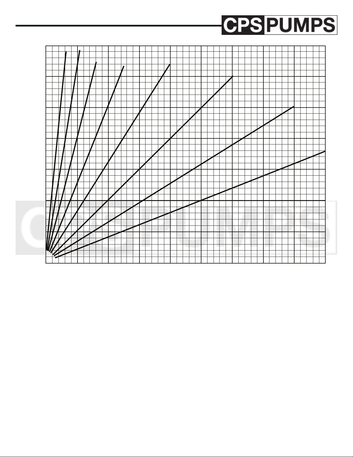
this chart by 0.61. is chart shows total resistance of cable
from control box to motor and back.
OHMS
ZERO
OHMS
R x 10
R x 100
R x 1
R x 1000
R x 10K
R x 100K
SET SELECTOR
DROP CABLE
KNOB AT R x 1
OR
MOTOR LEADS
SINGLE PHASE, 2 WIRE - MEASURE BETWEEN TWO WIRES
SINGLE PHASE, 3 WIRE - MEASURE BETWEEN BLACK AND
YELLOW AND THE MEASURE
BETWEEN RED AND YELLOW
THREE PHASE - MEASURE BETWEEN EACH PAIR, AB, AC
FIGURE 6 – Measuring Winding Resistance
C. CURRENT UNBALANCE TEST
For three phase units, THE CURRENT UNBALANCE
BETWEEN LEGS OF THE POWER SUPPLY SHOULD
NOT EXCEED 5%. Current unbalance is determined by measuring the amperage in each of the three legs and then calculating the percent current unbalance using the formula below. is
calculation must be performed using each of the three hookups
shown.
THE HOOKUP THAT RESULTS IN THE LOWEST PERCENT CURRENT UNBALANCE SHOULD BE USED
FOR THE FINAL CONNECTION OF THE POWER
LEADS. is procedure is commonly known as “rolling the
leads”. To prevent changing the motor rotation, be careful to
follow the hookups shown below very carefully. A worksheet
and sample calculation are given. See FIGURE 7.
www.cps-pumps.com
20
IOM Manual: IOM-0000-CST
Series CST: Submersible Turbine
01/01/2018 - Edition 1A
Page 21
1500
DROP CABLE OHMS
PUMP
SETTING
(FEET)
1250
#4 CABLE
#2 CABLE
#6 CABLE
#8 CABLE
1000
#0 CABLE
750
500
250
0
FIGURE 6 – Drop Cable Resistance
#10 CABLE
#12 CABLE
#14 CABLE
.5 1.0 1.5 2.0 2.5
3.0 3.5 4.0 4.5
IOM Manual: IOM-0000-CST IOM
Series CST: Submersible Turbine
01/01/2018 - Edition 1A
21
www.cps-pumps.com
Page 22
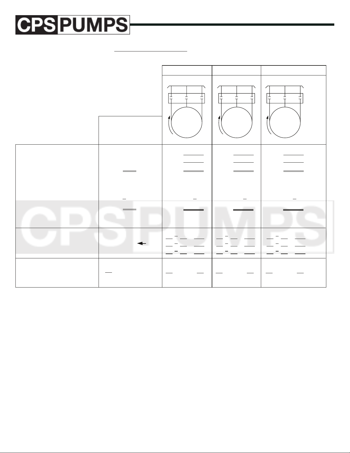
Percent Current Unbalance =
max. current difference in any
leg from average current
average current
x 100
• Measure current in
each leg.
• Add leg currents to
determine total current.
• Calculate average leg
current.
• Determine max. difference
of any one leg from
the average.
1st Hook Up
L1
Sample
Calculation
T1 L1 51 amps
T2 L2 46 amps
T3 L3 53 amps
T1 L1
T2 L2
T3 L3
150 amps
.
3
.
50 amps
51 - 50 = 1
50 - 46 = 4
max.
53 - 50 = 3
2nd Hook Up 3rd Hook Up
L2 L3 L1 L2 L3 L1 L2 L3
T1
T2
T3
T2A
.
3
.
=
=
=
T3
T3 L1
T1 L2
T2 L3
T1
T2
T2
T2B T2C
T2 L1
T3 L2
T1 L3
.
3
.
=
=
=
T3
SUPPLY
STARTER
T1
MOTOR
.
3
.
=
=
=
• Calculate percent
unbalance using
formula above.
4 x 100 = 8%
50
THE MAXIMUM ALLOWABLE UNBALANCE IS 5%.
FIGURE 7 – Load Datasheet
Since loads on a transformer bank may vary during the day,
readings should be taken at least twice; once during the day at
what would be considered the normal load period and once in
the evening during the usual peak load period.
e leads should then be connected for the lowest percent current unbalance during the period that the pump will operate the
most.
By observing where the highest current reading is for each leg of
each of the hookups, the cause of the unbalance can be determined. If the high current leg is always on the same power leg
L, this indicates that most of the unbalances from the power
source. If the high current is always on the same motor lead T,
www.cps-pumps.com
x 100 = %
this indicates that the motor or a poor connection is causing
most of the unbalance.
If the current unbalance still exceeds 5% after rolling the leads
and connecting them for the lowest unbalance, the pump should
be stopped and corrective action taken. e power company
should be contacted for assistance.
x 100 = % x 100 = %
ASSEMBLY OF PUMP AND
MOTOR
e size and length of the pump/motor assembly will determine
whether the pump and motor can be assembled in the shop or
must be assembled in the vertical position at the well site. Very
large units or long units with many stages must be assembled at
the well site.
22
IOM Manual: IOM-0000-CST
Series CST: Submersible Turbine
01/01/2018 - Edition 1A
Page 23
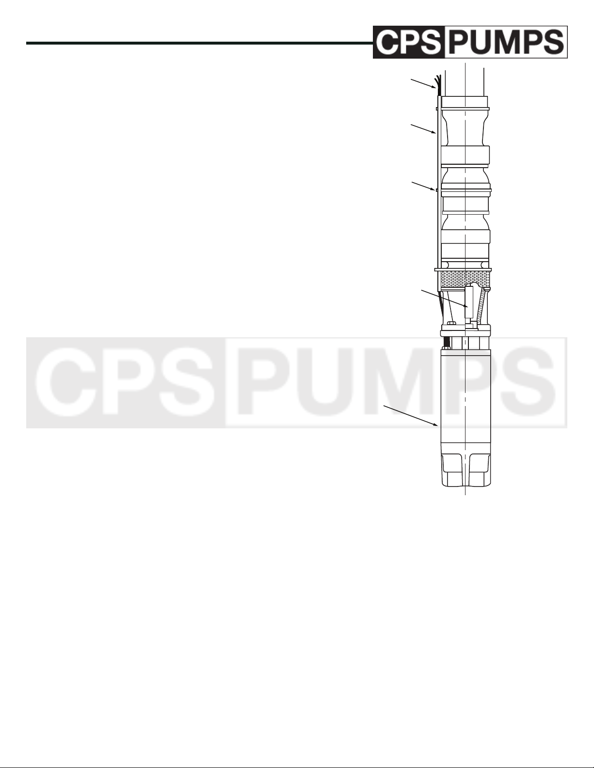
Do not use the motor leads to lift or handle the motor. e
SHAFT COUPLIN
motor leads are easily damaged. ey should be protected and
handled with care at all times.
Consult the motor manual and perform any pre-installation
servicing of the motor that is required. Some motors will require lling with oil or water.
If the motor is to be assembled to the pump while in the shop,
go to Step 3 below. If the motor is to be assembled at the well
site, perform the ELECTRICAL TESTS on page 18 while the
motor is still in the shop. Be careful to protect the motor leads
during transportation of the motor to the well site.
Check that the pump shaft and motor shaft turn freely.
Clean the exposed portion of the pump shaft and motor shaft.
Clean the ange faces and registers on the pump and motor
mating anges. Remove all burrs from these areas.
MOTOR LEADS
MOTOR LEADS
SHIELD
BAND-IT STRAP
Install the key in the motor shaft. See FIGURE 8. Splined
motor shafts do not use a key.
If the shaft coupling has set screws in motor shaft half of the
coupling, loosen or remove these set screws.
Align the motor with the pump and slide the motor shaft into
the shaft coupling on the pump. Be careful not to damage the
shaft, the coupling, or the key. Orient the motor so that the
motor leads are aligned with the notch provided in the pump
mounting ange. Install and tighten the mounting bolts (or
capscrews).
If the shaft coupling has set screws in the motor shaft half of the
coupling, pull the coupling toward the motor until the shafts
butt and then install and tighten the set screws on the motor
end of the coupling.
Install a shield over the motor leads to prevent damaging the
leads when lowering the pump into the well. A channel shaped
metal shield held in place with 1/2” wide stainless steel “BandIt” straps is recommended. e shield should be installed as
shown in FIGURE 8 with the lower end positioned immediately above the suction inlet, the upper end at the top of the
discharge case (or check valve) and straps located as shown.
Test the completed pump/motor assembly per the ELECTRICAL TESTS on page 18. Ignore this step if the pump was
assembled at the well site.
G
MOTOR
FIGURE 8 – Typical Pump/Motor Assembly
UPTHRUST ADJUSTMENT
PUMPS WITH 4” AND 6” MOTORS
e impeller up-thrust has been preset to mount the pump end
to the motor. e total amount of upward axial movement must
be 0.125 inches. To adjust, loosen the hex nut at the discharge
end plug and then adjust the stud to obtain the proper up-thrust
limit. Tighten the hex nut to lock into place. See FIGURE 9.
IOM Manual: IOM-0000-CST IOM
Series CST: Submersible Turbine
01/01/2018 - Edition 1A
23
www.cps-pumps.com
Page 24
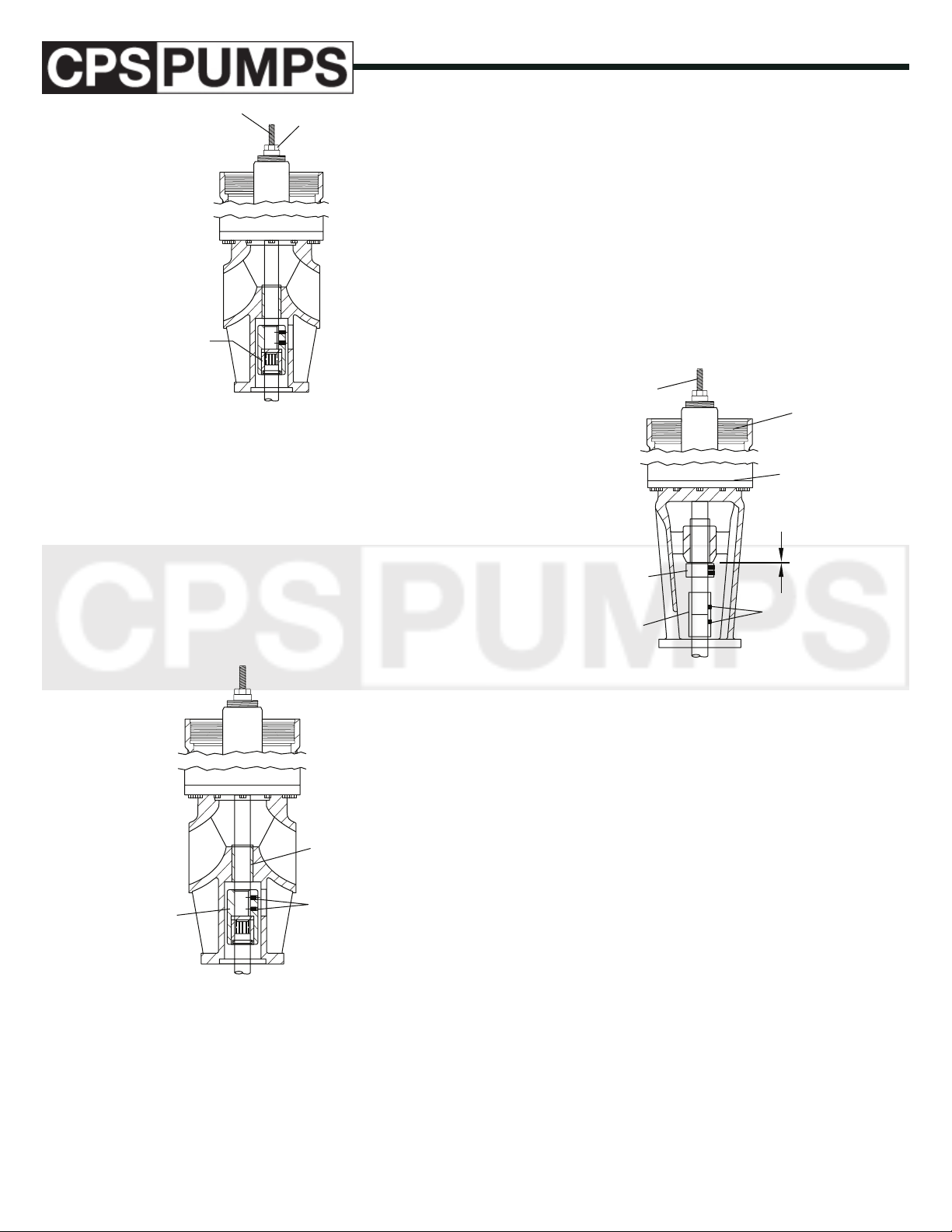
ADJUSTING STUD
COUPLING
HEX NUT
PUMPS WITH 6”, 8”, 10”, 12”, 14”
AND 16” MOTORS (OPEN BEARING STYLE)
e impeller up-thrust must be checked and adjusted after motor installation. With the pump end mounted to the motor, the
total amount of upward axial movement must be 0.125 inches.
To adjust, loosen the hex nut at the discharge end plug and then
adjust the stud to obtain the proper up-thrust limit. Tighten
the hex nut to lock into place. Loosen the set screw in the
thrust collar, obtain the proper up-thrust limit and re-tighten
the set screws. See FIGURE 11.
HEX NUT
ADJUSTING STUD
TOP
FIGURE 9 – Up-thrust Adjustment
PUMPS WITH 8” MOTORS
e impeller up-thrust must be checked and adjusted after motor installation. With the pump end mounted to the motor, the
total amount of upward axial movement must be 0.125 inches.
To adjust, loosen the hex nut at the discharge end plug and then
adjust the stud to obtain the proper up-thrust limit. Tighten
the hex nut to lock into place. See FIGURE 10.
LOWER PUMP
BEARING
COUPLING
SET SCREWS
BOTTOM
0.125Ó
THRUST COLLAR
SET SCREWS
COUPLING
FIGURE 11 – Up-thrust Adjustment
SPARE PARTS
RECOMMENDED SPARE PARTS
e decision on what spare parts to stock varies greatly depending on many factors such as the criticality of the application,
the time required to buy and receive new spares, the erosive/
corrosive nature of the application, and the cost of the spare
part. Please refer to the “CPS-Pumps Parts Catalog” for more
information.
FIGURE 10 – Up-thrust Adjustment
www.cps-pumps.com
HOW TO ORDER SPARE PARTS
Spare parts can be ordered from the local CPS-Pumps Sales
Engineer, or from the CPS-Pumps Distributor or Representative. e pump size and type can be found on the name plate
on the discharge head or suction bell. See FIGURE 1. Please
provide the item number, description, and alloy for the part(s)
to be ordered.
To make parts ordering easy, CPS-Pumps has created a catalog
24
IOM Manual: IOM-0000-CST
Series CST: Submersible Turbine
01/01/2018 - Edition 1A
Page 25

titled “CPS-Pumps Parts Catalog.” A copy of this book can be
obtained from the local CPS-Pumps Sales Engineer or Distributor/Representative.
IOM Manual: IOM-0000-CST IOM
Series CST: Submersible Turbine
01/01/2018 - Edition 1A
25
www.cps-pumps.com
Page 26
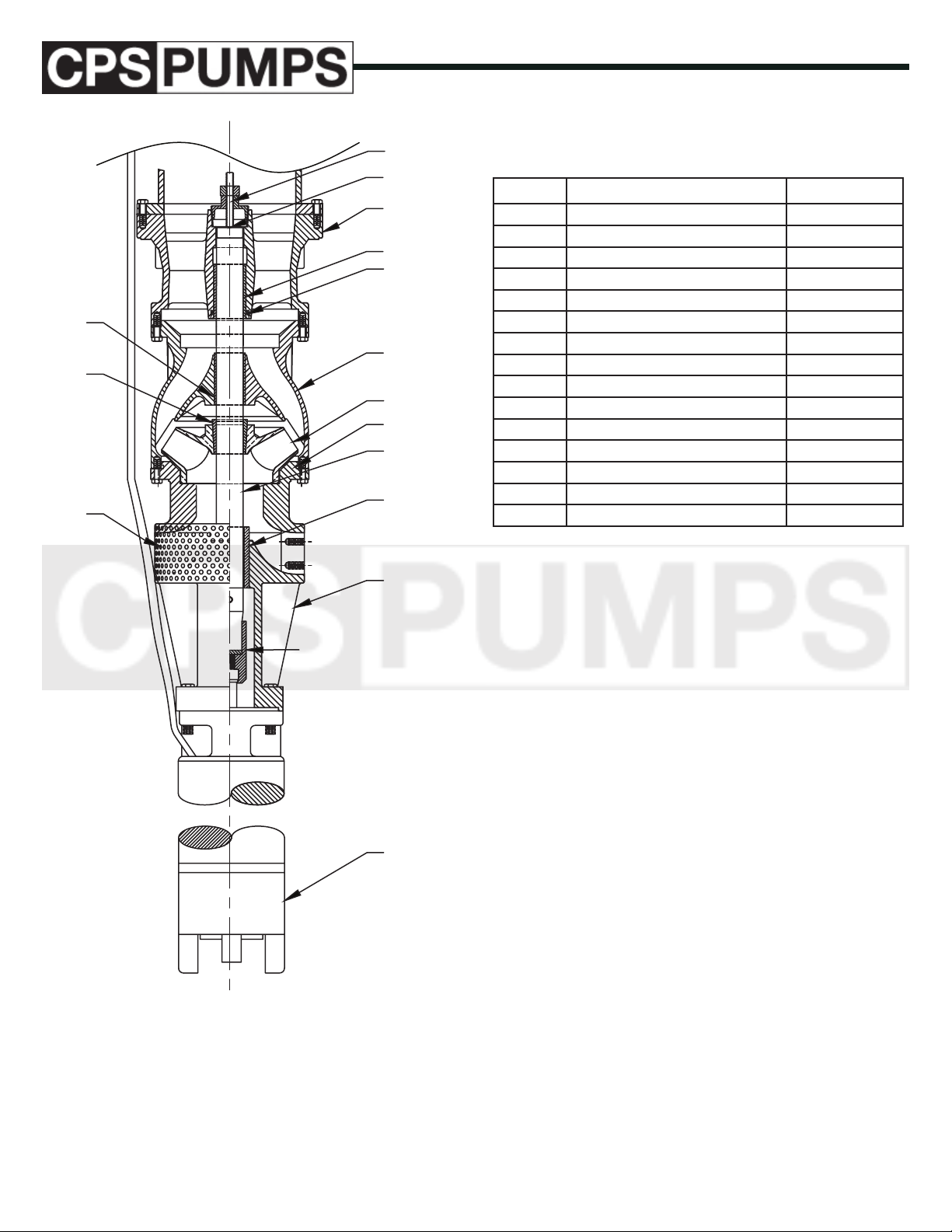
136B
225
006006
616D
256D
302
136D
364L
179
444
364
728B
136S
816
SUBMERSIBLE TURBINE
BOWL ASSEMBLY
ITEM DESCRIPTION MATERIAL
006 SUCTION SCREEN 300 SS
136B BOWL BEARING BRONZE
136D DISCHARGE CASE BEARING BRONZE
136S SUCTION CASE BEARING BRONZE
179 BOWL CAST IRON
225 IMPELLER COLLET CARBON STEEL
256C MOTOR COUPLING 416 SS
256D UPTHRUST DISC 300 SS
302 DISCHARGE CASE DUCTILE IRON
364 BOWL O-RING VITON
364L LIP SEAL RUBBER
444 IMPELLER 304 SS
616D DISCHARGE CASE PLUG CARBON STEEL
728B BOWL SHAFT 416 SS
816 SUCTION CASE CAST IRON
REFER TO FACTORY FOR OPTIONAL METALLURGY AND LEAD-TIMES
ALL PRICES ARE F.O.B ROSSVILLE, TN AND SUBJECT TO CHANGE
WITHOUT NOTICE
256C
MOTOR
www.cps-pumps.com
26
IOM Manual: IOM-0000-CST
Series CST: Submersible Turbine
01/01/2018 - Edition 1A
 Loading...