

CPS TEMP-SEEKER TM360A, TEMP-SEEKER TM360, TEMP-SEEKER TM360C Owner's Manual
TM360A AUTOMOTIVE TEMP-SEEKER
®
Precision Thermo-Psychrometer
Multi-Channel Air Conditioning Humidity and Temperature Drop Tester
OWNER’S MANUAL (English)
cpsproducts.com

2
Congratulations on your purchase of one of the best precision automotive AC diagnosis, testing
and repair tools available! CPS Products TM360A TEMP-SEEKER® is a high resolution thermopsychrometer adaptable to accommodate all your temperature, humidity, dry/wet bulb and dew point
measurements. The instrument offers 4 separate temperature channels for high accuracy thermistor
probes, and an auxiliary port to connect a state-of- the-art solid state RH/DB probe.
The TM360A memory functions continuously store MIN & MAX readings from all temperature input
ports. Pressing SCAN key will toggle the display between all four temperature input ports in three
second intervals, providing continuous monitoring of multiple probe points during critical system
diagnosis. The unit has an illuminated, low power LCD making it easy to take readings both in poorly
illuminated areas and in bright sunlight. It also has a provision to connect to an optional external
power adapter to conserve battery life during extended monitoring situations.
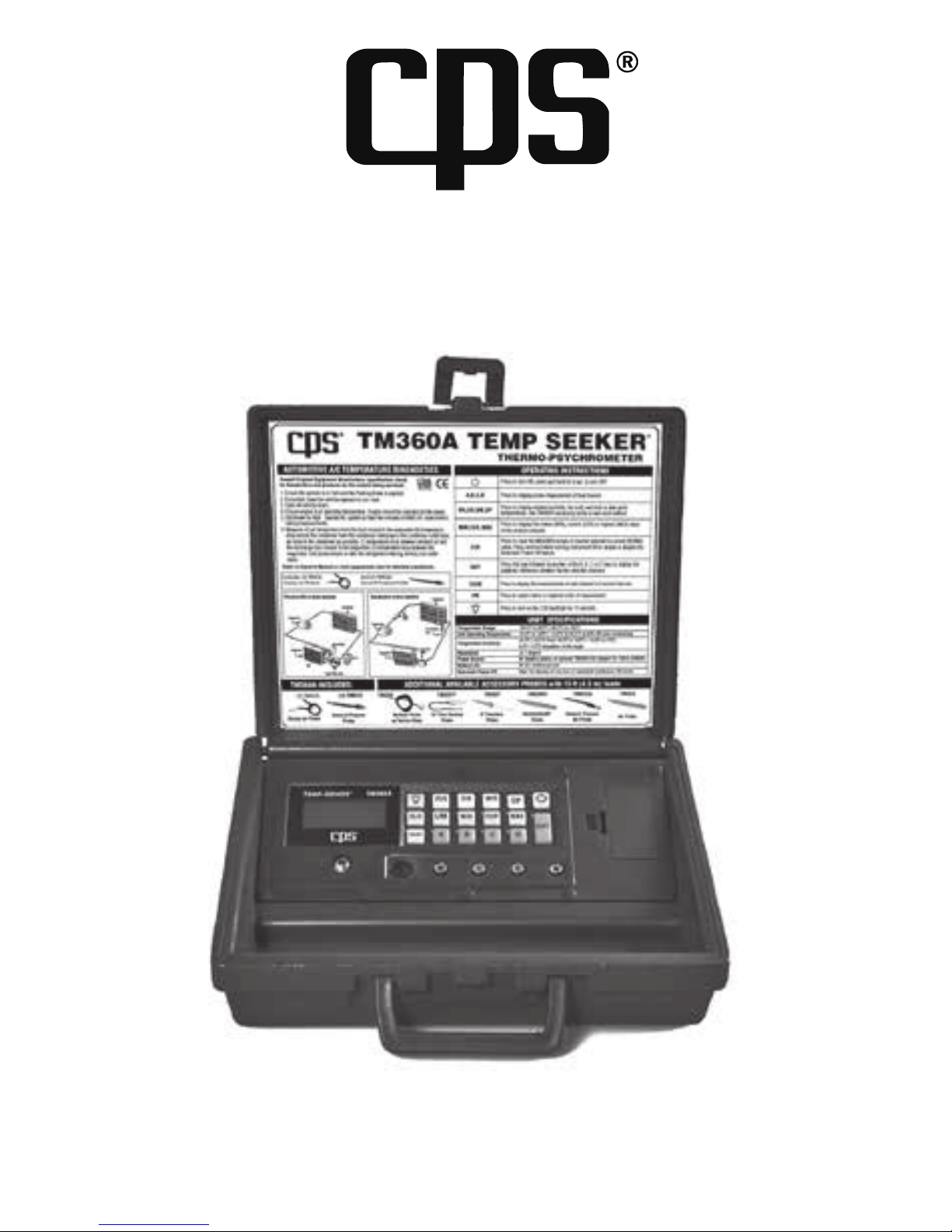
Designed in a rugged blow-molded polyethylene case, the TM360A is engineered to provide laboratory
accuracy in rough shop/field environments. A generous probe storage area is provided to keep all
your job-specific probes neatly housed. Note: Probes can remain plugged in during storage, reducing
life-shortening stress on both
the connection ports and the probe connector ends.
TABLE OF CONTENTS
OVERVIEW
Overview .................................................. 2
Specifications ............................................ 3
Safety Precautions ..................................... 3
Operation .............................................. 4-6
TMX3RH Method .............................. 7
Wet-Sock Method ............................. 7
Psychrometric Chart ................................ 8
Automotive Overview ............................... 9
Automotive AC Temperature Diagnostic
.... 10
Technician Operating Tips ...................... 11
Sample Performance Charts ................... 12
Standard Orifice Tube System Test .......... 13
Variable Displacement Compressors........ 13
Accessory Probes / Accessories .........14-16
APPENDIX
Condenser Flow Chart A ................... 17
Air Efficiency Flow Chart B ................ 18
Evaporator Flow Chart C ................... 19
Warranty .................................................. 20
• Four discrete temperature channels
• High accuracy silicon humidity transducer
probe port
• Large, 4-digit, easy-to-read, backlit LCD
(Liquid Crystal Display)
• Min/Max & memory functions
• Temperature differential between any two
of the four temperature ports
• Direct relative humidity and wet bulb
measurements
• Calibrated to NIST traceable standards
• Auto-off after ten minutes of non-use or
continuous ON mode
• Operates thirty continuous hours on one
9V alkaline battery
• Integrated battery eliminator jack
• Rugged polyethylene blow-molded case
• Large probe storage area
• Probes can remain plugged in to reduce
jack/probe wear
• Switchable °C/°F
• One year warranty
FEATURES

Resolution
±0.1˚F or ˚C
Temperature Accuracy
±0.4˚F / ±0.2˚C from 14.0 to 158˚F / -10.0 to 70˚C; 0.6˚F / 0.3˚C
elsewhere in the range
RH Range
0 to 100%RH
RH Accuracy (TMX3RH)
±1.8%RH from 10 to 90%RH; ± 3% elsewhere in the range
DB Accuracy (TMX3RH)
±1.2% of reading ± 1.0˚F from -40˚F to 200˚F (± 1.2% of reading ±
0.5˚C from -40˚C to 90˚C)
Power Source
9V alkaline battery or optional TMX3PS AC adapter for
100 to 240VAC (40 to 60 Hz)
Battery Life
30hrs. continuous use
Automatic Power Off
After 10 minutes of non-use or user selectable continuous
ON mode
Backlight
15 seconds
Dimensions
12" X 10" X 3" (30.5cm x 25.4cm x 7.6cm)
Weight
3lb (1.4 kg) with probes
Warranty
1 year
Always wear gloves
Always wear safety glasses
SPECIFICATIONS
SAFETY PRECAUTIONS
Safety Note: Test conditions place the AC system and vehicle sub-systems (engine cooling system
including both mechanical and electrical cooling fans, charging and fuel control systems) under
severe operating conditions when the cabin and ambient air temperatures exceed 80°F (27°C). Any
abnormalities should become quite evident, and safety must be held most important with regard
to continuing tests. If any unsafe condition exists, that must be addressed first, before any further
AC system testing is performed! Please refer to the Appendix at the back of this manual and use
copies of these documents for vehicle testing purposes: “Diagnostic Testing & Repair Verification
Worksheets” (DTRVWs) “Diagnostic Flow Charts” (DFCs)
Only qualified service personnel should operate this unit. Some
countries, states, etc…may require the user to be licensed. Please
check with your local government agency.
4
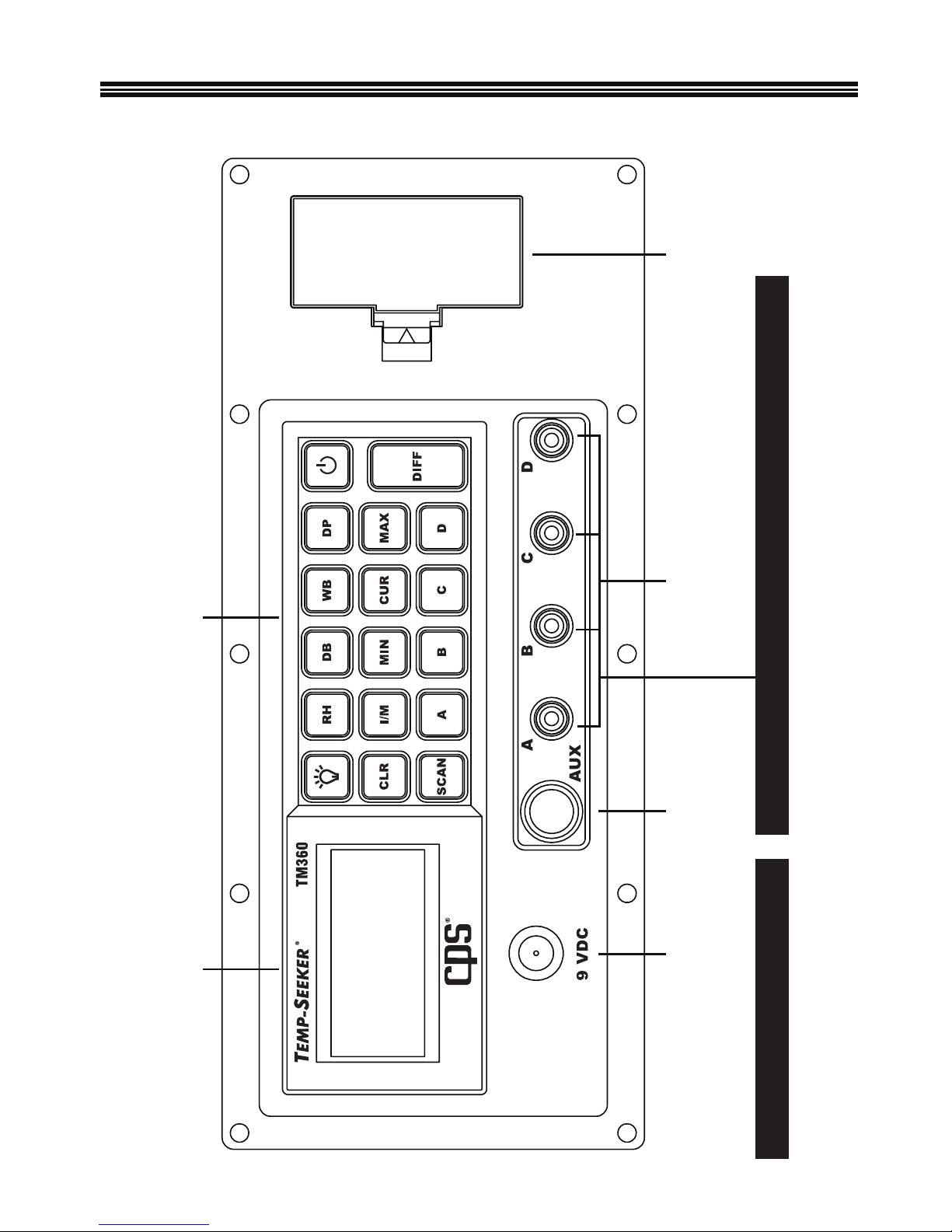
KeypadLCD Display
4 Temperature PortsRelative Humidity Port
(Indoor Air Quality)
Battery CompartmentBattery
Eliminator
Jack
TMX3PS - Optional Power Supply Default Wet Bulb Ports A & B (See Also Wet Sock Method on pg. 8)
OPERATION
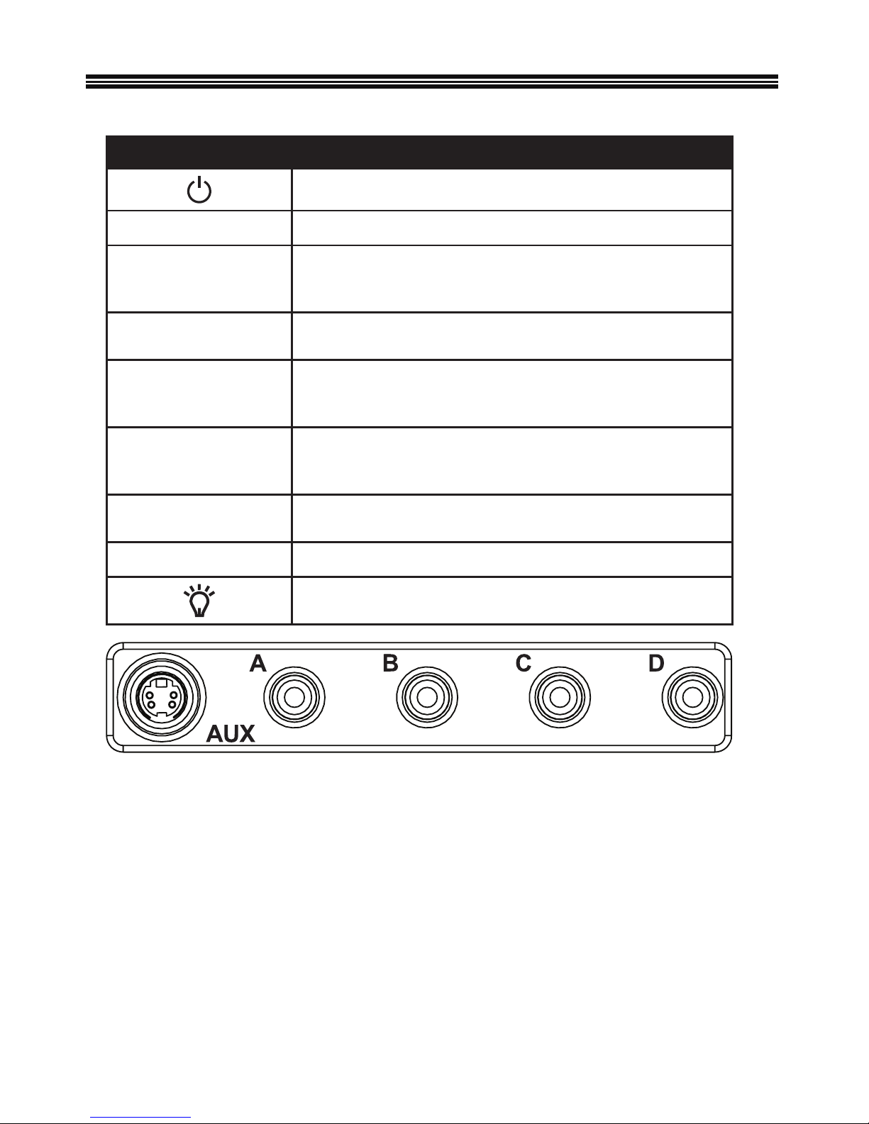
KEY FUNCTION
Press to turn ON, press and hold for 3 sec. to turn OFF
A, B, C, D Press to display probe measurement of that channel
RH,DB,WB,DP
Press to display relative humidity, dry bulb, wet bulb or dew
point temperatures. Use TMX3RH accessory probe or
wet-sock method
MIN,CUR,MAX
Press to display the lowest (MIN), current (CUR) or highest
(MAX) value of the channel selected
CLR
Press to clear the MAX/MIN values of channel selected to
current (NORM)value. Press and hold while turning instrument
ON to enable or disable the Automatic Power Off feature
DIFF
Press this key followed by any two of the A, B, C or D keys to
display the algebraic difference between the two selected
channels
SCAN
Press to display the measurements of each temperature channel
in 3 second intervals
I / M Press to select Metric or Imperial units of measurement
Press to turn on the LCD backlight for 15 seconds
The display defaults to Channel A when initially turned ON.
Channel AUX: Designated for use with the TMX3RH accessory probe to provide direct
RH,DB,WB and DP measurements.
Channel A: General purpose temperature measurements and the default dry bulb
channel for humidity measurements obtained using the
Wet Sock method
Channel B: General purpose temperature measurements and the default wet bulb
channel for humidity measurements obtained using the
Wet-Sock method
Channel C: General purpose temperature measurements.
Channel D: General purpose temperature measurements.
OPERATION

6
Turning the instrument ON and Off: Press the key to turn the instrument on; the LCD
will initially display all characters, the software version used (CPS 110 or similar) and
whether the automatic power off feature is enabled or not (APO ON or APO OFF). The
instrument will then default to displaying the measurement read in channel A. To turn the
unit off, press and hold the power key for approximately 3 to 5 seconds until the letters
BYE appear on the LCD, then release the key and the unit will turn off.
Memory Function: The instrument will record and store the high and low values of all
channels as long as the instrument remains ON. To view, press the MAX,CUR,MIN key
until the desired reading is displayed. MX or MN characters will appear on the LCD to
indicate which value is being displayed. At any time, the displayed units can be changed
from Imperial to Metric by pushing the I/M key.
APO ON/OFF: This feature, when enabled, turns the TM360A off after 10 minutes if no
key has been pressed. To toggle the feature ON or OFF, press and hold the CLR key and
turn the instrument on. Hold the CLR key down until the APO ON or OFF message appears on the display, then release the CLR key. The selection is stored in the memory of
the TM360A until it is changed by the user.
Temperature Differential: The instrument can display the temperature difference
between any two of the four available temperature channels. This is done by pressing the
DIFF key followed by the keys representing the two channels for which the temperature
difference is desired. For instance, the sequence DIFF A C displays the algebraic
difference between the temperature values at channel A and C.
Display Units: At any time the displayed units can be changed from Imperial to Metric
by pushing the I/M key.
Scan Key: Press this key to display the measurements from temperature channels A
through D in approximately 3 second intervals. The measurements displayed can either
be the current (CUR), maximum (MAX) or minimum (MIN) readings of each channel
depending on the selection of the MAX,CUR,MIN key. The (CLR) key can be used to clear
the MIN and MAX values and replace them with the current reading.
Backlight: An efficient EL panel illuminates the LCD when the
key is activated and
remains on for 15 seconds.
Low Battery Indicator: The symbol BAT will appear on the LCD when 10% battery life
remains.
OP/SP: The OP symbol appearing on the display means the selected temperature channel either has no probe connected or the probe is open. Verify that a probe is firmly
connected to the channel’s RCA connector. If a probe is connected, try rotating the
connector; if the symbol persists on the display, the probe is defective. The SP symbol
appearing on the display means the probe is shorted and must be replaced.
OPERATION
 Loading...