

CPS SCA50KTL-DO/US-480, SCA60KTL-DO/US-480 Installation And Operation Manual
CPS SCA Series Grid-tied PV Inverter
CPS SCA50KTL-DO/US-480
and SCA60KTL-DO/US-480
Installation and Operation Manual - Rev 3.0
CHINT POWER SYSTEMS AMERICA CO.
Revision 3.0 - Feb 2018

Revision History
Rev Number
Chap/Sec
Rev Date
Description
1.0
N/A
Aug 2016
Initial Release
2.0
3
Sep 2016
H4 Wirebox, Operating Mode
2.1
3
Feb 2017
H4 Termination, AC Terminal
2.2
3, 5, 7, 8
Sept 2017
AC Terminal, Parameters,
Trouble-Shooting, Accessories
3.0
3, 5, 6, 10
Feb 2018
Increased kVA Ratings

Table of Contents
Before You Start… .................................................................................. 1
1. IMPORTANT SAFETY INSTRUCTIONS ............................................ 3
2. Overview ............................................................................................ 6
2.1. Inverter for grid-tied PV systems 6
2.2. Product Features 7
2.3. Product Protection Functions 8
2.4. Appearance and Main Item Description 9
2.5. Schematic Diagram and Circuit Design 10
2.6. Anti-islanding Detection 11
2.7. DC Ground Fault Protection 11
2.8. Surge Suppression 11
2.9. DC Arc-fault Protection 11
3. Installation ....................................................................................... 12
3.1. Recommendations before Installation 15
3.2. Mechanical Installation 17
3.3. Electrical Installation 31
4. User Interface .................................................................................. 67
4.1 Description of LCD Panel 67
4.2 Operation State 69
4.3 Interface Types 70
4.4 Main Menu 72
4.4.1 Measurement Data ........................................ 73
4.4.2 Setting ........................................................... 74
4.4.3 Power ON/OFF .............................................. 99
4.4.4 History Record ............................................... 100
4.4.5 Device Information ........................................ 101
5. Commissioning ............................................................................... 102
5.1 Mechanical Installation 102
5.2 Conductor Connections 102
5.3 Electrical Check 102
5.4 Commissioning Steps 103

6 Operation .......................................................................................... 109
6.1 Start-Up 109
6.2 Shut-Down 109
6.3 Operation Mode 110
6.4 Grid-tied Power Generation 110
6.5 Firmware Upgrade 111
7 Maintenance and De-installation .................................................... 113
7.1 Product Maintenance 113
7.1.1 Check Electrical Connections ........................ 113
7.1.2 Clean the Air Vent Grate ................................ 113
7.1.3 Replace the Cooling Fans ............................. 114
7.1.4 Replace the Inverter ...................................... 115
7.2 De-installing the Inverter 117
8 Fault Shutdown and Troubleshooting ........................................... 118
8.1 LED Fault and Troubleshooting 118
8.2 LCD Fault and Troubleshooting 119
9 Accessories ..................................................................................... 126
9.1 Fuse Bypass Terminals 126
9.1.1 Bypass Input Terminal Instructions: ............... 126
9.2 Shade Cover (SSC-60ST) 128
9.2.1 Protection from Harsh Conditions .................. 128
9.2.2 Increased Energy Production ......................... 128
10 Technical Data.................................................................................. 129
10.1 Datasheet 129
10.2 Measurement Tolerances 131
10.3 Production Graphs 132
10.3.1 Input Voltage Derating Graph ........................ 132
10.3.2 High Temperature Derating Graph ................. 136
10.3.3 Altitude Derating Graph ................................. 136
10.3.4 Grid Voltage Derating Graph .......................... 137
11 Limited Warranty ............................................................................. 138


1
Before You Start…
Scope
This Installation and Operation manual contains important information, safety
guidelines, detailed planning and setup information for installation, as well as
information about configuring, operating and troubleshooting the
CPS SCA50KTL-DO/US-480 and CPS SCA60KTL-DO/US-480
3-Phase String Inverters. Here after in this manual this equipment may be
referred to simply as the inverters. Be sure to read this manual carefully before
operating or servicing the inverters.
Audience
The information in Chapters 2 “Overview”, 5 “User Interface", 6 "Operation”,
and 8 "Accessories" is intended for the owner and operator of the inverter, and
does not require any special training or qualifications. The information in
Chapters 3 “Installation”, 4 "Commissioning", 7 “Maintenance and
De-Installation” is intended for qualified personnel only. Qualified personnel
have training, knowledge, and experience in:
Installing electrical equipment and PV power systems (up to 1000VDC).
Applying all local installation codes.
Analyzing and eliminating the hazards involved in performing electrical
work.
Selecting and using Personal Protective Equipment (PPE).
Installation, commissioning, troubleshooting, and maintenance of the inverter
must be done only by qualified personnel.

2
Thank you for choosing a CPS 3-Phase String Inverter. These PV Inverters
are high performance and highly reliable products specifically designed for the
North American Solar market.
Instructions inside this user manual will help you solve most installation and
operation difficulties. Installation, commissioning, troubleshooting, and
maintenance of the inverter must be performed by qualified personnel. If you
encounter any problems during installation or operation of this unit, first check
the user manual before contacting CPS Customer Service. This user manual is
applicable for the following models:
CPS SCA50KTL-DO/US-480 and CPS SCA60KTL-DO/US-480
Please keep this user manual on hand for quick reference.
The manual will be periodically updated or revised due to the product
development or improvement. The latest version of this manual can be
acquired via the website at www.chintpowersystems.com.
3
1. IMPORTANT SAFETY INSTRUCTIONS
(SAVE THESE INSTRUCTIONS)
Please read this user manual carefully before installation of the inverter. CPS
reserves the right to refuse warranty claims for equipment damage if the user
fails to install the product according to the instructions in this manual.
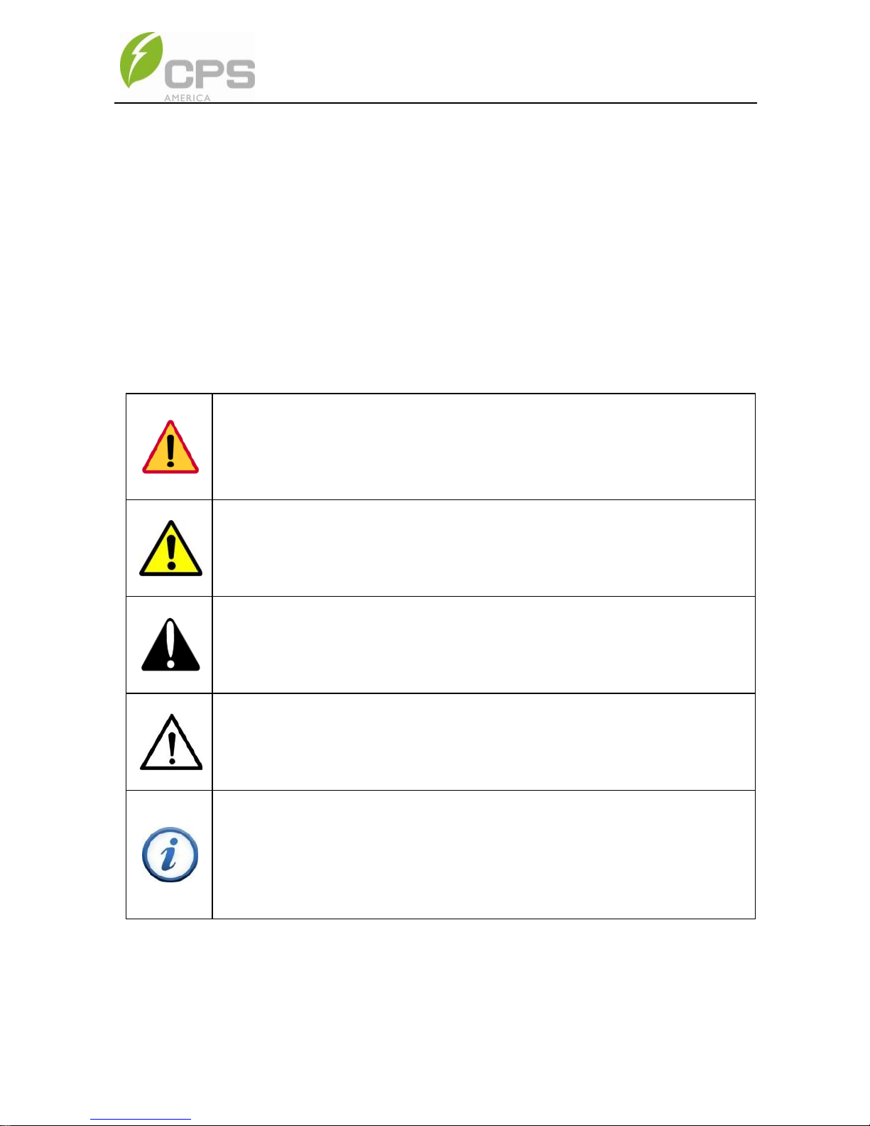
Warnings and symbols in this document
DANGER:
DANGER indicates a hazardous situation which, if not avoided, will
result in death or serious injury.
WARNING:
WARNING indicates a hazardous situation which, if not avoided,
could result in death or serious injury.
CAUTION:
CAUTION indicates a hazardous situation which, if not avoided,
could result in minor or moderate injury.
NOTICE:
NOTICE indicates a hazardous situation which, if not avoided, could
result in the inverter working abnormally or property loss.
INSTRUCTION:
INSTRUCTION indicates important supplementary information or
provides skills or tips that can be used to help you solve a problem or
save you time.
4
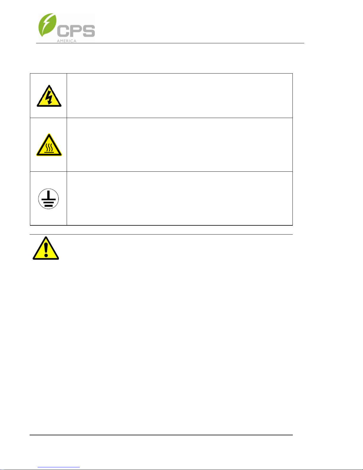
Markings on the product
HIGH VOLTAGE:
This inverter operates with high voltages. All work on the inverter
must only be performed as described in this document.
HOT SURFACE:
The inverter is designed to meet international safety standards, but
surfaces can become hot during operation. Do not touch the heat
sink or peripheral surfaces during or shortly after operation.
EARTH GROUND:
This symbol marks the location of the grounding terminal, which
must be securely connected to Ground through the AC EGC
(Equipment Grounding Conductor) to ensure operational safety.
WARNING:
All the installation and wiring connections must be performed by
qualified technical personnel. Disconnect the inverter from the PV
modules and the AC grid before maintaining or servicing the
equipment.
Risk of electric shock and fire. Use only with PV modules that have
a maximum system voltage of rating of 1000VDC or higher.
Electric shock Hazard. The DC conductors of this photovoltaic
system are normally ungrounded but will become intermittently
grounded without indication when the inverter performs the PV array
isolation measurement.
Shock Hazard. The inverter is energized from both AC and DC
sources. Disconnect all energy sources before servicing.
For continued protection against risk of fire, replace only with same
type and ratings of fuse.
5
DANGER:
Disconnect the inverter from the AC grid and PV modules before
removing covers or opening the equipment. Wait at least 5 minutes
after disconnecting from the DC and AC sources before servicing or
maintaining the inverter. Ensure hazardous high voltage and energy
inside the inverter has been discharged prior to servicing.
NOTICE:
The inverters are designed to only interconnect with an AC power
source as part of the public electric utility grid. Do not connect the AC
output of the inverters directly to any private electric utility power
equipment. The inverters are to be installed with floating or
ungrounded PV arrays only.
CAUTION:
CPS SCA50KTL-DO/US-480 and SCA60KTL-DO/US-480 inverters
weigh approximately 56kg (123.5 pounds). The wirebox portion
weighs approximately 15kg (33 pounds).
Ensure the mounting bracket is properly installed before hanging the
inverter and wirebox on the bracket. A team of two is recommended to
lift and place the inverter and wirebox into position.
INSTRUCTION:
Please check with your local electric utility supply company before
selecting a grid standard. If the inverter is operated with an incorrect
grid standard, the electric utility supply company may cancel the
interconnection agreement.
Placing the inverter into operation before the overall system complies
with the national codes, rules and safety regulations of the application
is also not permitted.
6
2. Overview
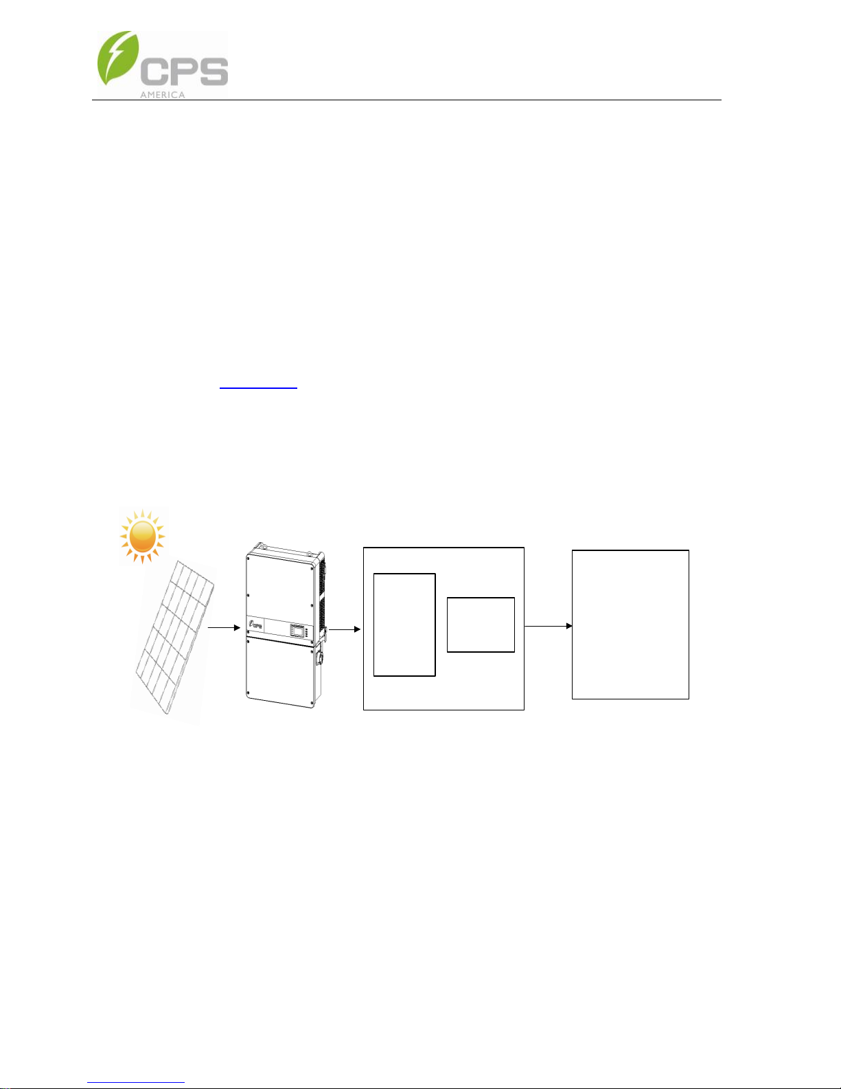
2.1. Inverter for grid-tied PV systems
CPS SCA50KTL-DO/US-480 and SCA60KTL-DO/US-480 3-Phase
Transformerless String Inverters are designed for use with an ungrounded
array in carport, commercial rooftop, and large utility scale PV grid-tied
systems. The system is generally made up of PV modules, a 3-Phase String
Inverter with a fused combiner/disconnect, and AC power distribution
equipment (Figure 2-1). The inverter converts the available DC energy from
the PV modules to AC power by synchronizing the output current to the same
frequency and phase as the AC grid. All or part of the AC power is supplied to
local loads, and the surplus power is exported to the electric utility grid.
AC Grid
Bidirectional
electric meter
AC power
distribution
equipment
Figure 2-1 Grid-tied PV system

7
2.2. Product Features
High conversion efficiency: Advanced 3-level conversion topology with
Space-Vector PWM; Max. efficiency: 98.8%, CEC efficiency: 98.5%.
Grid adaptability: IEEE 1547 Interconnect Standard and CPUC Rule 21
applicable; Reactive Power; >0.99 PF (±0.8 adjustable), Full Active Power
rating to +/-0.91 PF, and optional local or remote Active Power Curtailment.
Flexible communication: Supports standard CPS Modbus RS485, SunSpec
Modbus, and HTTPS/XML communications to ensure compatibility with 3rd
party monitoring and control systems. Flex Gateway enables further
command/control as well as remote firmware upgrades.
Wide DC input voltage range: Operating DC Input Voltage Range:
200-950VDC; Max DC input voltage: 1000VDC.
Long Service Life: Designed with thin-film capacitors to extend inverter's
service life.
3 MPPTs: Multi-channel MPPT (Maximum Power Point Tracker) enable
maximum design flexibility and energy harvest optimization over the life of the
system.
Separable Wirebox: The wirebox enables fused input of either discrete wiring
using the Standard wirebox, or an optional H4 wirebox with quick-fit connectors
for connection of industry standard conductor assemblies.
High protection degree: Powder coated aluminum NEMA 4X enclosure
meets the demanding needs of both indoor and outdoor use.
Intelligent Integration: Integrated load break rated DC/AC disconnect
switches, and up to 15 fused string inputs eliminate the need for external DC
combiner boxes, simplifying installation and the need for DC BOS equipment.

8
2.3. Product Protection Functions
Reverse polarity protection of DC input
AC and DC Short circuit protection
Arc-fault detection and circuit interruption
Anti-islanding detection with bi-directional frequency perturbation
DC Input and AC output over-voltage protection
DC Input over-current protection
DC input insulation against ground monitoring
DC injection of AC output
AC output voltage and frequency monitoring
Leakage current against ground monitoring
Internal enclosure temperature monitoring
IGBT power module temperature monitoring
9
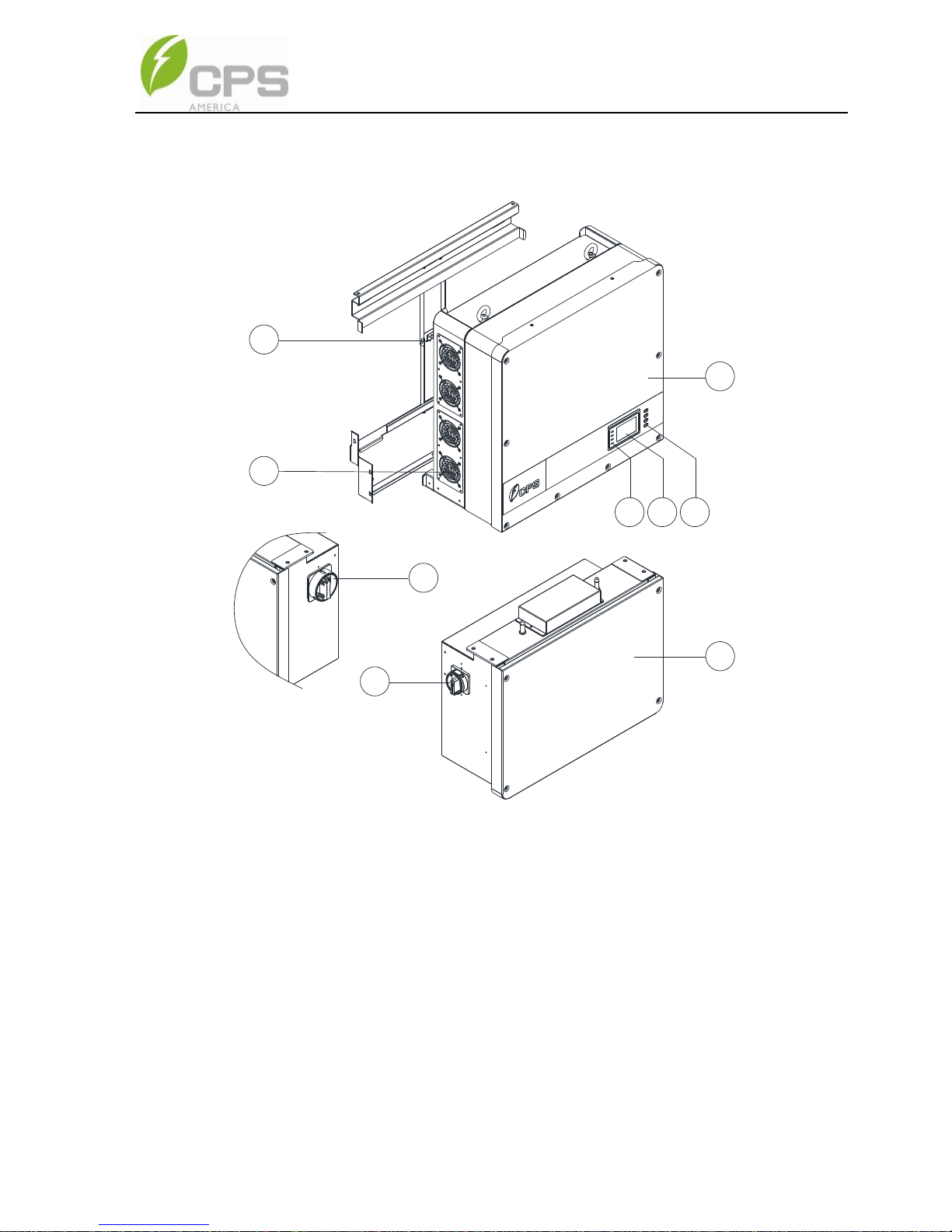
2.4. Appearance and Main Item Description
2
8
9
5 6 7
1
3
4
Figure 2-3 Diagram of the Inverter assembly
Main items of the Inverter:
① Main inverter enclosure
② Inverter wirebox
③ Inverter mounting bracket
④ Cooling fans
⑤ LED indicator lights
⑥ User LCD display
⑦ User Key buttons
⑧ DC switch: DC power on/off
⑨ AC switch: AC power on/off
10
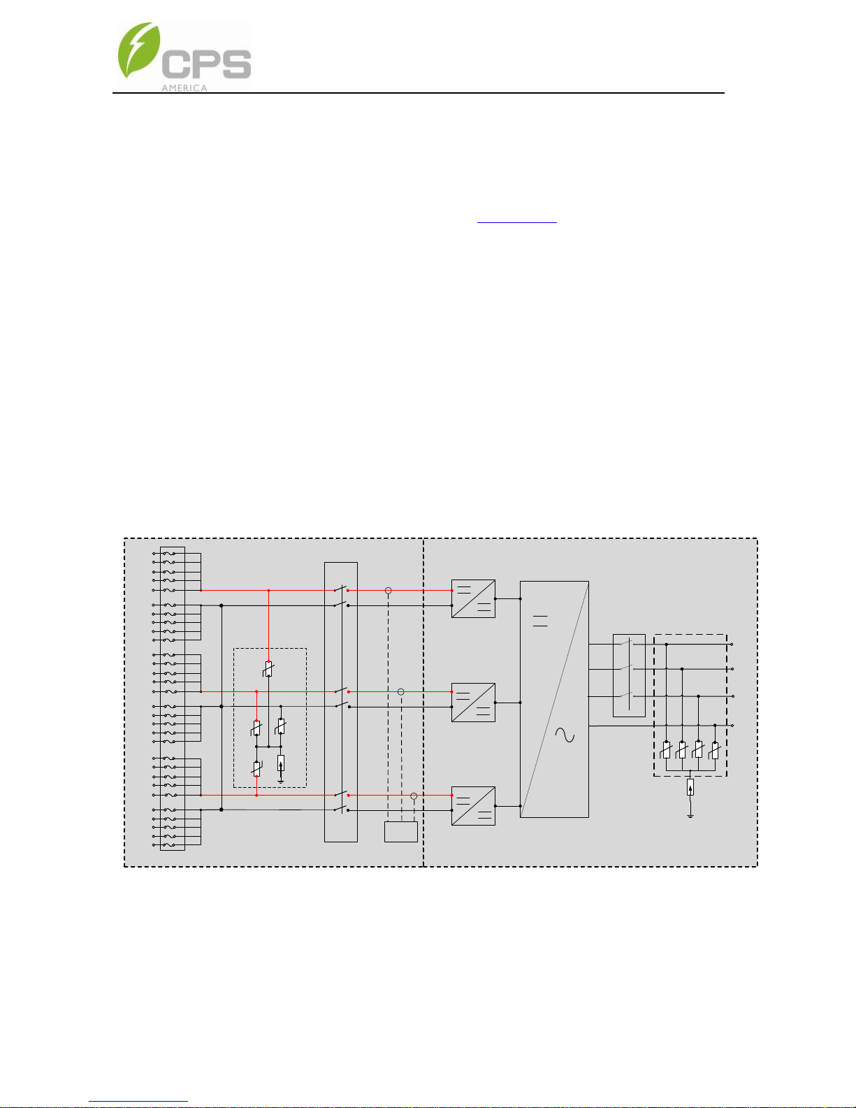
2.5. Schematic Diagram and Circuit Design
The basic electrical schematic diagram of CPS SCA50KTL-DO/US-480 and
SCA60KTL-DO/US-480 inverters are shown in Figure 2-2. The input from PV
source circuits passes through surge protection circuitry, DC EMI wave filters,
and independent DC-DC boost circuitry to achieve maximum power point
tracking and boost the voltages to a common DC bus. The inverter uses line
voltage and frequency measurements to synchronize to the grid and converts
the available PV energy to AC power by injecting balanced 3-phase AC current
into the electric utility grid. Any high frequency AC component is removed by
passing through a two-stage relay and EMI wave filter to produce high quality
AC power.
WIRE BOX INVERTER POWER HEAD
L1
L2
L3
N
PV1+
PV1+
PV1+
PV1+
PV1+
PV1-
PV1PV1-
PV1-
PV1-
MPPT1
MPPT2
AC
Output
PV Input
PV2+
PV2+
PV2+
PV2+
PV2+
PV2-
PV2-
PV2-
PV2PV2-
AC
Switch
Fuses
MPPT3
PV3+
PV3+
PV3+
PV3+
PV3+
PV3PV3-
PV3-
PV3-
PV3-
DC SPD
PV1+
DC Switch
Three
level
inverter
AFD
PV2+
PV3+
PV-
PE
AC SPD
Figure 2-2 Schematic Diagram of the CPS SCA50/60KTL-DO/US-480 Inverter
11
2.6. Anti-islanding Detection
The SCA50KTL-DO/US-480 and SCA60KTL-DO/US-480 inverters include
Unintentional Islanding detection as required by UL 1741/IEEE 1547. The
inverter will continuously make bi-directional perturbations to the frequency of
the output current by injecting a small amount of reactive power to detect a
possible islanding condition. If the grid is stable, these small perturbations will
have negligible effects on the system voltage frequency. However, in an
islanded condition the changes in reactive power will force the frequency of the
system voltage to deviate significantly, which will trigger the inverter to cease
operation and disconnect from the grid.
2.7. DC Ground Fault Protection
The inverters include residual current detection GFCI as part of the DC ground
fault detection method required by UL 1741. If there is a ground fault in the PV
array, the ground fault detection circuitry will detect leakage current, trigger an
alarm, and the inverter will cease operation. See Chapter 5 for further
information regarding GFCI Static and Dynamic trip thresholds and operation.
2.8. Surge Suppression
Standard Waveform Peak Values
Surge Category
Ring Wave
Combination Wave
B
6kV/0.5kA
6kV/3kA
"Standard 1.2/50 μs - 8/20 us Combination Wave"
"Standard 0.5 μs - 100 kHz Ring Wave"
2.9. DC Arc-fault Protection
The inverters include DC Arc-fault detection compliant with UL 1699B. The
inverter will detect electrical noise that is indicative of a DC series arc. Upon
detection of an arc-fault, the inverter will cease operation.
12
3. Installation
This chapter describes the planning and installation procedures for the
SCA50KTL-DO/US-480 and SCA 60KTL-DO/US-480 inverters. Please read
carefully and install the products following the step-by-step instructions.
The inverter and other main items are shipped in two separate packages,
consisting of A.) the main inverter enclosure and B.) the wirebox, mounting
bracket, user manual, and accessory kit. Before installation, please check that
the following items are included in the packages:
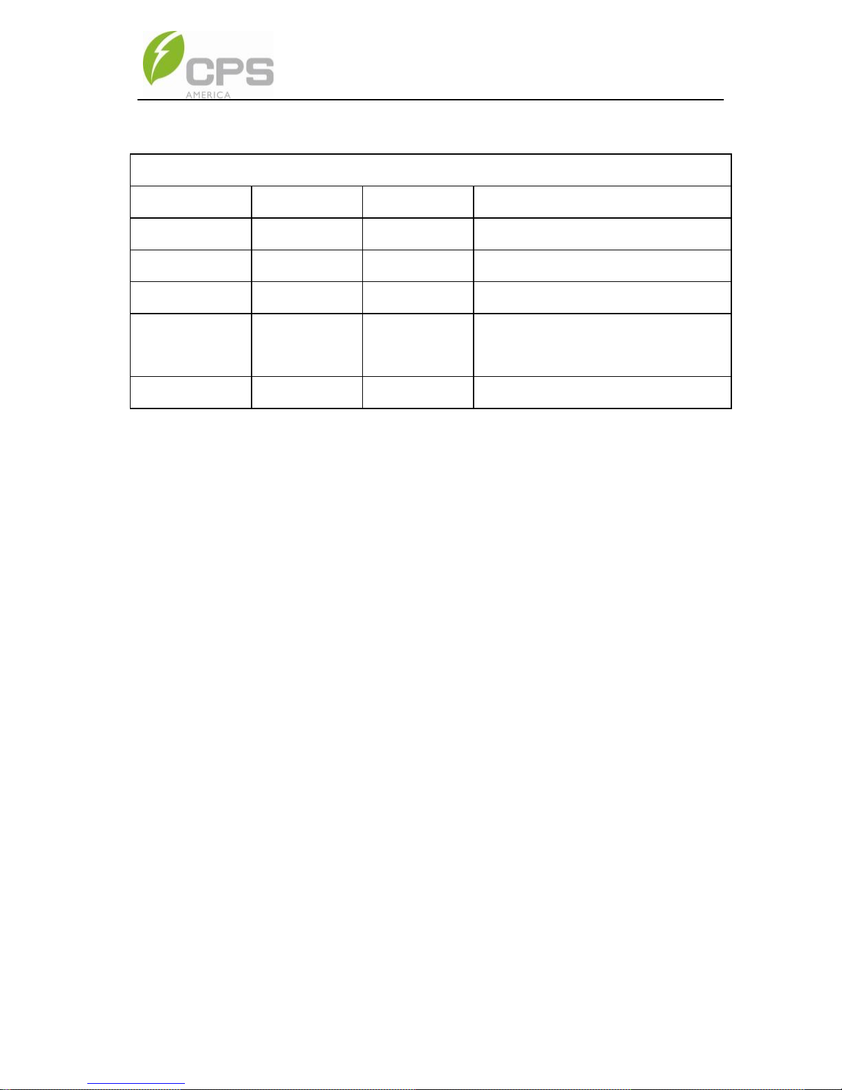
Table 3-1 Main Items
No.
Item
Q’ty
Note
Box
(1)
Main enclosure of
the PV inverter
1 A
(2)
Wiring box of the
PV inverter
1 B
(3)
Mounting bracket
1
Bracket upon which the PV inverter
is hung and mounted
B
(4)
User manual
1
PV inverter installation and
operation manual
B
(5)
Accessory kit
1
Kit contains all necessary hardware
and accessories for installation
B
13
Note that the items in the Accessory Kits vary between the Standard wirebox
and H4 wirebox, the items listed below:
Table 3-2 Accessory Kit (Standard wirebox)
No.
Item
Q’ty
Note
(1)
M8 Expansion Anchors
8
For attaching the mounting bracket to
a concrete wall or surface
(2)
M8×25mm machine
bolts with integrated
lock washer
8
Used with M8 expansion anchors
(3)
M6 X18mm Phillips
screw
11
4 for securing the wiring box to the
main enclosure; 6 for securing the
inverter to the mounting bracket; 1 for
the External Ground connection
(4)
5 pin PCB connector
plug
1
For the RS485 communication
(5)
#10 AWG Wire ferrules*
33
30 for PV conductors, includes 3
spares
(6)
M8 Nut
4
For the AC terminal block
(7)
M8 Flat washer
4
For the AC terminal block
(8)
M8 Spring washer
4
For the AC terminal block
*Wire ferrules included in the accessories are not mandatory for installation.
14
Table 3-3 Accessory Kit (H4 wirebox)
No.
Item
Q’ty
Note
(1)
M8 Expansion Anchors
8
For attaching the mounting bracket to
concrete wall or surface
(2)
M8×25mm machine
bolts with integrated
lock washer
8
Used with M8 expansion anchors
(3)
M6 X18mm Phillips
screw
11
4 for securing the wiring box to the
main enclosure; 6 for securing the
inverter to the mounting bracket; 1 for
the External Ground connection
(4)
5 pin PCB connector
plug
1
For the RS485 communication
(5)
PV Connector (Male)
15
For the PV input. #14 AWG contact
(6)
PV Connector (Female)
15
For the PV input. #14 AWG contact
(7)
Tool for PV Connector
1
For assembling/disconnecting PV
Connector
(8)
M8 Nut
4
For the AC terminal block
(9)
M8 Flat washer
4
For the AC terminal block
(10)
M8 Spring washer
4
For the AC terminal block
INSTRUCTION:
The items in the Accessory Kit Table 3-2 and Table 3-3 above are for
the standard configuration. The accessories provided may vary if
optional parts are purchased.
15
3.1. Recommendations before Installation
See Chapter 10, Technical Data for specification ranges and limits.
Check that the inverter environmental specifications (protection degree,
operating temperature range, humidity and altitude, etc) meet the
requirements of the specific project location.
Make sure that the electric utility grid voltage is within range for the grid
standard chosen.
Ensure that the local electric utility grid authority has granted permission
to connect to the grid.
Installation personnel must be qualified electricians or those who have
received professional training.
Wear and use proper PPE (personal protective equipment) during
installation.
Sufficient space according to Figure 3-3 and Figure 3-4 must be
provided to allow the inverter cooling system to operate effectively.
Install the inverter away from flammable and/or combustible substances.
Avoid installing the inverter in locations that exceed the temperature
limits specified for the inverter to prevent undesirable power loss.
Do not install the inverter near an electromagnetic source which can
compromise the normal operation of electronic equipment.
NOTICE:
The allowable ambient temperature range for the
SCA50KTL-DO/US-480 and SCA 60KTL-DO/US-480 inverters is
defined based on the following conditions;
Condition 1: -40°C to 70°C, Inverter not installed, and in storage (in
packaging or unpackaged).
Condition 2: -30°C to 60°C, Inverter installed, connected to electric
utility grid and operating during daylight hours.
Condition 3: No low temp limit to 70°C, Inverter installed, connected to
electric utility grid but non-operating (daylight or nighttime hours).

16
NOTICE:
Outdoor Installations for Extended Periods without Power
CPS advises against leaving inverters mounted outdoors for an
extended period of time (more than 90 days) and/or allowing inverters
exposed to cycles of freezing temperature without both DC and AC
power connected to the inverters under normal operation.
The CPS inverter enclosures are designed to conform to NEMA4 (or
IP65), however there exists the possibility of water condensation inside
the inverter enclosure when it is left exposed to an outdoor environment
without power to operate for an extended period of time. Moisture in the
air could enter the power head of the inverter through the small opening
between wiring box and power head during the time that the wiring box
cover is opened for wiring purposes. When the inverter is exposed to
temperature swings, especially in cold weather, moisture inside the
inverter power head could condense over the aluminum heatsink area
where inverter semiconductors are mounted. Water droplets on the
heatsink may cause a short-circuit to live semiconductor devices. When
the PV source is applied to the inverter, this PV power source could
cause the inverter to fail and result in a short-circuit across the PV
array.
If such a situation in which the inverter is mounted outdoors without
operating power occurs, CPS recommends that the inverter power
head be inspected for water condensation before any DC or AC power
can be applied to inverter. Without inspection, customers will run the
risk of having inverter electronic circuit damage when power is applied
to inverter during startup. It is advised that customers contact CPS for
further advice and to arrange schedule for CPS service personnel to
perform inspection of inverter on site.
- CPS hotline: 855-584-7168
17
3.2. Mechanical Installation
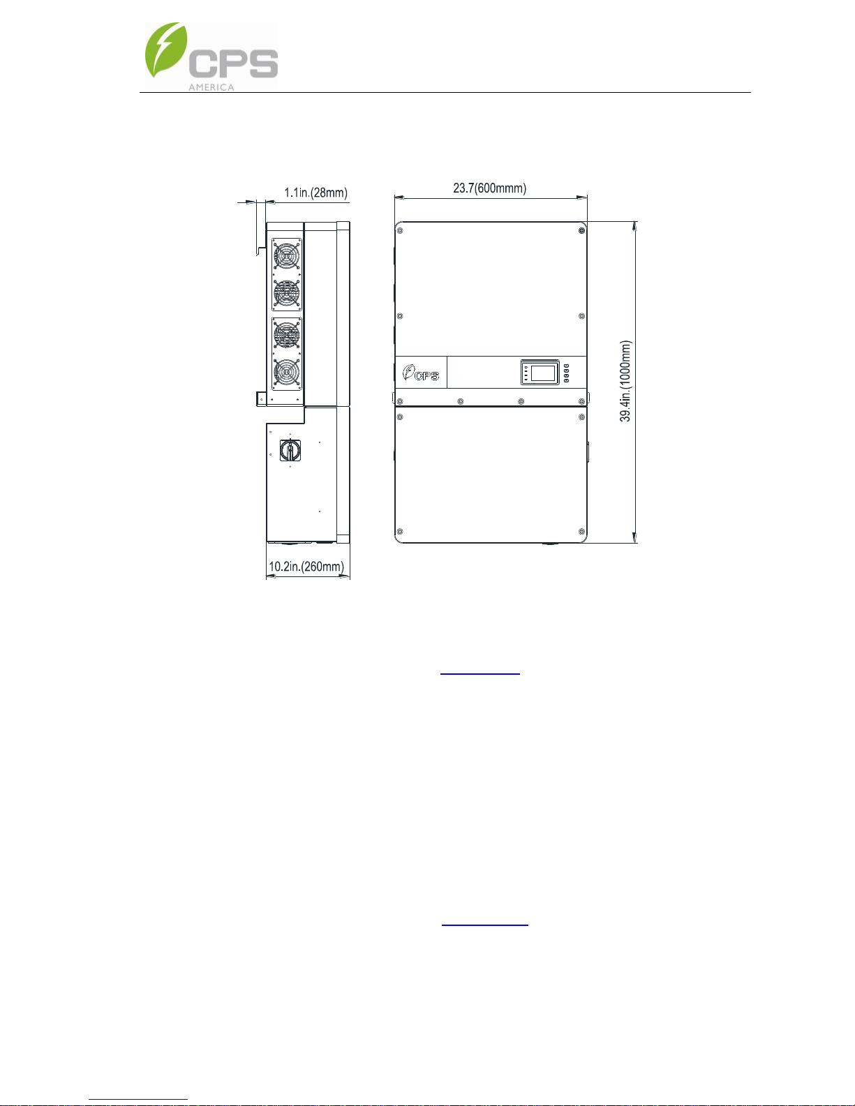
3.2.1. Dimensions
Figure 3-1 Dimensions of the Inverter
3.2.2. Installation Method (see Figure 3-2):
Ensure that the mounting structure (wall, rack, roof, etc) is suitable to
support the weight of the inverter. Follow the mounting guidelines below:
(a) If the location permits, install the inverter vertically.
(b) If the inverter cannot be mounted vertically, it may be tilted backward
at any angle from vertical to horizontal.
(c) When tilted backward at ≤75° from horizontal in an outdoor
environment, the CPS Shade Cover (SSC-60ST) accessory is
required to be installed. See Section 9.2 for more information.
(d) Do not mount the inverter leaning forward.
(e) Do not mount the inverter upside down.
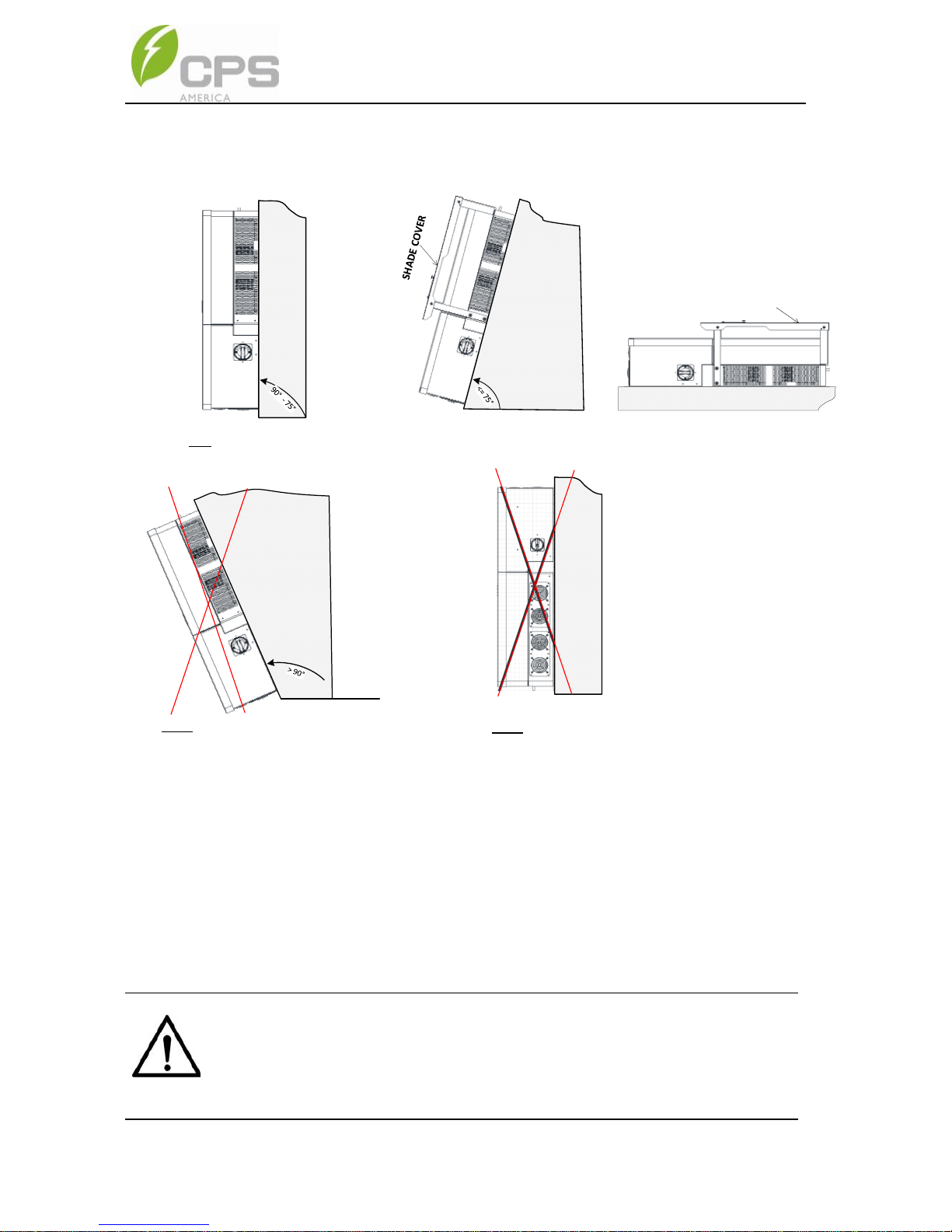
18
a.) NO SHADE COVER REQUIRED
SHADE COVER
b.) SHADE COVER REQUIRED
c.) NOT > 90° TILTED FORWARD
d.) NOT UPSIDE DOWN
Figure 3-2 Inverter Mounting Options
NOTICE:
When the inverter is mounted tilted backward at ≤75° from horizontal
in an outdoor environment, the CPS Shade Cover (SSC-60ST)
accessory must be installed on the inverter to avoid direct sunlight.

19
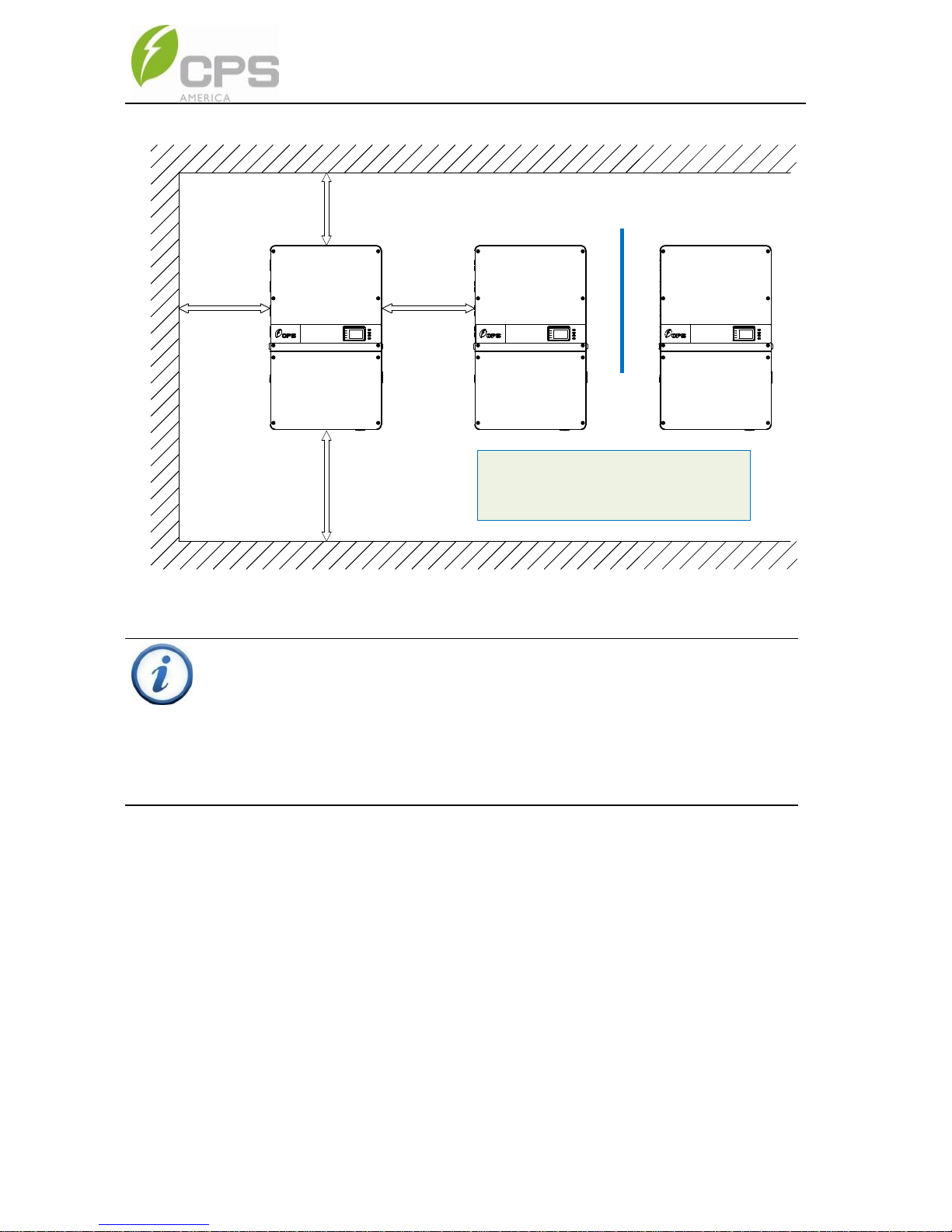
3.2.3. Installation Space Requirement
The distances between the inverters or the surrounding objects should
meet the following conditions:
≥300mm
(11.8in.)
≥300mm
(11.8in.)
≥500mm
(19.7in.)
=600mm
(23.6in.)
Note:This dimension can be modified
according to installation requirements.
NOTICE:
The spacing between two adjacently mounted inverters must be
≥19.7in (500mm). Spacing should be enlarged for installation
locations with ambient temperature higher than 45°C. Ensure that the
air space around the inverter is well ventilated. The spacing below the
inverter is intended to ensure the LCD and Keypad height are well
positioned for the user, and may be decreased, however
consideration must be taken for locations known to flood or have
seasonal snow build up.
20
300mm
(11.8in.)
300mm
(11.8in.)
500mm
(19.7in.)
=600mm
(23.6in.)
BAFFLE
BAFFLE MUST:
1. EXTEND MIN. ABOVE AND BELOW FANS
2. EXTEND 4" MIN. PAST FRONT OF INVERTER
3. LOCATED 8" MIN. FROM BOTH INVERTERS
Figure 3-3 Inverter Wall Mounting Dimensions
INSTRUCTION:
If the inverter is installed on Unistrut or the array racking (instead of
solid wall), the space from the bottom of one inverter to the top of the
inverter below may be as small as 3.9in (100mm). The spacing below
may be as small as 11.8in (300mm).
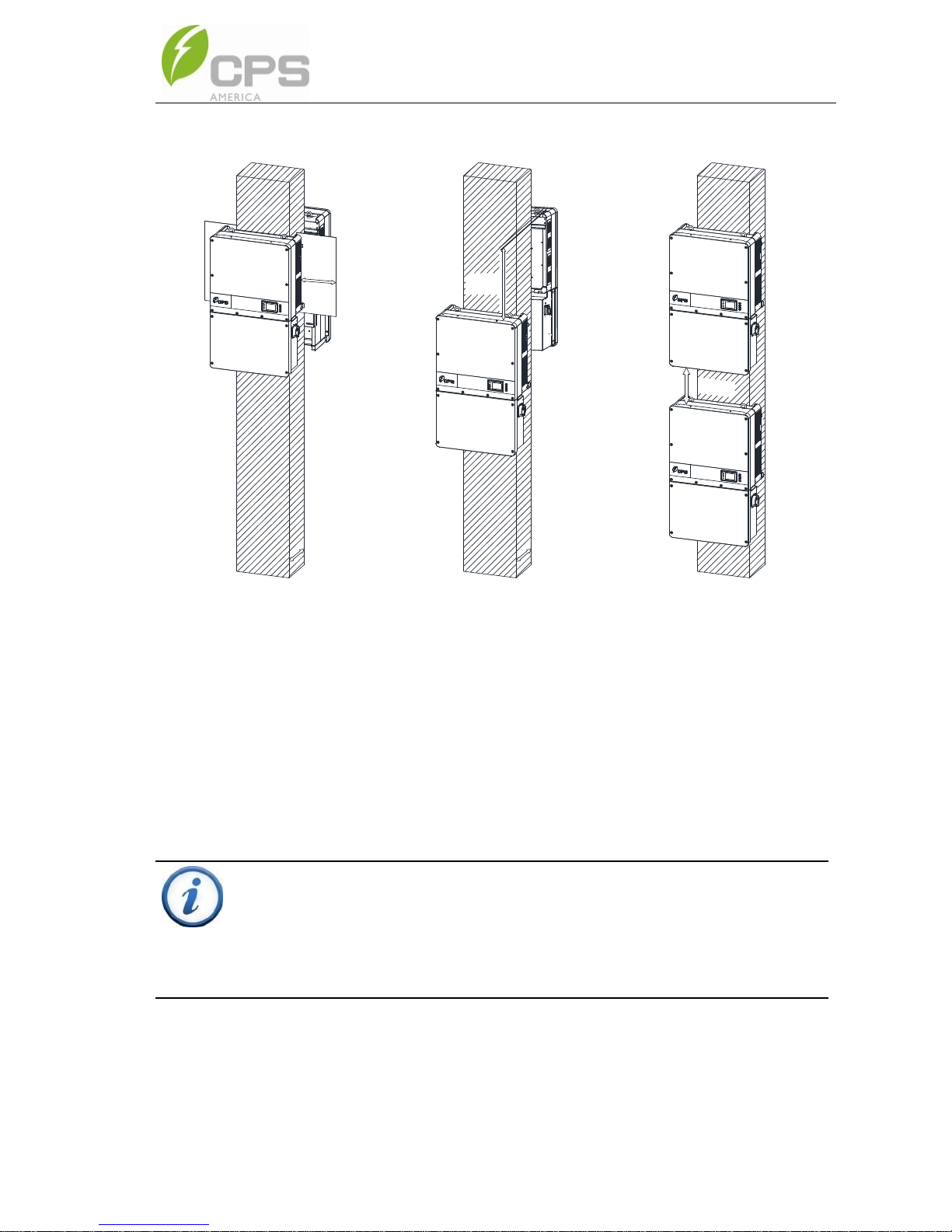
21
8in.
24in.
12in.
12in.
12in.
Figure 3-4 Inverter Pillar or Column Mounting Dimensions
INSTRUCTION:
If the inverter is installed on a pillar or column (instead of solid wall),
the space from the bottom of one inverter to the top of the inverter
below may be as small as 12in (300mm).
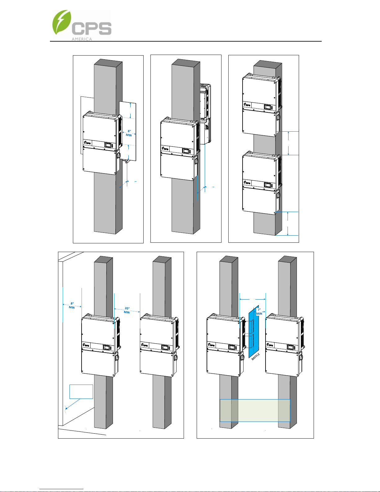
22
8"
MIN
8"
MIN
12"
MIN
BAFFLE
BAFFLE
12"
MIN
12"
MIN
12"
MIN
A)
B)
C)
D)
E)
14"
MIN
BAFFLE MUS T:
1. EXTEND MIN. ABOVE AND BE LOW FANS
2. EXTEND 4" MIN. PAST FRONT OF INVE RTER
3. LOCATED 7" MIN. FROM BOTH IN VERTERS
WALL OR
PASSIVE
CABINET
23
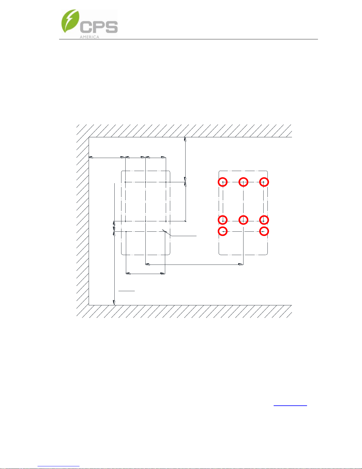
3.2.4. Mounting the Inverter onto the Bracket
1. Locate and mark the 8 holes on the wall, PV racking structure, or
bearing surface for attaching the inverter mounting bracket as shown
in Figure 3-5.
=874mm(34.4in.)
≥435mm
250mm
≥350mm
465mm
125mm(4.9in.)
≥1100mm(min.)
(13.8in.)
(9.84in.)
250mm
(9.84in.)
(17.1in.)
(43.3in)
(18.3in.)
8-? 10.0
480~500mm
(18.9~19.7in)
Note:This dimension can be modified
according to installation requirements.
Figure 3-5 Dimensions of the bracket anchoring holes for mounting
a. PV Racking Mount: Locate holes or anchors at the marked
positions; Fasten the Mounting Bracket ② with the M8x25
Assembling Bolts ③ supplied with the Accessory Kit. M8
nuts are not provided in the Accessory Kit. See Figure 3-7.
Tools Required: No. 13 wrench(es)
24
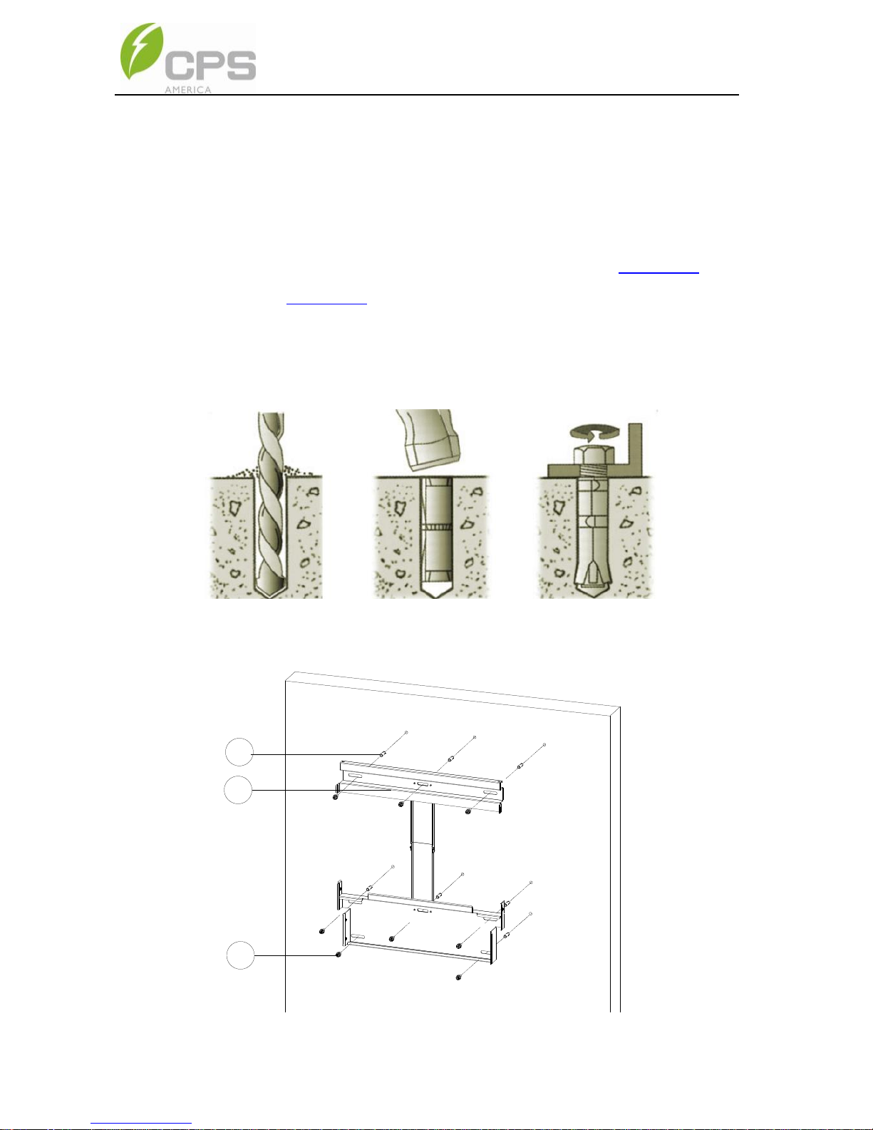
b. Concrete Wall Mount: Drill holes at the marked positions
with a 0.4in. (10mm) masonry bit and insert the M8
Expansion Anchors ① into the holes; Fasten the
Mounting Bracket ② with the M8x25 Assembling
Bolts ③ supplied with the Accessory Kit. Figure 3-6 and
Figure 3-7.
Tools Required: Electric drill (Ф10mm/0.4in. masonry bit),
No. 13 wrench
Figure 3-6 Drill holes, set Anchors, and tighten Assembling Bolts
1
2
3
Figure 3-7 Secure the Mounting Bracket
 Loading...