

CPS SCA3KTL-O/US, CPS SCA4KTL-O/US, CPS SCA5KTL-O/US Installation And Operation Manual
CPS SCA Series Grid-Tied PV-Inverter
CPS SCA3/4/5KTL-O/US
Installation and Operation Manual
Version 1.0

Table of Contents
Before You Start… ...............................................................................................1
Chapter 1 IMPORTANT Safety Instructions .......................................................2
Chapter 2 Overview .............................................................................................5
2.1 Inverter for grid-tied PV systems.................................................................5
2.2 Product features .........................................................................................6
2.3 Dimensions of Inverters ..............................................................................7
2.4 Appearance description ..............................................................................8
Chapter 3 Installation ........................................................................................ 11
3.1 Inside the Package ................................................................................... 11
3.2 Basic requirements ................................................................................... 12
3.3 Mounting the PV-Inverter .......................................................................... 13
3.4 Electrical installation ................................................................................. 18
3.4.1 DC Connection.................................................................................. 18
3.4.2 AC Connection .................................................................................. 23
3.4.3 Wiring Checklist ................................................................................ 24
3.4.4 Communication Interface .................................................................. 25
3.4.4.1 Standard RS-485 Communication ............................................. 25
3.4.4.2 Optional Ethernet Communication ............................................ 26
Chapter 4 Commissioning ................................................................................ 27
4.1 Start Up .................................................................................................... 27
4.2 First-Time Start Up ................................................................................... 27
4.3 Start Up Sequence ................................................................................... 31
Chapter 5 User Interface ................................................................................... 33
5.1 Normal Operation and Display Menu ........................................................ 33
5.1.1 Status Screens.................................................................................. 33
5.1.2 LED Lights ........................................................................................ 35
5.1.3 Inverter Information and Settings ...................................................... 35
5.1.4 Inverter Information ................................................................ ........... 36
5.1.5 Inverter Settings ................................................................................ 37
5.1.6 Display Messages ............................................................................. 39
Chapter 6 Preventative Maintenance ............................................................... 41
6.1 Troubleshooting ........................................................................................ 41
6.2 Checking and maintenance ...................................................................... 43
Chapter 7 Technical Data .................................................................................. 44
Chapter 8 Limited Warranty .............................................................................. 46
8.1 Disposal .................................................................................................... 46
8.2 Contact Information .................................................................................. 46

1
Before You Start…
This manual contains important information regarding installation and safe
operation of this unit. Be sure to read this manual carefully before using.
Thank you for choosing this CPS Grid-tied PV Inverter. This PV Inverter is a high
performance and highly reliable product specifically designed for the North
American Solar market.
If you encounter any problems during installation or operation of this unit, first
check the user manual before contacting your local dealer or supplier. This user
manual is applicable for the following 3 models: CPS SCA3KTL-O/US, CPS
SCA4KTL-O/US and CPS SCA5KTL-O/US.
Instructions inside this user manual will help you solve most installation and
operation difficulties. Please keep this user manual on hand for quick reference.
2
Chapter 1 IMPORTANT SAFETY INSTRUCTIONS
(SAVE THESE INSTRUCTIONS)
Please read this user manual carefully before undertaking the installation. CPS
reserves the right to refuse warranty claims for equipment damage if the user fails
to install the equipment per the instructions in this manual.
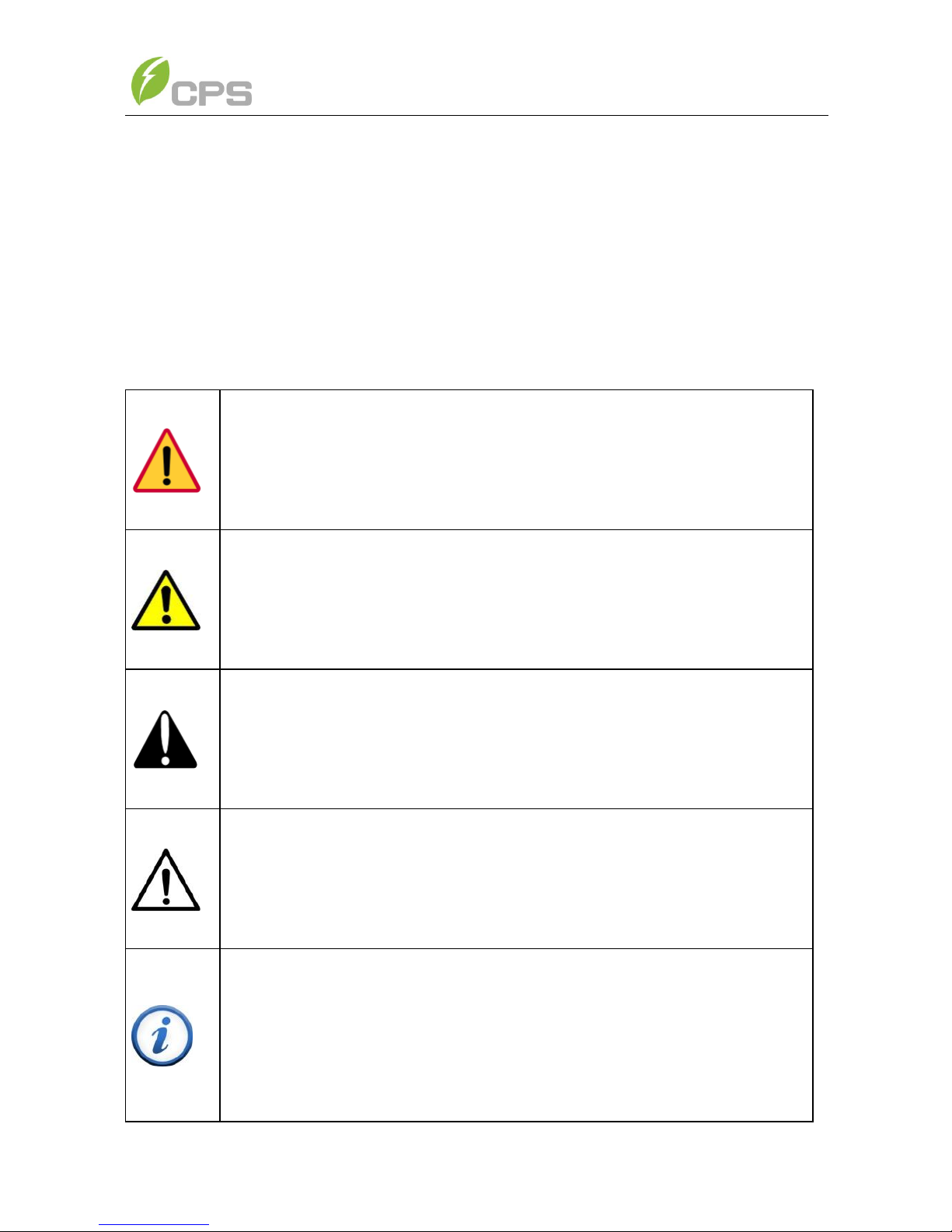
DANGER:
DANGER indicates a hazardous situation which, if not avoided, will
result in death or serious injury.
WARNING:
WARNING indicates a hazardous situation which, if not avoided,
could result in death or serious injury.
CAUTION:
CAUTION indicates a hazardous situation which, if not avoided,
could result in minor or moderate injury.
NOTICE:
NOTICE indicates a hazardous situation which, if not avoided, could
result in equipment working abnormally or property loss.
INSTRUCTION:
INSTRUCTION indicates important supplementary information or
provides skills or tips that can be used to help you solve a problem or
save you time.
3
Warnings and symbols in this document
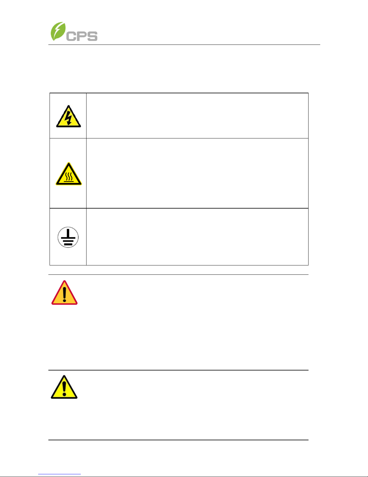
Markings on the product
HIGH VOLTAGE:
The product works with high voltages. All work on the product
must only be performed as described in this document.
HOT SURFACE:
The equipment is designed to meet international safety
standards, but surfaces can become hot during operation. Do
not touch the heat sink or peripheral surfaces during or shortly
after operation.
EARTH GROUND:
This symbol marks the location of grounding terminal, which
must be securely connected to the earth through the PE
(protective earthing) cable to ensure operational safety.
DANGER:
Please disconnect the inverter from AC grid and PV modules before
opening the equipment. When the PV array is exposed to light, it
supplies DC voltage to this equipment. Make sure hazardous high
voltage and energy inside the equipment has been discharged.
Do not operate or maintain the inverter until at least 8 minutes after
disconnecting all sources from DC and AC sides.
WARNING:
All the installation and wiring connections should be performed only
by qualified technical personnel. Disconnect the inverter from PV
modules and the Power Grid before maintaining and operating the
equipment.
4
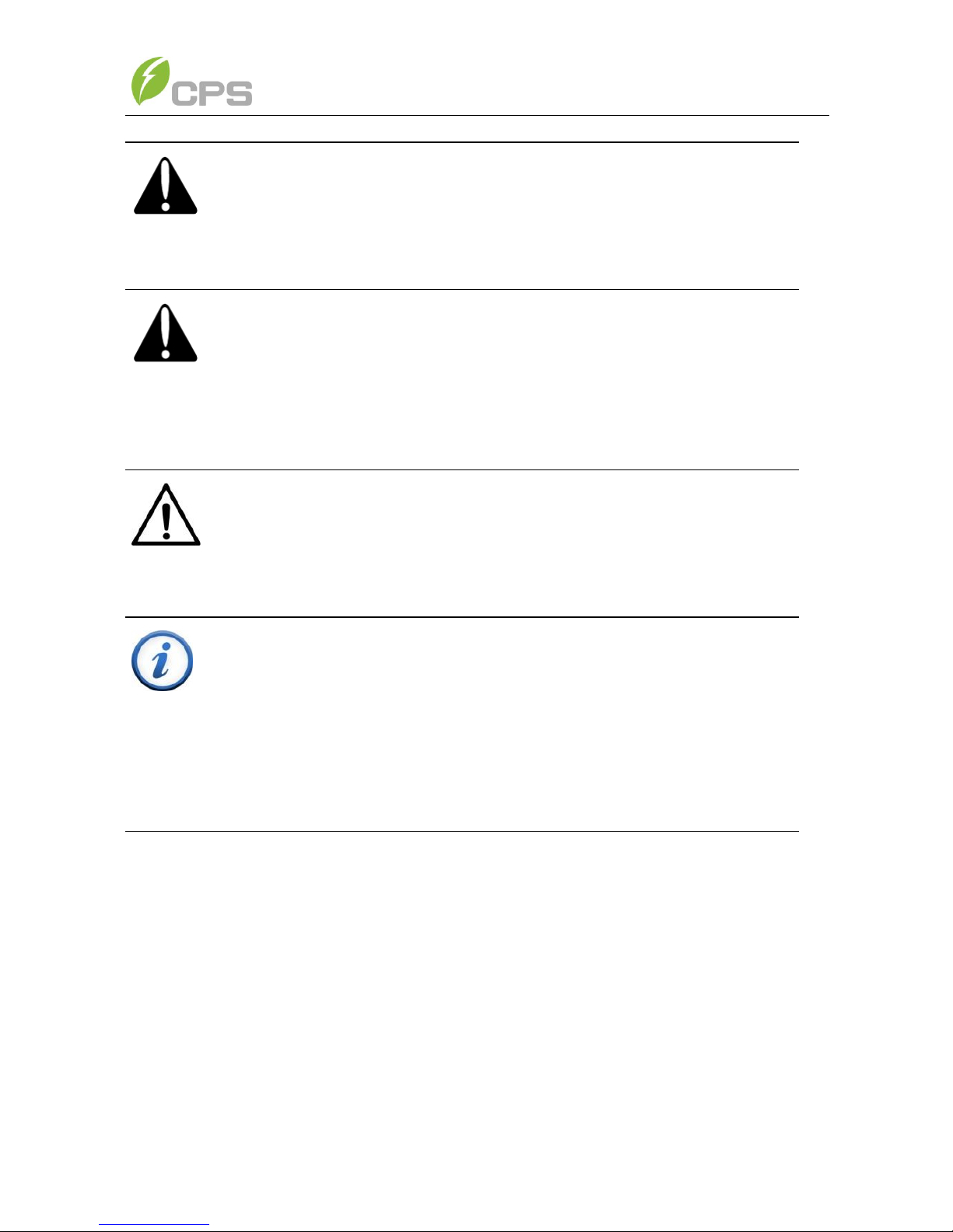
CAUTION:
Although designed to meet international safety standards, the
PV-Inverter can become hot during operation. Do not touch the heat
sink or peripheral surfaces during or shortly after operation.
CAUTION:
CPS SCA3/4/5KTL series inverter is approx 38kg (84lbs).
Please Check the mounting bracket again before the PV Inverter is
hung on to the bracket. At least 2 people are required for this
procedure due to the weight of the inverter.
NOTICE:
This inverter is designed to connect AC power only to the public grid.
Do not connect the AC output of this equipment directly to any
private AC power equipment.
INSTRUCTION:
Please check with your local electricity supply company before
selecting the grid connection standard.
Putting the inverter into operation before the overall system complies
with the national rules and safety regulation of the application is not
permitted.
5
Chapter 2 Overview
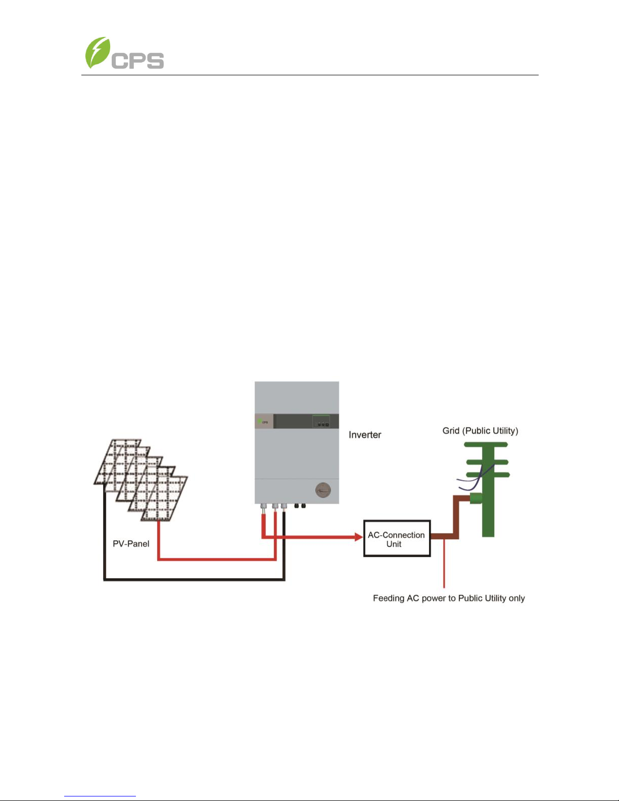
2.1 Inverter for grid-tied PV systems
CPS SCA3/4/5KTL series inverter is suitable for use with most household
grid-tied systems. The system is generally made up of PV-panels, a PV-inverter,
an AC-Connection Unit (the connection Interface) and the Grid (Electric Utility)
(see Figure 2-1). When a PV-panel is exposed to sufficient irradiation (sunlight)
and connected to an inverter, it generates DC power. The PV-Inverter converts DC
power to AC power supplied to the Electric Utility via the AC-Connection unit. The
AC power generated is supplied first to local loads. Any excess power is
supplied to your local Electric Utility.
The following figure shows the PV-Inverter in the grid-tied PV System:
Figure 2-1 Grid-tied PV system

6
2.2 Product features
Lead-free, RoHS compliant
Up to 97.5% peak conversion efficiency
Dual MPPT design
NEMA 3R outdoor rated enclosure
2x16 LCD display
Single phase, 208V L-L or 240V L-L
Compact design
High reliability with a standard 10 year warranty
Easy operation
Maintenance free operation
Remote Communications Interface
Complies with IEEE1547: 2003, IEEE1547.1: 2005 Standards
Integrated GFDI on PV arrays
Integrated series Arc Fault Detection.
7
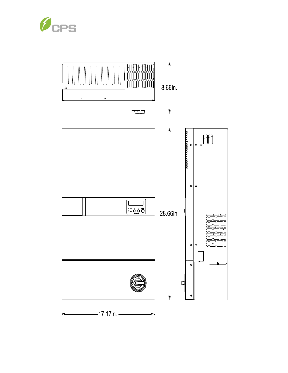
2.3 Dimensions
Figure 2-2 Dimensions of CPS SCA3/4/5K-O/US
8
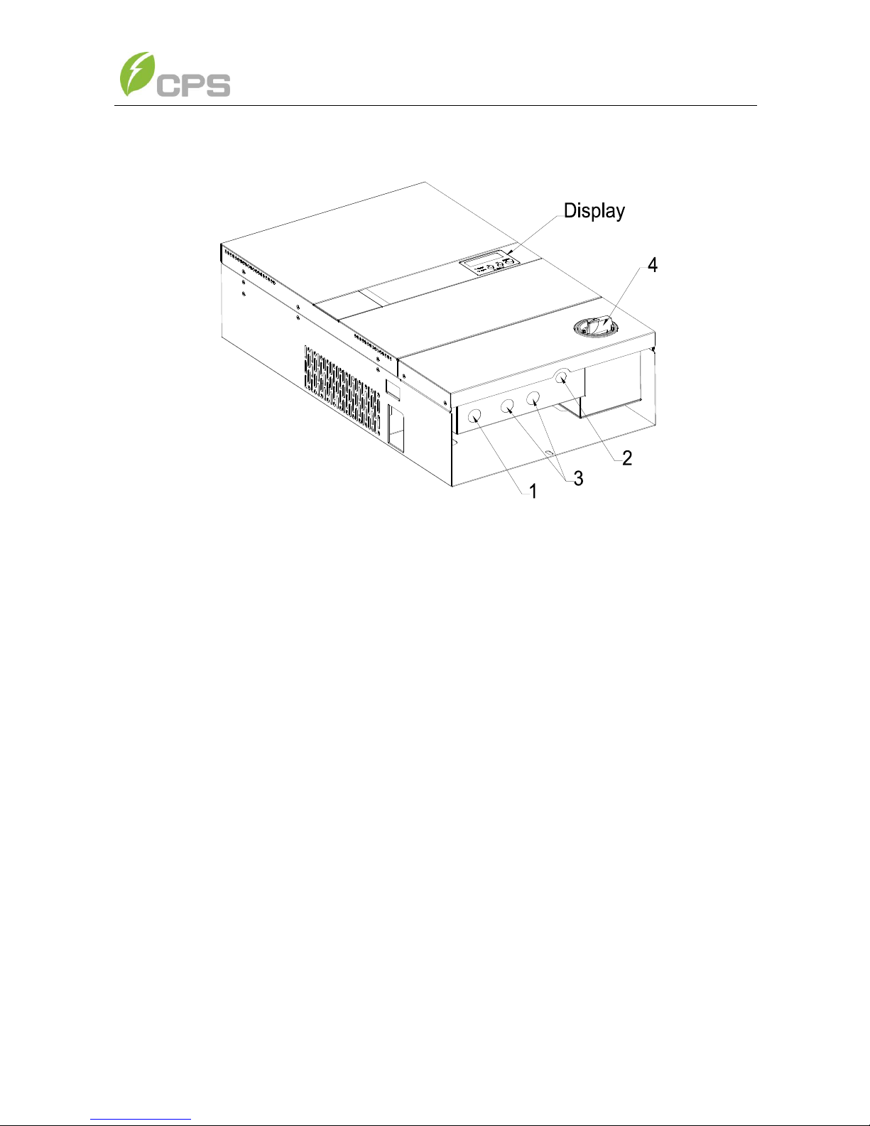
2.4 Exterior Parts Description
Figure 2-3 Exterior Parts Description
(1) AC-Output Cable Knockout: ¾” knockout for cable conduit for Grid
connection L1 (Line 1), L2 (Line 2)/N (Neutral), GND (PE).
(2) Communication Interface Knockout: Use this location for inverter
communications wiring.
(3) PV-Input Knockouts: Two ¾” knockouts for cable conduits for PV arrays
connection. Refer to Installation Section for set-up information.
(4) AC/DC Disconnect Switch: This switch disconnects/connects both Grid and
PV from/to Inverter.
- Horizontal switch position (0): Disconnect
- Vertical switch position (1): Connect
9
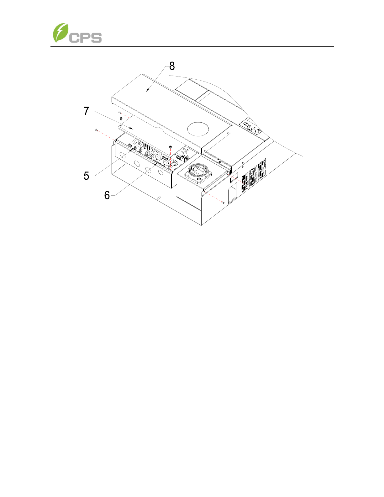
Figure 2-4 Remove the Wiring box terminal cover
(5) and (6) AC/DC Wiring Box and Terminals: AC and DC wiring termination.
(7) Wiring Box Cover: Transparent plastic cover to protect wiring termination
area.
(8) Lower Panel: Weather sealed cover for the wiring box
10
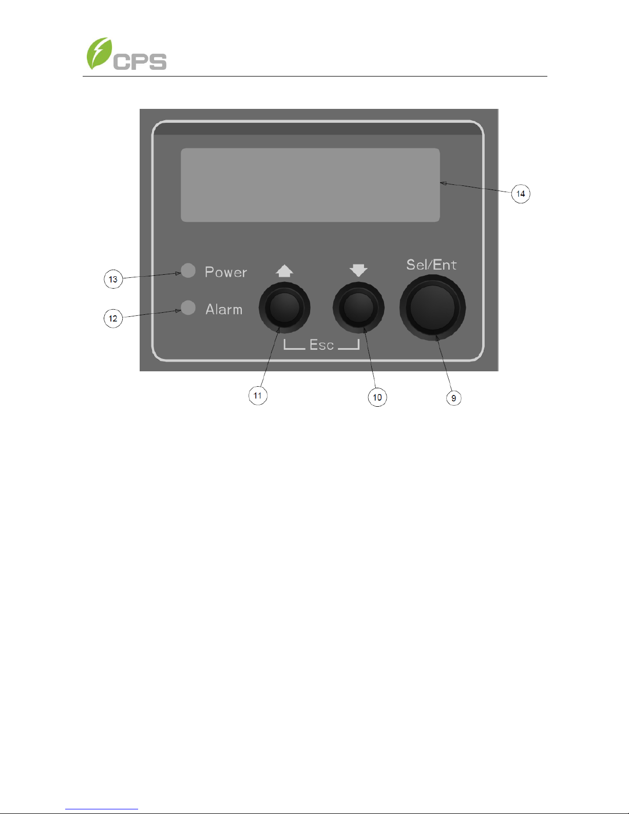
Figure 2-5 LCD panel
(9) Sel/Ent Key: SELECT or ENTER key used to make display menu selections
(10) Down Key: Key used to move down the selection list in the display menu
(11) Up Key: Key used to move up the selection list in the display menu
(12) Alarm Indicator: Red light indicates an alarm that prevents the Inverter from
exporting power to Grid.
(13) Power Indicator: Green light indicates the inverter is operating normally and
exporting power to Grid.
(14) LCD: 16x2 character LCD display for detailed Inverter, PV, and Grid condition
information.
11
Chapter 3 Installation
Please read the following installation instructions carefully and install the product
step-by-step.
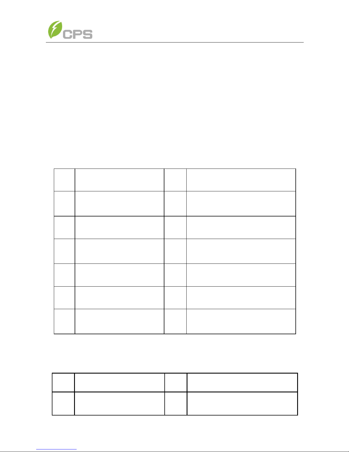
3.1 Inside the Package
The following items are included in the package:
Table 3-1 Main items
No.
Item
Qty
Note
(1)
Grid-tied
PV inverter
1
(2)
Mounting bracket
1
Inverter wall mounting bracket
(3)
Installation and Operation
Manual
1
(4)
Warranty service card
1
For maintenance and repair
(5)
Packing list
1
(6)
Accessory kit
1
Contains all necessary
installation accessories
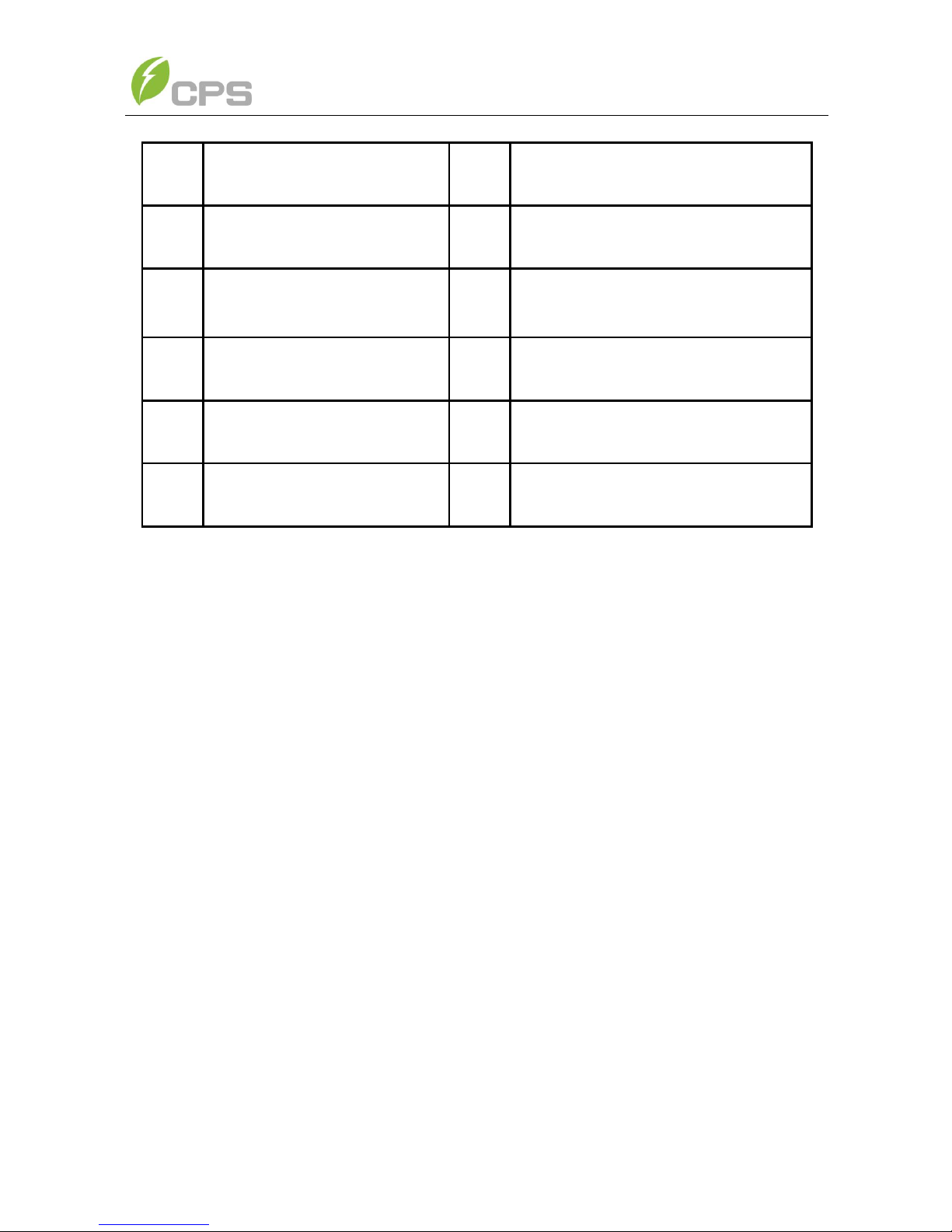
The (6) Accessory kit contains items listed below:
Table 3-2 Accessories
No.
Item
Qty
Remarks
(1)
Mounting Screws
8
For mounting bracket
12
(2)
Snap Bushings/anchors
8
For mounting bracket
(3)
Safety-lock screws
1
To secure the inverter
(4)
Mounting plate of the data
logger
1
For optional comm. card
(5)
Ring terminals
13
For wire connections
(6)
Cable gland
1
For communication ports
(7)
Seal pin
2
For cable gland holes
3.2 Basic requirements
Check that the product environmental specifications (protection degree,
operating temperature range, humidity and altitude) meet the requirements
of the specific project location;
Make sure that the power grid voltage is within normal range;
Ensure that the local electricity supply authority has granted permission to
connect to the grid;
Installation personnel must be qualified electricians or people who have
received professional training;
Sufficient space is provided to allow the inverter cooling system to operate
normally;
Install the inverter away from flammable and explosive substances;
Avoid installing the inverter in locations that exceed the temperature limits
specified in the inverter data sheet to limit undesirable power loss;
Do not install the inverter near an electromagnetic source which can
compromise the normal operation of electronic equipment;

13
3.3 Mounting the PV-Inverter
To mount the inverter to a wall or structure, please follow these steps:
1. Select a wall or solid vertical surface which is strong enough to support
the inverter.
2. The PV-Inverter requires adequate cooling space for heat dissipation.
Reserve at least 300mm (~12”) above and 500mm (~20”) (measured
start from the bottom of the AC cover) below the inverter. Each
inverter should have a minimum of 300mm (~12”) space to each other
for multiple inverters installation.
INSTRUCTION:
The PV-Inverter can operate at locations where the ambient temperature
is up to 60C (140F). However, for optimal power production, it is
recommended that inverter is installed where the ambient temperature is
between -25C and +45C (-13F ~+113F)
 Loading...