

CPS SCA23KTL-DO/US-480, SCA28KTL-DO/US-480 Installation And Operation Manual

1
CPS SCA Series Grid-tied PV Inverter
CPS SCA23/28KTL-DO/US-480
Installation and Operation Manual
Version 1.4
SHANGHAI CHINT POWER SYSTEMS CO., LTD.

2
Table of Contents
Before You Start… ...................................................................................... 4
Chapter 1 IMPORTANT SAFETY INSTRUCTIONS .................................... 5
Chapter 2 Overview .................................................................................... 8
2.1 Inverter for grid-tied PV systems ................................................... 8
2.2 Product features ............................................................................ 8
2.3 Product protection functions ......................................................... 9
2.4 Circuit structure design ................................................................. 9
2.5 Appearance Description ................................................................ 11
Chapter 3 Installation ................................................................................. 12
3.1 Recommendations before installation ........................................... 14
3.2 Mechanical installation .................................................................. 15
3.3 Electrical installation ..................................................................... 28
3.3.1 DC connection ....................................................................... 29
3.3.2 AC and ground connection .................................................... 41
3.3.3 Communication connection ................................................... 47
Chapter 4 Commissioning ......................................................................... 56
4.1 Commissioning Checklist .............................................................. 56
4.1.1 Mechanical installation .......................................................... 56
4.1.2 Cable connections ................................................................. 56
4.1.3 Electrical check ..................................................................... 56
4.2 Commissioning steps .................................................................... 56
Chapter 5 User Interface ............................................................................ 59
5.1 Description of LCD panel .............................................................. 59
5.2 Operation state ............................................................................. 61
5.3 Interface types .............................................................................. 61
5.4 Menu functions.............................................................................. 63
5.4.1 Operation information ............................................................ 64
5.4.2 Alarm ..................................................................................... 65

3
5.4.3 History ................................................................................... 65
5.4.4 System configuration ............................................................. 67
5.4.5 Power dispatch ...................................................................... 70
5.4.6 System protection parameters setup ..................................... 70
5.4.7 System control parameters ................................ .................... 72
5.4.8 Arcing fault current interruption .............................................. 79
Chapter 6 Operation ................................................................................... 82
6.1 Start-up ......................................................................................... 82
6.2 Shut-down ..................................................................................... 82
6.3 Operation mode............................................................................. 82
6.4 Grid-tied power generation ............................................................ 84
Chapter 7 Maintenance and De-installation .............................................. 86
7.1 Fault shut down and troubleshooting ............................................. 86
7.1.1 LED fault and troubleshooting ............................................... 86
7.1.2 LCD fault and troubleshooting ............................................... 86
7.2 Product maintenance .................................................................... 94
7.2.1 Check the electrical connection ............................................. 94
7.2.2 Clean the air vent filter ........................................................... 94
7.2.3 Replace cooling fans ............................................................. 94
7.2.4 Replace the inverter .............................................................. 97
7.3 De-installing the inverter ................................................................ 99
Chapter 8 Technical Data
100
Chapter 9 Limited Warranty ............................................................................................ 104
Appendix: Instruction of inverter selection ................................................................... 105

4
Before You Start…
This manual contains important information regarding installation and safe
operation of this unit. Be sure to read this manual carefully before using.
Thank you for choosing this CPS Grid-tied PV Inverter. This PV Inverter is a
high performance and highly reliable product specifically designed for the North
American Solar market.
If you encounter any problems during installation or operation of this unit, first
check the user manual before contacting your local dealer or supplier. This
user manual is applicable for the following 2 models: CPS
SCA23KTL-DO/US-480 and CPS SCA28KTL-DO/US-480.
Instructions inside this user manual will help you solve most installation and
operation difficulties. Contact your local supplier if the problem still exists.
Please keep this user manual on hand for quick reference.
5
Chapter 1 IMPORTANT SAFETY INSTRUCTIONS
(SAVE THESE INSTRUCTIONS)
Please read this user manual carefully before product installation. CPS
reserves the right to refuse warranty claims for equipment damage if the user
fails to install the equipment according to the instructions in this manual.
Warnings and symbols in this document
DANGER:
DANGER indicates a hazardous situation which, if not avoided, will
result in death or serious injury.
WARNING:
WARNING indicates a hazardous situation which, if not avoided,
could result in death or serious injury.
CAUTION:
CAUTION indicates a hazardous situation which, if not avoided,
could result in minor or moderate injury.
NOTICE:
NOTICE indicates a hazardous situation which, if not avoided,
could result in equipment working abnormally or property loss.
INSTRUCTION:
INSTRUCTION indicates important supplementary information or
provides skills or tips that can be used to help you solve a problem
or save you time.
6
Markings on the product
HIGH VOLTAGE:
The product works with high voltages. All work on the product
must only be performed as described in this document.
HOT SURFACE:
The equipment is designed to meet international safety
standards, but surfaces can become hot during operation. Do
not touch the heat sink or peripheral surfaces during or shortly
after operation.
EARTH GROUND:
This symbol marks the location of grounding terminal, which
must be securely connected to the earth through the PE
(protective earthing) cable to ensure operational safety.
WARNING:
All the installation and wiring connections should be performed only
by qualified technical personnel. Disconnect the inverter from PV
modules and the Power Grid before maintaining and operating the
equipment.
DANGER:
Please disconnect the inverter from AC grid and PV modules before
opening the equipment. Make sure hazardous high voltage and
energy inside the equipment has been discharged.
Do not operate or maintain the inverter until at least 5 minutes after
disconnecting all sources from DC and AC sides.
7
NOTICE:
This inverter is designed to connect AC power only to the public grid.
Do not connect the AC output of this equipment directly to any private
AC power equipment.
CAUTION:
CPS SCA23/28KTL-DO series inverter is approx 55kg (≈122
pounds).
Please ensure the mounting is properly installed before hanging the
inverter on the bracket.
CAUTION:
CPS SCA23/28KTL-DO series inverter have the Arc Fault Detection
feature in the disabled mode by default. Please ensure that this
setting meets local code requirements. If you need to enable this
feature for your install then please call our HOTLINE: 855-584-7168,
or contact your local sales or service manager for assistance.
INSTRUCTION:
Please check with your local electricity supply company before
selecting the grid standard. If the inverter is operated with a wrong
grid standard, the electricity supply company may cancel the
operation license.
Putting the inverter into operation before the overall system complies
with the national rules and safety regulation of the application is not
permitted.

8
Chapter 2 Overview
2.1 Inverter for grid-tied PV systems
CPS SCA23/28KTL-DO/US-480 series inverter is suitable for use with
commercial and large scale PV grid-tied systems. The system is generally
made up of PV modules, DC power distribution equipment, PV inverter and AC
power distribution equipment (Figure 2-1). The inverter converts the DC from
PV modules to AC with the same frequency and phase as the AC grid. All or
part of the AC power is supplied to local loads, and the surplus power is
supplied to the electricity grid.
DC power
distribution
equipments
AC Grid
Bidirectional
electric meter
AC power
distribution
equipments
Figure 2-1 Grid-tied PV system
2.2 Product features
High conversion efficiency:Advanced 3-level conversion technology;
Max. efficiency: 98.6%;CEC efficiency: 98%
Strong grid adaptability: 7 grid standards applicable; Reactive power
adjustable; PF value:±0.8, Remote Curtailment
Flexible communication: Supports standard modbus communications to
ensure compatibility with 3rd party monitoring and control systems
Wide DC input voltage range: Operating DC Input Voltage Range:
300-900Vdc; Max DC input voltage: 1000V
Long service life: Uses thin-film capacitors to extend inverter’s service life

9
2 MPPTs: Dual and independent MPPT (Maximum Power Point Tracking)
enable maximum design flexibility and optimize energy harvest over the life
of the system
Integrated AFCI: Integrated AFCI (Arc Fault Circuit Interruption) feature
enables the need to meet advanced local electrical and grid codes. This
feature is disabled by default but can be enabled if needed in the field.
Please contact CPS at HOTLINE: 855-584-7168 number to get
instructions.
High protection degree: NEMA 4 protection degree meets the needs of
both indoor and outdoor use;
Intelligent Integration: Embedded DC/AC switches and up to 8 fused
string inputs eliminates the need for external combiner boxes and
simplifies installation.
2.3 Product protection functions
Polarity reverse protection of DC input
Short circuit protection
DC input insulation against ground monitoring
AC output voltage and frequency monitoring
Integrated Arc Fault Detection and Interruption *
Leakage current against ground monitoring
Monitoring of DC injection from AC output
Anti-islanding protection
Input and output over-voltage protection
Input over-current protection
Environmental temperature monitoring
Module temperature monitoring
* The AFCI function ships from factory in disabled mode, to enable this feature please contact CPS at
HOTLINE: 855-584-7168 number to get instructions.

10
2.4 Circuit structure design
The basic schematic diagram of CPS SCA23/28KTL-DO/US-480 series
inverter is shown in Figure 2-2.
The input of PV modules passes through surge protection circuitry, DC
EMI wave filter, and the front-end boost circuitry to achieve maximum power
tracking and boost up voltages. The output of the inverter converts the DC
voltage to 3-phase AC voltage. The high frequency AC components are
removed with a wave filter. Then the 3-phase AC voltage is passed through
two-stage relays and EMI wave filter to produce high quality AC power.
PE
Three level
inverter
N
L1
L2
L3
PV1+
PV1+
PV1+
PV1+
PV1PV1PV1PV1-
DC
Switch
MPPT1
MPPT2
PV1+
PV1-
PV2+
PV2-
AC
Output
PV
Input
PV2+
PV2+
PV2+
PV2+
PV2PV2PV2PV2-
AFD
AC
Switch
Fuses
Figure 2-2 Schematic diagram of CPS SCA23/28KTL-DO series inverter
11
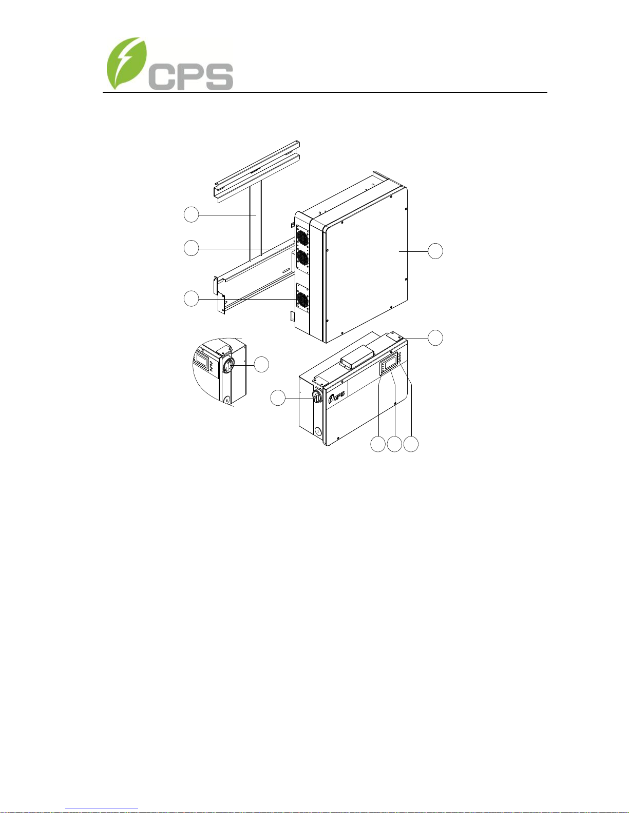
2.5 Appearance Description
1
3
4
4
9
2
5 6 7
8
Figure 2-3 Appearance sketch of CPS SCA23/28KTL-DO series inverter
Main items of the inverter:
1) Main housing of the inverter
2) Wiring box of the inverter
3) Mounting bracket
4) External cooling fans
5) LED indication lights
6) LCD display
7) Key buttons
8) DC switch: DC power on/off
9) AC switch: AC power on/off
12
Chapter 3 Installation
Below is the installation procedure for the inverter. Please read carefully and
install the product step-by-step.
Before installation, please check that the following items are included in
the package:
Table 3-1 Main items
No.
Item
Q’ty
Note
(1)
Main housing of the PV
inverter
1 (2)
Wiring box of the PV
inverter
1
(3)
Mounting bracket
1
Upon which inverter is hung and
mounted onto a wall
(4)
User manual
1
Installation and operation manual
(5)
Accessory kit
1
Contains all necessary accessories
The (5) Accessory kit contains items listed below:
Table 3-2 Accessories
No.
Item
Q’ty
Note
(1)
M8 Expansion tubes
8
For mounting bracket
(2)
M8×25 assembling bolts
8
For mounting bracket
(3)
M6X16 screw
6
For wiring box and main housing; 2
spare parts
13
(4)
M5X10 screw
8
For mounting bracket and inverter,
external ground connection
(5)
M3X8 screw
2
For Partition plate; 1 spare part
(6)
M5 flange nut
2
For internal ground stud connection; 1
spare part
(7)
Lifting eye nut M10
2
For lifting the main housing
(8)
OT type terminal
2
For ground connection
(9)
Pre-insulated end
ferrule for AC side
5
For AC output cables, 1 spare part
(10)
Pre-insulated end
ferrule
8
For ground cables
(11)
Pre-insulated end
ferrule for DC side
20
For DC input cables, 4 spare parts
(12)
RJ45 connecter
4
For RS485 or Ethernet
communication, 2 spare parts
(13)
5 pin connector
1
For RS485 communication
(14)
3 pin connector
1
For dry contact communication
(15)
Partition plate
1
For partition signal cable and the
power cable
INSTRUCTION:
The items in the accessory kit table above are for the standard
configuration. The accessories may vary if optional parts are
purchased.

14
3.1 Recommendations before installation
Check that the product environmental specifications (protection degree,
operating temperature range, humidity and altitude, etc) meet the
requirements of the specific project location;
Make sure that the power grid voltage is within normal range;
Ensure that the local electricity supply authority has granted permission
to connect to the grid;
Ensure that local code requirement is met by enabling the AFCI function
from the LCD screen. This feature is disabled by default but can be
enabled in the field.
Installation personnel must be qualified electricians or people who have
received professional training;
Sufficient space is provided to allow the inverter cooling system to
operate normally;
Install the inverter away from flammable and explosive substances;
Avoid installing the inverter in locations that exceed the temperature
limits specified in the inverter data sheet to limit undesirable power loss;
Do not install the inverter near the electromagnetic source which can
compromise the normal operation of electronic equipment;
15
3.2 Mechanical installation
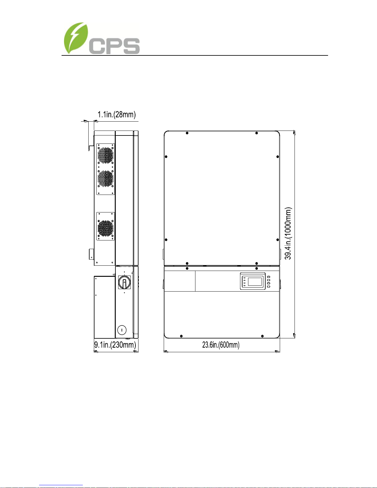
1) Dimensions
DC DISCONNECT
Figure 3-1 Dimensions of CPS SCA23/28KTL-DO series inverter
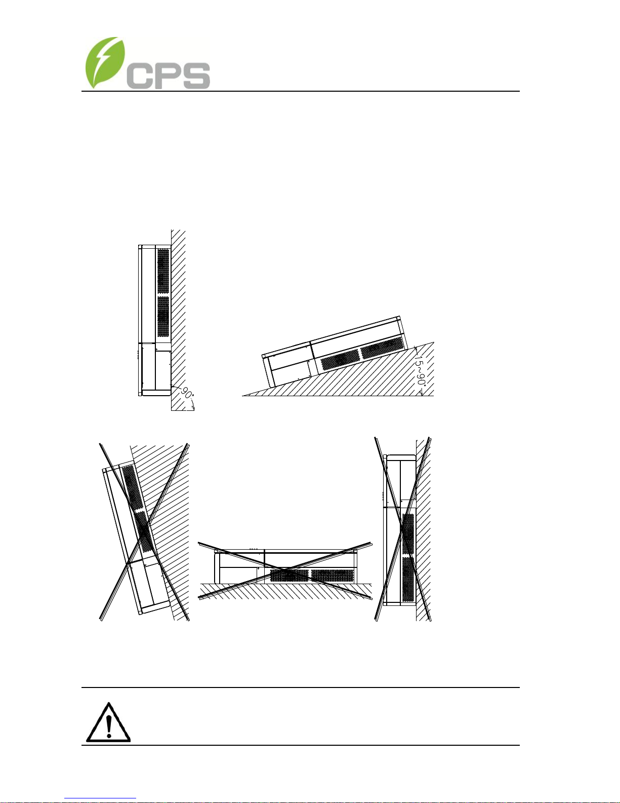
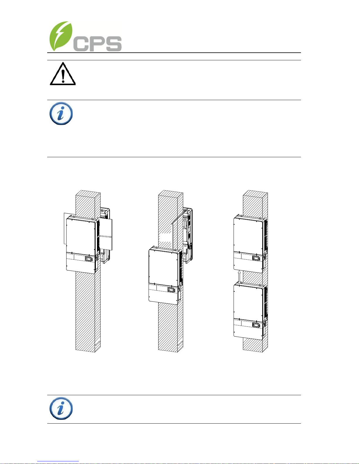
2) Installation method (see Figure 3-2):
Make sure that the mounting structure (wall, rack, etc) is suitable to support
the inverter weight. Follow the mounting guidelines below:
(a) If the location permits, install the inverter vertically.
16
(b) If the inverter cannot be mounted vertically, it may be tilted backward
by no lower than 15 degrees from horizontal.
(c) Do NOT mount the inverter leaning forward.
(d) Do NOT mount the inverter in a horizontal position (<15 degrees).
(e) Do NOT mount the inverter upside down.
(a)
(c) (d) (e)
(b)
Figure 3-2 Mount the inverter correctly
NOTICE:
When the inverter is mounted backward by ≥15° outdoor, shield
17
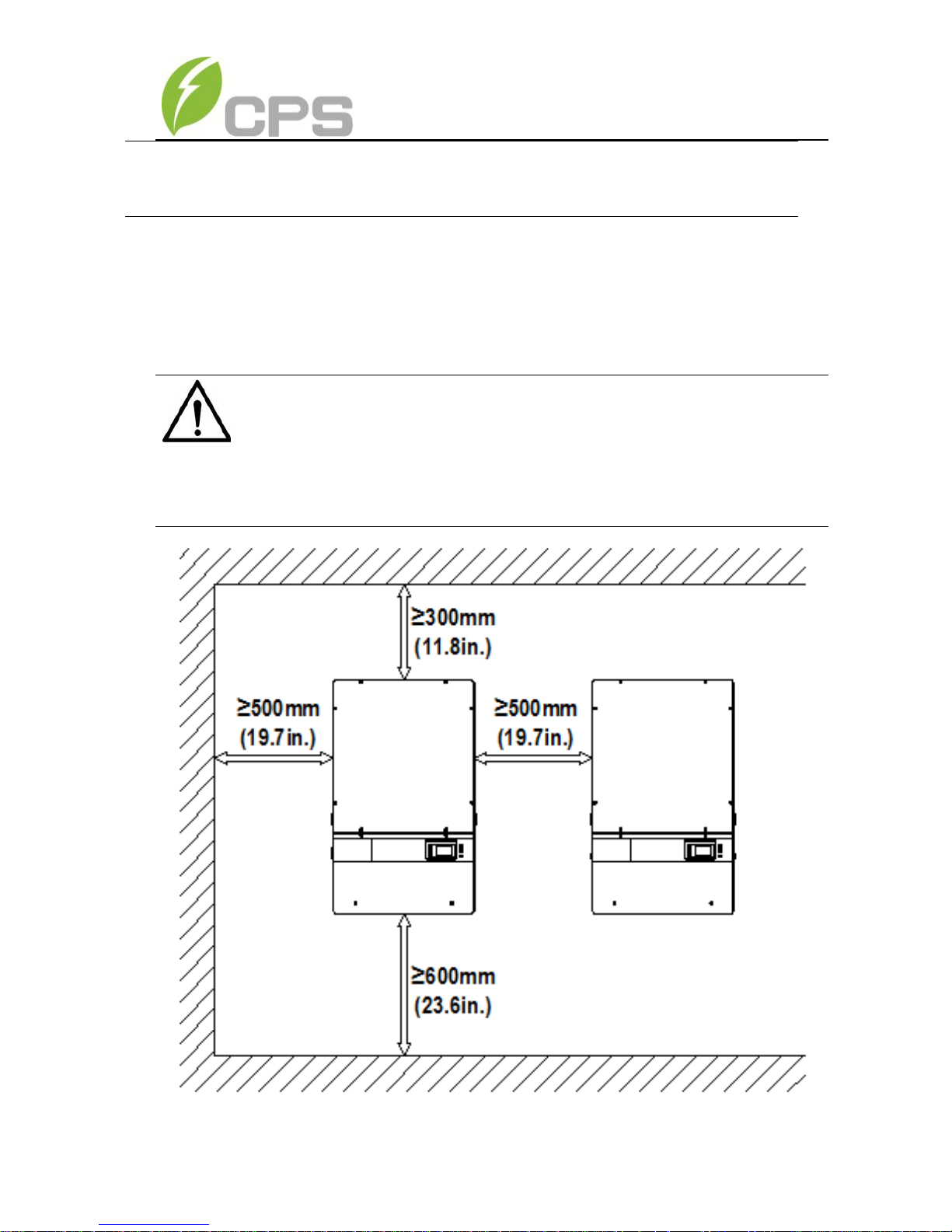
3) Installation space requirement (see Figure 3-3):
The distances between the inverters or the surrounding objects should meet
the following conditions:
Figure 3-3 Inverter wall mounting dimensions
cover is recommended to be installed above the inverter to avoid
direct sunlight.
NOTICE:
The spacing between two adjacently mounted inverters should be
≥500mm (19.7 inches). Ensure that the air space around the inverter
is well ventilated.
18
¡ Ý200mm
(7.9in.)
¡ Ý300mm
(11.8in.)
¡ Ý600mm
(23.6in.)
¡ Ý300mm
(11.8in.)
¡ Ý300mm
(11.8in.)
Figure 3-4 Inverter pillar mounting dimensions
NOTICE:
The installation clearance between two inverters needs to be
increased when the ambient temperature is higher than 45℃.
INSTRUCTION:
If the inverter is tilted backward by no lower than 15° from horizontal,
the bottom clearance distance can be reduced according to specific
conditions.
INSTRUCTION:
If the inverter is installed in open air on metallic brackets (instead of
19
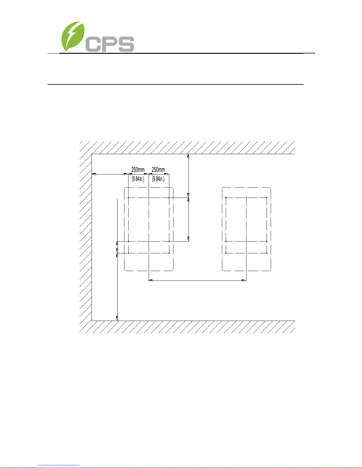
4) Mount the inverter onto the bracket
(1) Mark the 8 holes on the bearing surface for mounting the bracket as
shown in Figure 3-5;
813mm(min.)
425mm(min)
550mm(min.)
522mm
140mm(5.51in.)
1100mm(min.)
(21.7in.)
(16.7in.)
(32in.)
(43.3in)
(20.55in.)
Figure 3-5 Dimensions of holes on the bearing surface
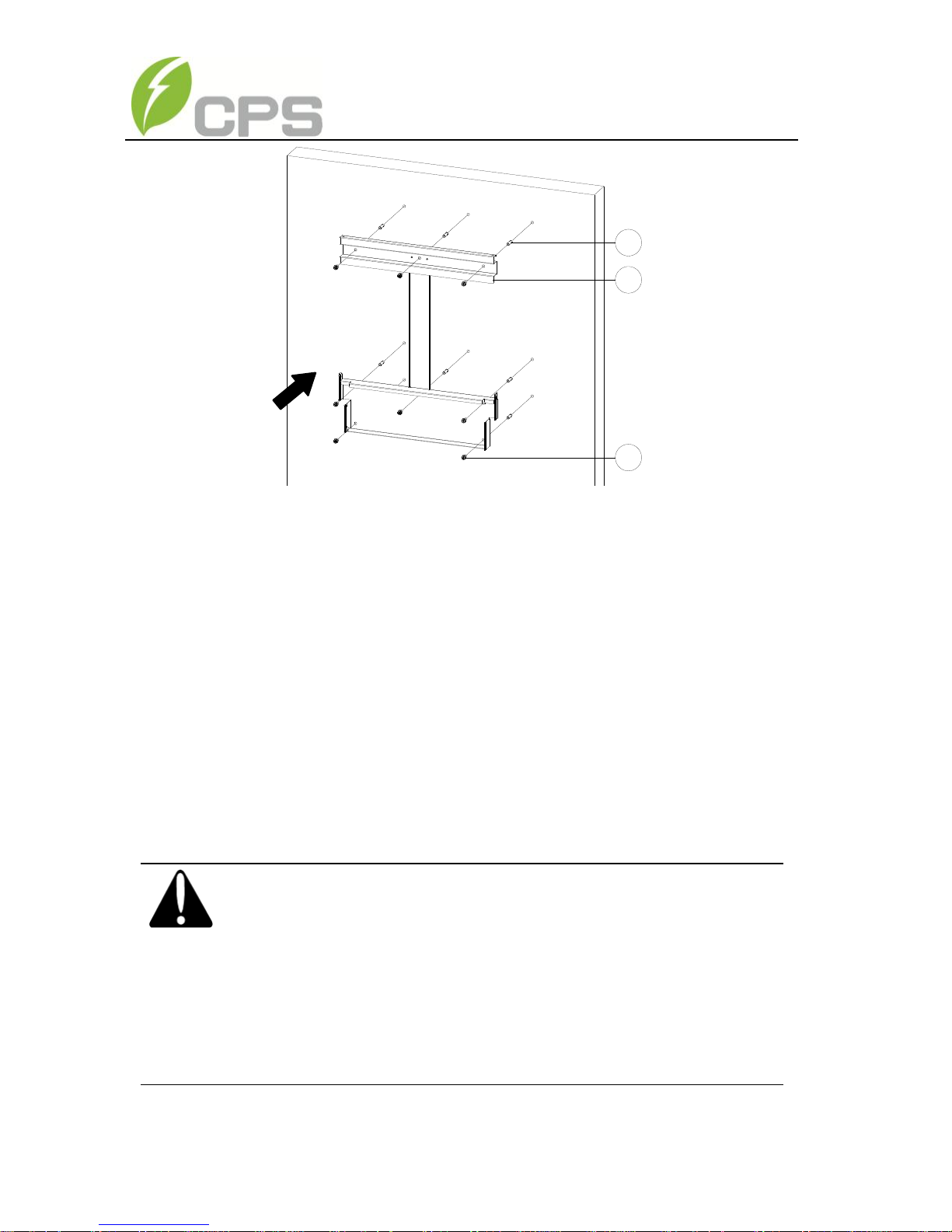
(2) Drill holes at the marked positions with a 10mm (0.4in.) drill and put the
M8 expansion tubes① into the holes; Fasten the mounting bracket② with
the M8x25 assembling bolts③ in the accessory kit.
Tool: Electric drill (Ф10mm/0.4in. head), No. 13 wrench
solid wall), the top clearance distance can be reduced to as minimum
as 100mm (3.94in.).
20
1
2
3
Figure 3-6 Secure the mounting bracket
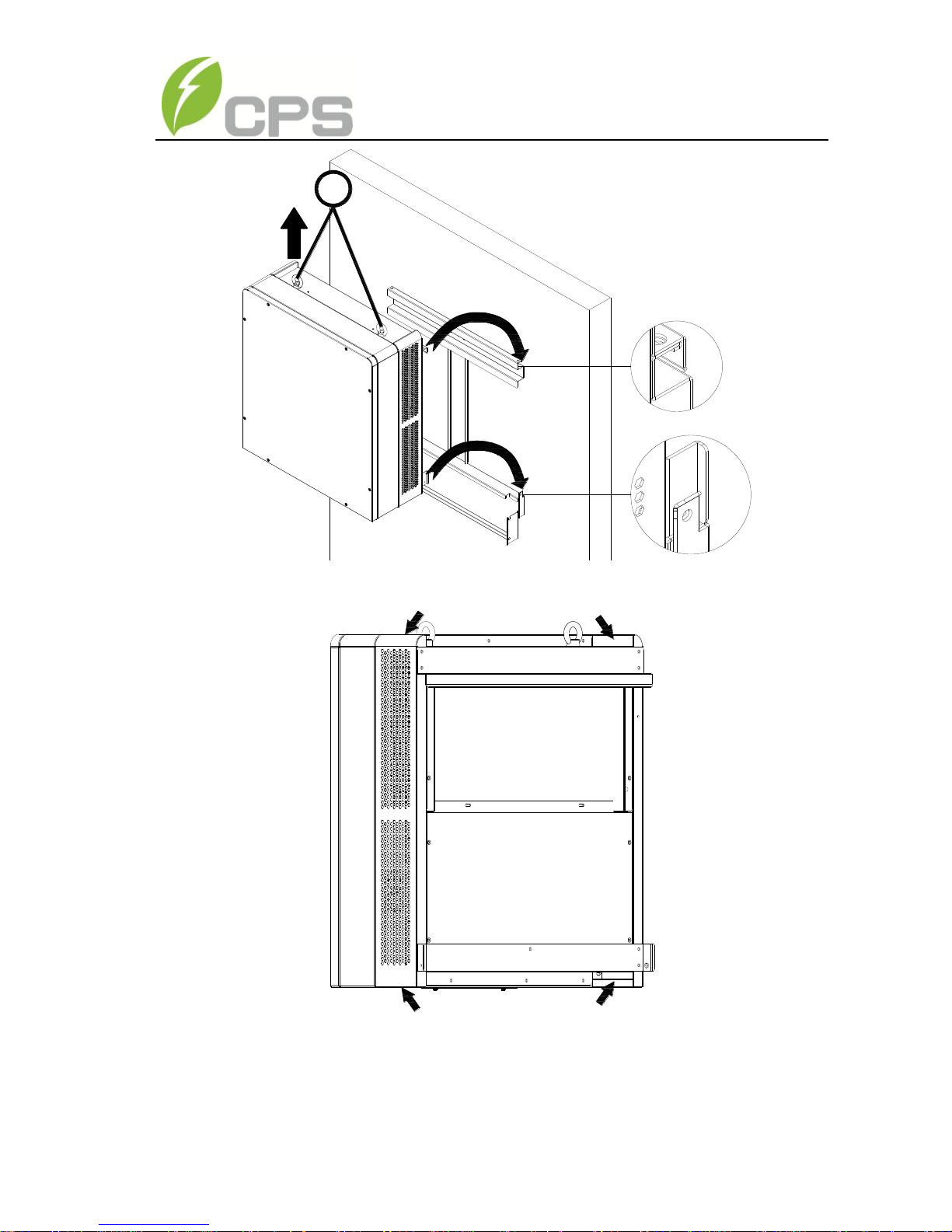
(3) Hang the inverter onto the mounting bracket as shown in Figure 3-7 and
Figure 3-8;
Lift mounting: Take out the lifting eye nut M10 (2pcs) from the
accessory kit, and screw them on the bolts at the top of the inverter. Use
sling rope or bar (inserted through both lifting eye nuts) to lift the inverter
onto the bracket. The minimum angle between the two sling ropes should
be less than 90 degrees.
Manual mounting: Two people grab the handle positions marked in
Figure 3-8, and mount the inverter onto the bracket.
CAUTION:
The main housing of the CPS SCA23/28KTL-DO series inverter is
about 46.5kg (≈102.5 pounds).
Please ensure the mounting is properly installed before hanging
the the inverter on the bracket. It is recommended to have at least
2 people to mount the inverter due to the weight of the equipment.
21
Figure 3-7 Mount the main housing on the bracket by lifting
Figure 3-8 Position of grab handle
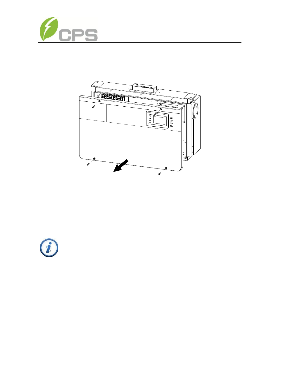
(4) Install the wiring box
① Remove the cover plate at the bottom of the main housing. (see Figure
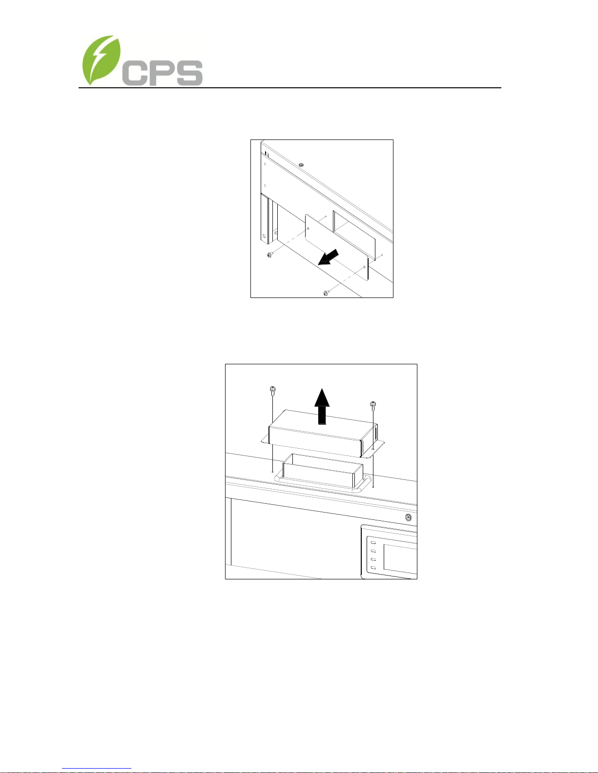
22
3-9)
Tool: No.2 Phillips head screwdriver
Figure 3-9 Cover plate of the main housing
② Remove the cover board at the top of the wiring box (see Figure 3-10)
Figure 3-10 Cover board of the wiring box
Save the cover board and screws, and fix the board on the left side of the
wiring box after the wiring box is attached to the inverter housing (see
step 6, Figure 3-13)
Tool: No.2 Phillips head screwdriver
③Insert the wiring box to the main housing, and use M6x12 screws (4pcs)
23
to attach the wiring box to the inverter housing. (see Figure 3-11)
Tool: No. 10 Wrench, torque value of 2.8N.m
Figure 3-11 Installation of the wiring box
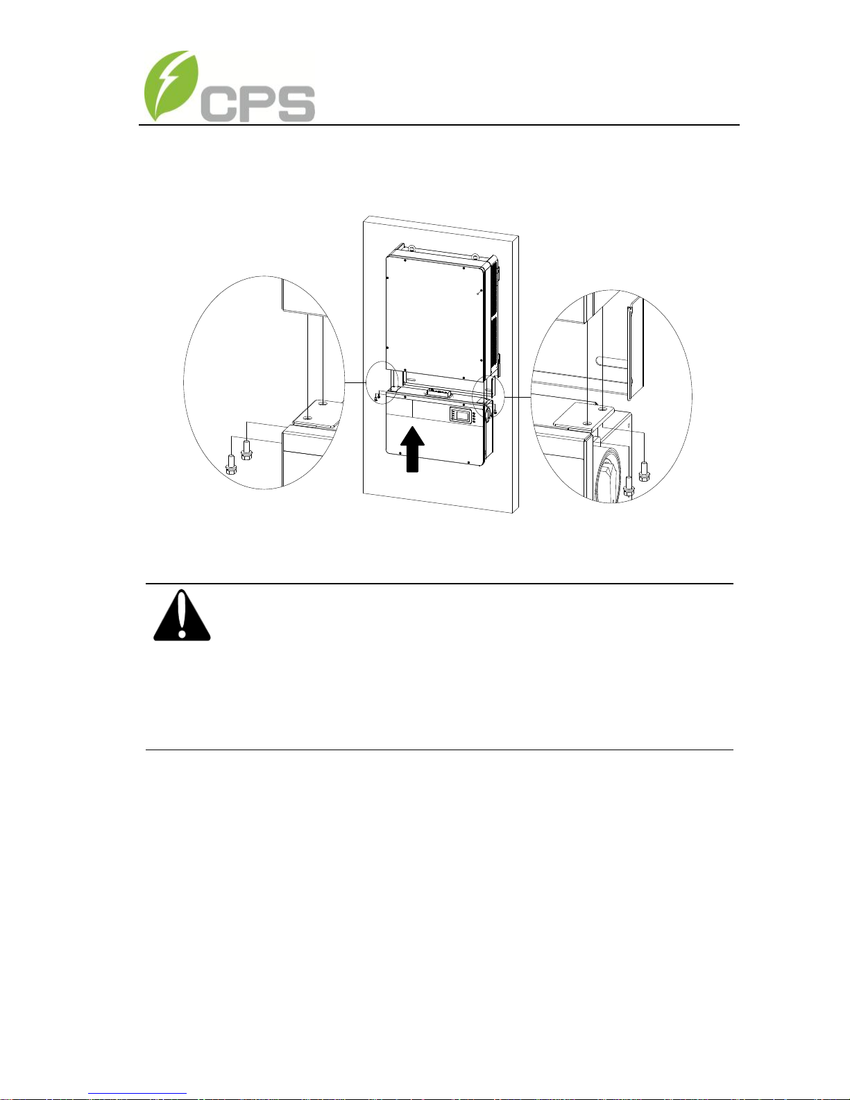
(5) Attach the main housing and the wiring box to the mounting bracket with
the M5x10 bolts (6 pcs). (see Figure 3-12)
Tool: No.2 Phillips head screwdriver, torque value of 1.6N.m
CAUTION:
The total weight of the CPS SCA23/28KTL-DO series inverter is
about 55kg (≈122 pounds).
Please ensure the mounting is properly installed before hanging the
the inverter on the bracket.
24
Figure 3-12 Fix the main housing and wiring box on the bracket
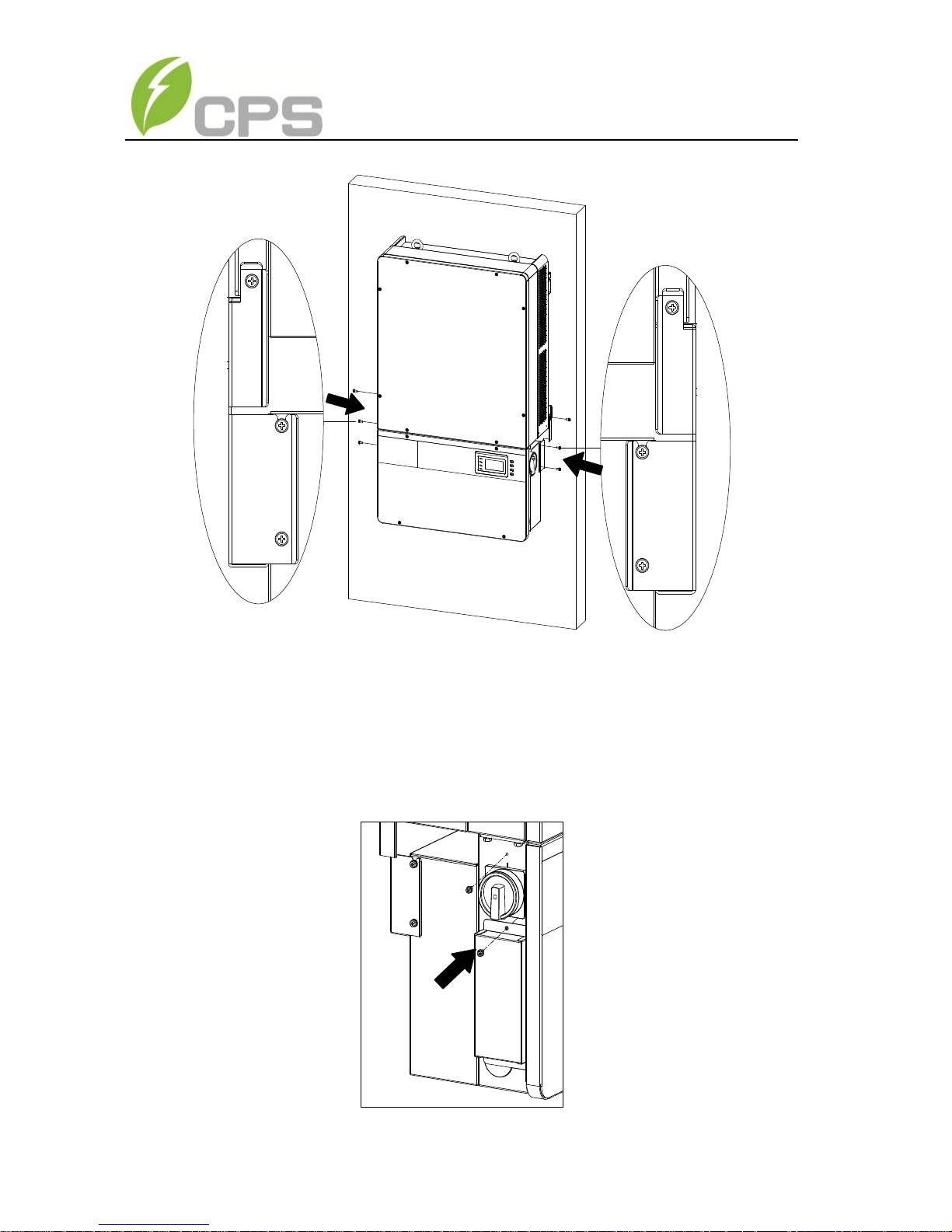
(6) Attach the cover board shown in Figure 3-10 to the left side of the wiring
box. (see Figure 3-13)
Tool: No.2 Phillips head screwdriver, torque value of 1.2N.m
Figure 3-13 Attach the cover board to the left side of the wiring box
25
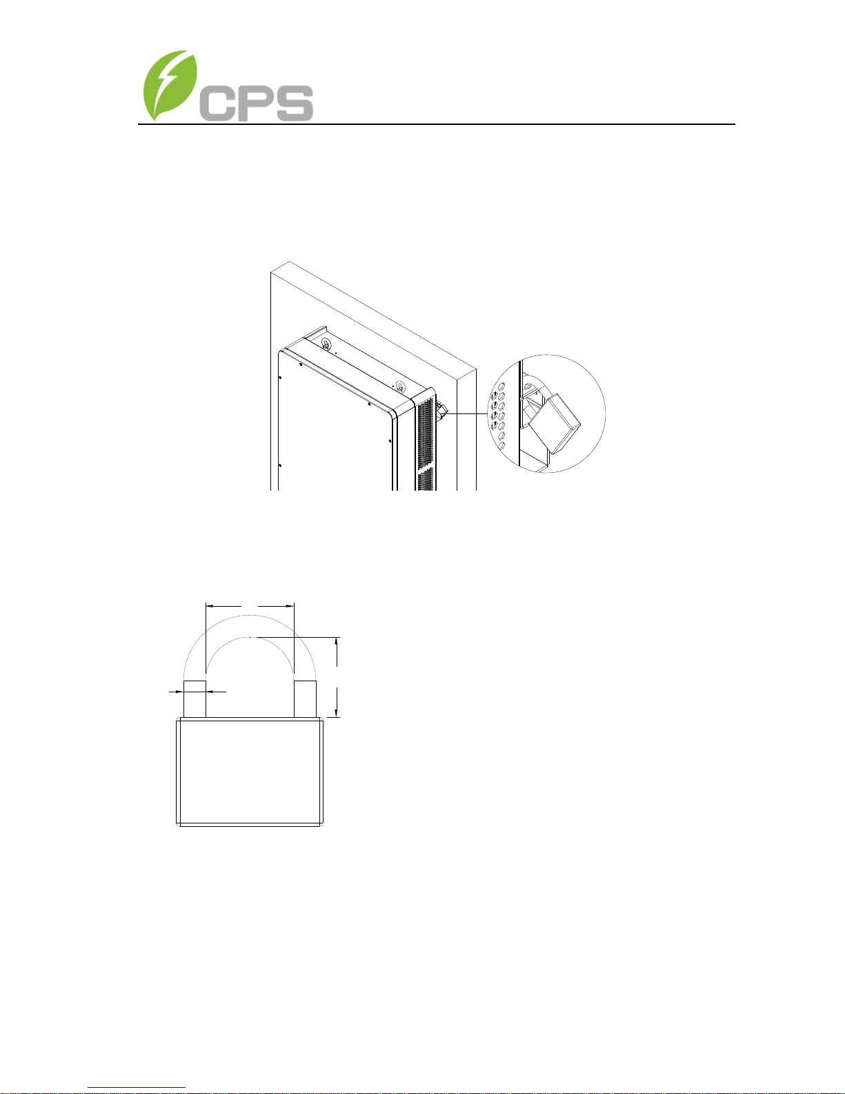
(7) Optional - Install an anti-theft padlock when the installation is complete.
The anti-theft padlock is used to prevent the inverter from being stolen
when the equipment is installed outdoors. You can lock the inverter on the
bracket, as shown in Figure 3-14:
Figure 3-14 Location of the anti-theft padlock
The anti-theft padlock should meet the requirement of the dimensions
shown in Figure 3-15:
B
C
A
Figure 3-15 The dimensions of anti-theft padlock
Recommended lock size:
A: Ф3~6mm
B: 20~50mm
C: 20~50mm
26
5) Removing/Replacing the wire box cover:
(1) Use a 3mm (0.12in.) Hex screwdriver to remove the 4 screws on the
wiring box and take off the cover. (see Figure 3-16(a))
Figure 3-16(a)- Take off the cover of the wiring box
(2)To replace the cover use a 3mm (0.12in.) Hex screwdriver to replace the 4
screws on the cover.
INSTRUCTION:
It is important to use a hand tool (e.g. Hex key, Allen key/socket or
T-handle, 3mm) and not power drivers or other types of screw drivers.
Also, it is important to hold the cover in alignment with balanced force
across the cover, not weighted toward any edge, for screw to
Pem®-nut alignment. Partially engage all four screws to Pem®-nuts a
few rotations before tightening any one screw. This is important to
maintain alignment and avoid thread damage.

27
INSTRUCTION:
We posted on our website, www.chintpowersystems.com, under the
Service menu a ‘how to’ video showing the best technique for
installing the wire-box cover.
28
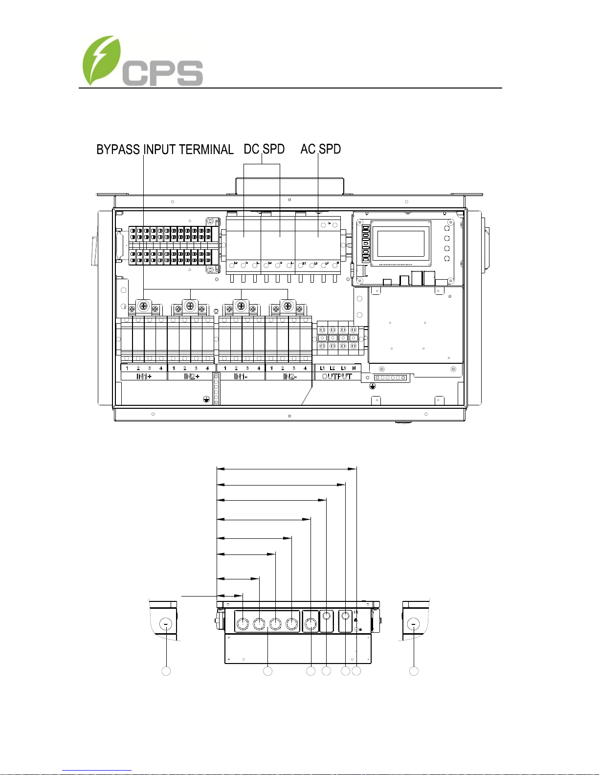
3.3 Electrical installation
The connection interface of CPS SCA23/28KTL-DO series inverter:
Figure 3-16(b) : Full view of wiring box with options.
Figure 3-17 External connection ports
WARNING:
High touch current .
Earth connection essential
before connecting supply.
For more details please
see the user manual.
DC INPUT AC OUTPUT
COMM. PORT ANTENNA
16 2
3 475
3.8 in.
6.2 in.
8.5 in.
10.9 in. (277mm)
13.7 in. (347mm)
15.9 in. (405mm)
18.7 in. (475mm)
(97mm)
(157mm)
(217mm)
20.3 in. (515mm)
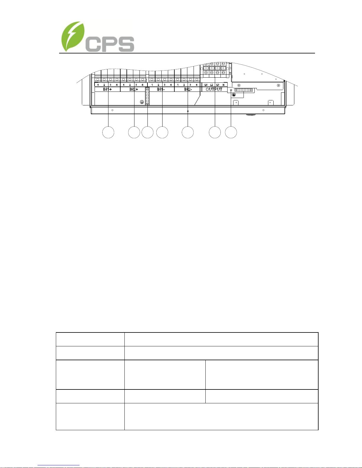
29
Figure 3-18 Internal connection points
① Knockout holes for DC input cable, 1-1/4” or 1”
② Knockout hole for AC output cable, 1-1/4” or 1”
③ Knockout hole 1/2inch & 3/4inch,for comm. cable
④ Knockout hole 1/2inch & 3/4inch,for comm. cable,reserved
⑤ External ground connection point
⑥ Side hole for DC input cable, 1-1/4”
⑦ Side hole for AC output cable, 1-1/4”
⑧ DC input fuse holders
⑨ AC output terminal block
⑩ Internal ground connection point & grounding studs
Choose the cables for inverters according to the following configuration table:
Table 3-3 Cables specifications
Position
Cable
DC input (﹢/﹣)
DC cables specifications refer to Table3-6
AC output
(L1/L2/L3/N)
Cable #10~2AWG
#8AWG cable recommended
PE
Cable #10~6AWG
#8AWG cable recommended
RS485
communication
UTP CAT-5e or 3x#22~18AWG communication cable (eg.
Belden 3106A)
8 8
8 8
9 1010
30
3.3.1 DC connection
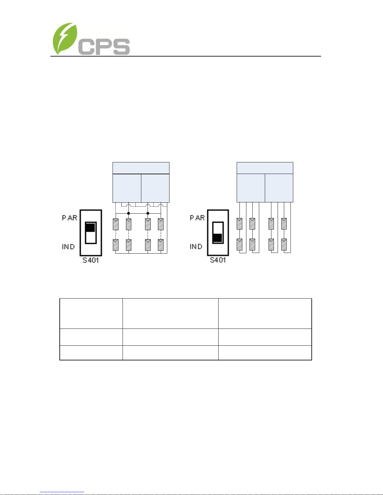
1) Working mode
CPS SCA23/28KTL-DO series inverter has two PV input sections: DC
Input-1 and DC Input-2. These two sections can work under “Parallel mode” or
“Independent mode”. (see Figure 3-19)
Under Parallel mode, the two PV input sections share one MPP Tracker;
Under Independent mode, each PV input section works with one MPP Tracker.
n1=n2 =n3=n4
DC
Input-1DCInput-2
Inverter
n1 n2 n3 n4
DC
Input-1DCInput-2
Inverter
n1 n2 n3 n4
n1=n2 n3=n4
Figure 3-19(a) Parallel mode Figure 3-19(b) Independent mode
Table 3-4 DC input power specification
Inverter model
Max. DC input power
Rated DC input power
of each input section
SCA23KTL-DO
31kW
15.5kW
SCA28KTL-DO
38kW
19kW
Remarks: The standard configuration is “Parallel mode”. If it needs to
switch to the “Independent mode”, please take the follow:
1. Remove the cover of the wiring box. Use 3mm (0.12in.) Hex
screwdriver to remove the 4 screws on the wiring box and take off the
cover. (see Figure 3-16(a))
2. Remove the protection cover. (see Figure 3-20a)
3. Use No.2 Phillips head screwdriver to remove the jumper busbar,
 Loading...