

CPS SC14KTL-DO/US-208 Installation And Operation Manual
CPS SC Series Grid-tied PV Inverter
CPS SC14KTL-DO/US-208
Installation and Operation Manual
Ver 1.1

CHINT POWER SYSTEMS AMERICA CO., LTD.
Web: www.chintpower.com/na
Email: americasales@chintpower.com
Service Hotline: 855-584-7168
Address: 700 International Parkway
Suite 102
Richardson TX 75081
SHANGHAI CHINT POWER SYSTEMS CO., LTD. All rights reserved.
Specifications and designs included in this manual are subject to change without notice.
CHINT POWER 2013/09-MKT PN: 9.0020.0117B0

Table of Contents
Before You Start… ...................................................................................... 1
Chapter 1 IMPORTANT SAFETY INSTRUCTIONS .................................. 2
Chapter 2 Overview .................................................................................. 5
2.1 Inverter for grid-tied PV systems ................................................... 5
2.2 Product features ............................................................................ 5
2.3 Circuit structure design .................................................................. 6
2.4 Appearance description ................................................................. 7
Chapter 3 Installation ............................................................................... 8
3.1 Recommendation before installation ............................................. 9
3.2 Mechanical installation .................................................................. 9
3.3 Electrical installation ...................................................................... 17
3.3.1 DC connection ............................................................................ 17
3.3.2 AC and ground connection ......................................................... 19
3.3.3 Communication connection ........................................................ 22
Chapter 4 Operation ................................................................................. 32
4.1 Start-up .......................................................................................... 32
4.2 Shut-down ..................................................................................... 32
4.3 Operation mode............................................................................. 32
4.4 Grid connection and power generation .......................................... 34
4.5 Fault shutdown .............................................................................. 35
Chapter 5 User Interface .......................................................................... 43
5.1 Description of LCD panel .............................................................. 43
5.2 Operation state .............................................................................. 44
5.3 Interface and menu functions ........................................................ 45
5.3.1 Interface types ............................................................................ 45
5.3.2 Main operation interface ............................................................. 47
5.3.3 Operation information ................................................................. 47
5.3.4 Alarm .......................................................................................... 48
5.3.5 History ........................................................................................ 49
5.3.6 System setup.............................................................................. 50
5.3.7 Power/PF ................................................................................... 52
5.3.8 Power Control............................................................................. 53
5.3.9 System protection parameters setup .......................................... 54
Chapter 6 Technical Data ......................................................................... 58
Chapter 7 Limited Warranty..................................................................... 61


1
Before You Start…
This manual contains important information regarding installation and safe
operation of this unit. Be sure to read this manual carefully before using.
Thanks for choosing this CPS Grid-tied PV Inverter. This PV Inverter is a high
performance and highly reliable product specifically designed for the North
American Solar market.
If you encounter any problems during installation or operation of this unit, first
check this manual before contacting your local dealer or supplier. Instructions
inside this manual will help you solve most installation and operation
difficulties.
Please keep this manual on hand for quick reference.
2
Chapter 1 IMPORTANT SAFETY INSTRUCTIONS
(SAVE THESE INSTRUCTIONS)
Please read this user manual carefully before product installation. CPS
reserves the right to refuse warranty claims for equipment damage if the user
fails to install the equipment according to the instructions in this manual.
Warnings and symbols in this document
DANGER:
DANGER indicates a hazardous situation which, if not avoided, will
result in death or serious injury.
WARNING:
WARNING indicates a hazardous situation which, if not avoided,
could result in death or serious injury.
CAUTION:
CAUTION indicates a hazardous situation which, if not avoided,
could result in minor or moderate injury.
NOTICE:
NOTICE indicates a hazardous situation which, if not avoided, could
result in equipment working abnormally or property loss.
INSTRUCTION:
INSTRUCTION indicates important supplementary information or
provides skills or tips that can be used to help you solve a problem or
save you time.

3
Markings on the product
HIGH VOLTAGE:
The product works with high voltages. All work on the product
must only be performed as described in this document.
HOT SURFACE:
The equipment is designed to meet international safety
standards, but surfaces can become hot during operation. Do not
touch the heat sink or peripheral surfaces during or shortly after
operation.
EARTH GROUND:
This symbol marks the location of grounding terminal, which
must be securely connected to the earth through the PE
(protective earthing) cable to ensure operational safety.
DANGER:
Please disconnect the inverter from AC grid and PV modules before
opening the equipment. When the PV array is exposed to light, it
supplies DC voltage to this equipment. Make sure hazardous high
voltage and energy inside the equipment has been discharged.
Do not operate or maintain the inverter until at least 5 minutes after
disconnecting all sources from DC and AC sides.
WARNING:
All the installation and cable connections should be performed only
by qualified technical personnel. Disconnect the inverter from PV
modules and the Power Grid before maintaining and operating the
equipment.
4
NOTICE:
This inverter is designed to connect AC power only to the public grid.
Do not connect the AC output of this equipment directly to any
private AC power equipment.
CAUTION:
CPS SC14KTL-DO inverter is approx 64kg (≈141 pounds).
Please ensure the mounting is properly installed before hanging the
the inverter on the bracket.
5
Chapter 2 Overview
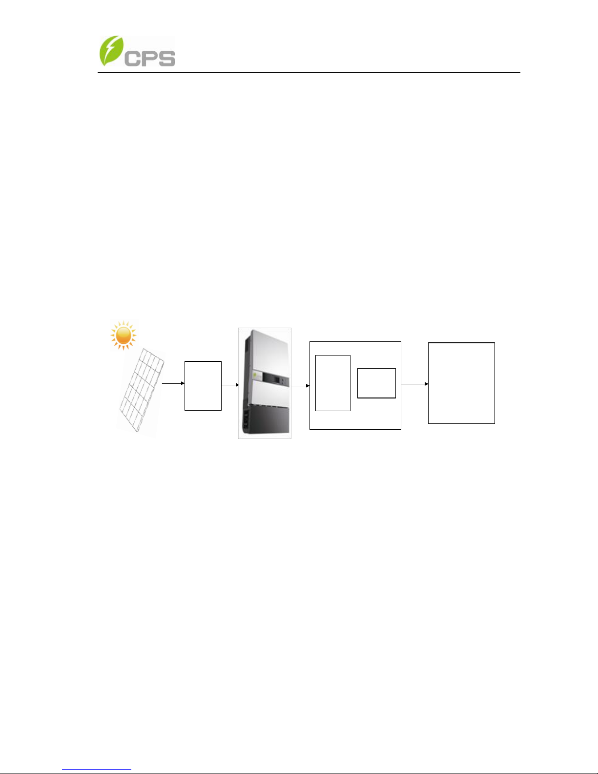
2.1 Inverter for grid-tied PV systems
CPS SC14KTL-DO/US-208 inverter is suitable for use with various
commercial rooftop systems and distributed power station systems. Normally,
the system mainly consists of PV modules, DC power distribution equipments,
PV inverter and AC power distribution equipments (Figure 2-1). The inverter
converts the DC from PV modules to AC with the same frequency and phase
as the AC grid. All or part of the AC power is supplied to local loads, and the
surplus power is supplied to the electricity grid.
DC power
distribution
equipments
AC Grid
Bidirectional
electric meter
AC power
distribution
equipments
Figure 2-1 Grid-tied PV system
2.2 Product features
The two-MPPT design has the benefit of increasing the power generating
efficiency of the whole PV system. The inverter has 2 MPPTs, so a separate
array can be controlled by an independent Maximum Power Point Tracking
(MPPT) control circuit. This means that the two arrays can be installed in
different positions and orientations.
The transformerless design of inverter with the benefit of small size, light
weight, high power density, flexible installation and convenient maintenance
provides the best cost performance for the whole PV system.
6
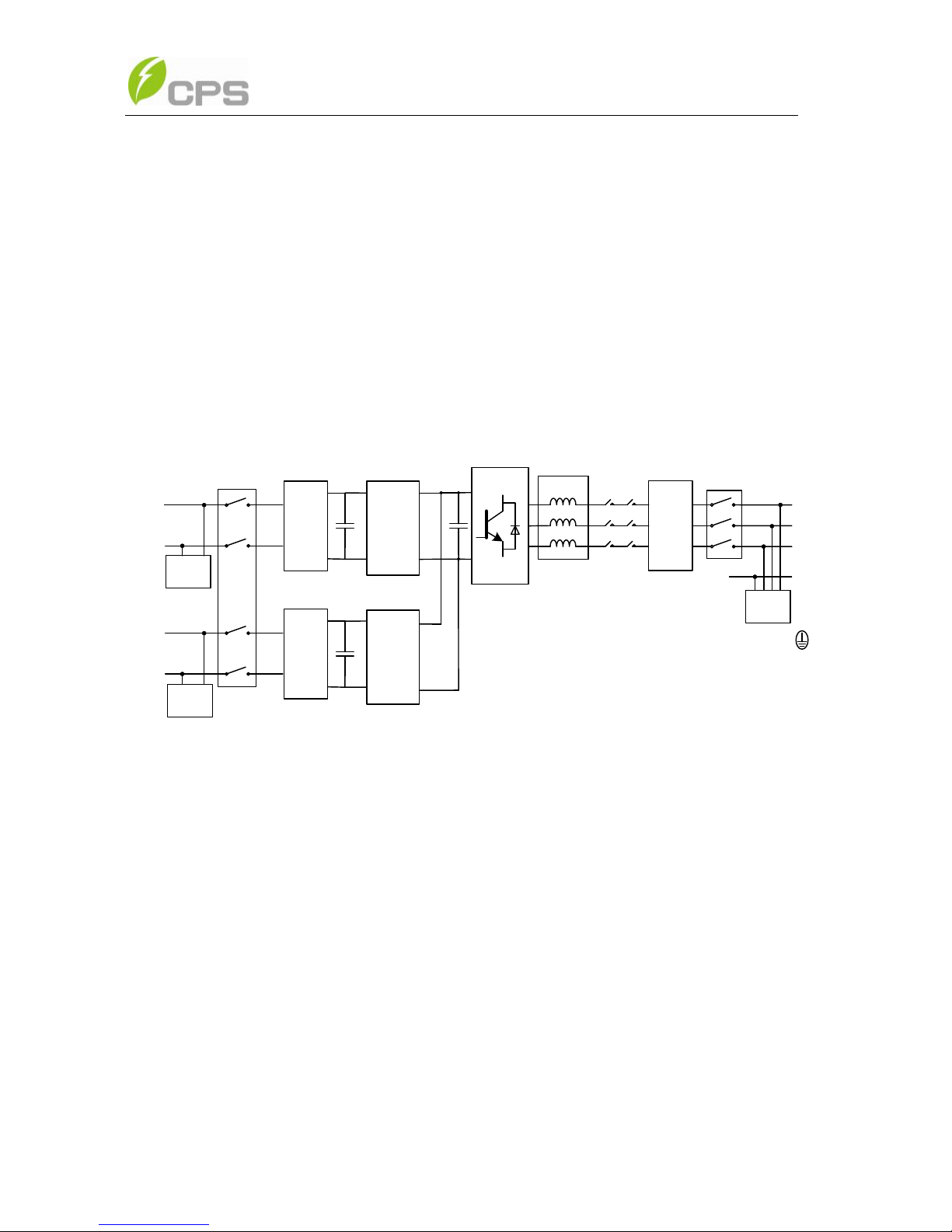
2.3 Circuit structure design
The basic schematic diagram of CPS SC14KTL-DO/US-208 is shown in
Figure 2-2. The input DC passes through surge protection circuitry, DC EMI
filter, and the boost circuit to achieve maximum power tracking and boost up
voltages. The inverter converts the DC energy to 3-phase AC energy. The high
frequency components of AC voltage are removed with a line filter. Then the
3-phase AC energy is sent through two-stage relays and EMI filter to produce
high quality AC power.
EMI
Filter
INV
EMI
Filter
L1
L2
L3
N
PE
Filter
Lightin
g surge
DC_Switch
PV1+
PV1-
DC/DC
EMI
Filter
PV2+
PV2-
DC/DC
AC_Switch
Lightin
g surge
Lightin
g surge
Figure 2-2 Schematic diagram of CPS SC14KTL-DO/US-208
7
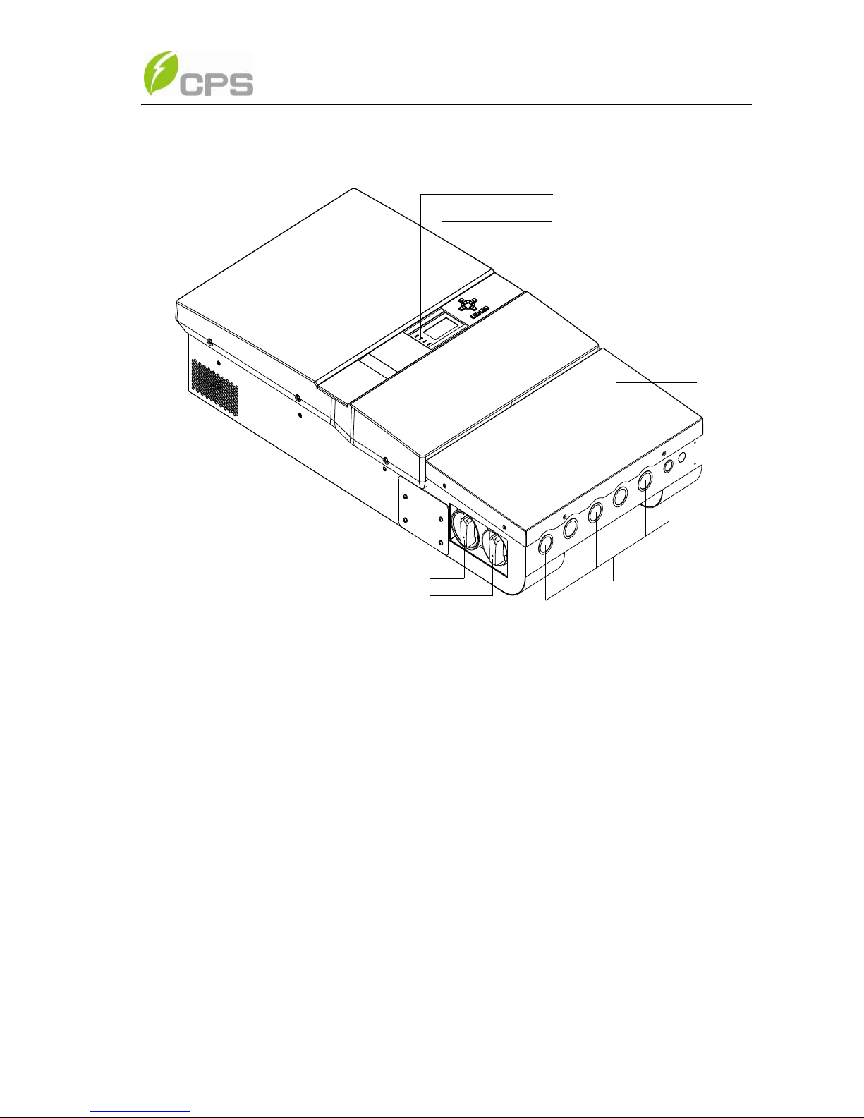
2.4 Appearance description
1
2
3
4
8
6
5
7
Figure 2-3 Appearance sketch of CPS SC14KTL-DO/US-208
Description of main items of CPS SC14KTL-DO/US-208 (See Figure
2-3):
1. LCD key buttons: operate the functions and change settings of inverter
2. LCD display: indicates data
3. LED indicator lights: indicate the status of inverter
4. Holes for cable entry
5. DC switch: control the DC power on and off
6. AC switch: control the AC power on and off
7. Main housing
8. Wiring box
8
Chapter 3 Installation
Below is the installation instruction of the inverter. Please read carefully
and install the product step-by-step.
Before installation, please check that the following items are included in
the package:
Table 3-1 Main items
No.
Item
Q’ty
Note
(1)
CPS
SC14KTL-DO/US-208
Grid-tied PV inverter
1
(2)
Mounting bracket
1
(3)
Installation and operation
manual
1
(4)
Warranty card
1
(5)
Accessory kit
1
contains all necessary
accessories
The (5) Accessory kit contains items listed below:
Table 3-2 Accessories
Item
Q’ty
Purpose
M8x25 Expansion
bolts&nuts
8 pairs
for bracket installation
OT type terminal
1
For ground cable
Pre-insulated end ferrule
20
16 for DC input cables, 4
for AC output cables
RJ45 connecters
4
for communication cables
Flange M5 nut
2
for ground cable

9
3.1 Recommendation before installation
Check that the product environmental specifications (protection degree,
operating temperature range, humidity and altitude, etc) meet the
requirements of the specific project location;
Make sure that the power grid voltage is within normal range;
Ensure that the local electricity supply authority has granted permission
to connect to the grid;
Installation personnel must be qualified electricians or people who have
received professional training;
Sufficient space is provided to allow the inverter cooling system to
operate normally;
Install the inverter away from flammable and explosive substances;
Avoid installing the inverter in locations that exceed the temperature
limits specified in the inverter data sheet to limit undesirable power loss;
Do not install the inverter near the electromagnetic source which can
compromise the normal operation of electronic equipment;
3.2 Mechanical installation
(1) Dimensions
The dimensions of CPS SC14KTL-DO/US-208 inverter are shown in
Figure 3-1.
INSTRUCTION:
The items in the accessory kit table above are for the standard
configuration. The accessories may vary if optional parts are
purchased.

10
21.42in
41.73in
8.46in
544mm
1060mm
215mm
Figure 3-1 Dimensions of CPS SC14KTL-DO/US-208
(2) Installation method
Make sure that the mounting structure (wall, rack, etc) is suitable to
support the inverter weight. Follow the mounting guidelines below:
(a) If the location permits, install the inverter vertically.
(b) If the inverter cannot be mounted vertically, it is allowed to be tilted
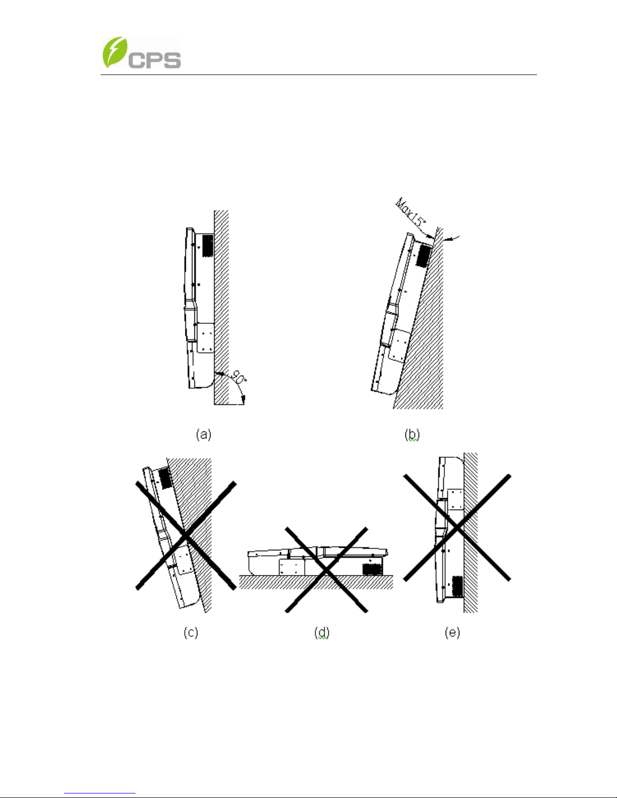
11
backward by Max. 15°.
(c) Do NOT mount the inverter forwards.
(d) Do NOT mount the inverter in a horizontal position.
(e) Do NOT mount the inverter upside down.
Figure 3-2 Mounting the inverter properly
(3) Space required for inverter mounting on the wall (see Figure 3-3)
The distances between the inverter and the surrounding objects should
meet the following conditions: two sides from the walls ≥300mm (11.81in.); top
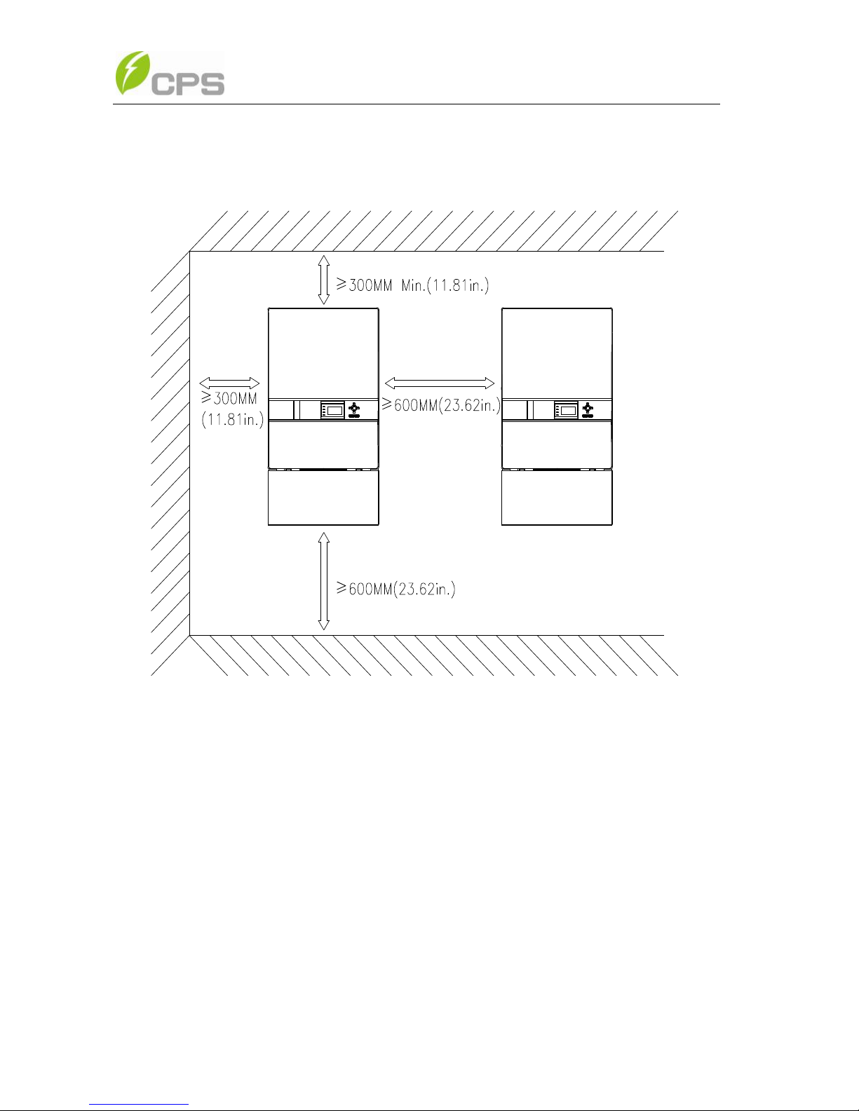
12
distance ≥300mm (11.81in.); bottom distance ≥600mm (23.62in.); the
minimum spacing between two inverters in parallel ≥600mm (11.81in.).
Figure 3-3 Inverter mounting dimensions
(4) Secure the bracket with bolts through the mounting holes and install
the inverter:
(a) Mark the 6 bolt holes for mounting the bracket as shown in Figure 3-4;
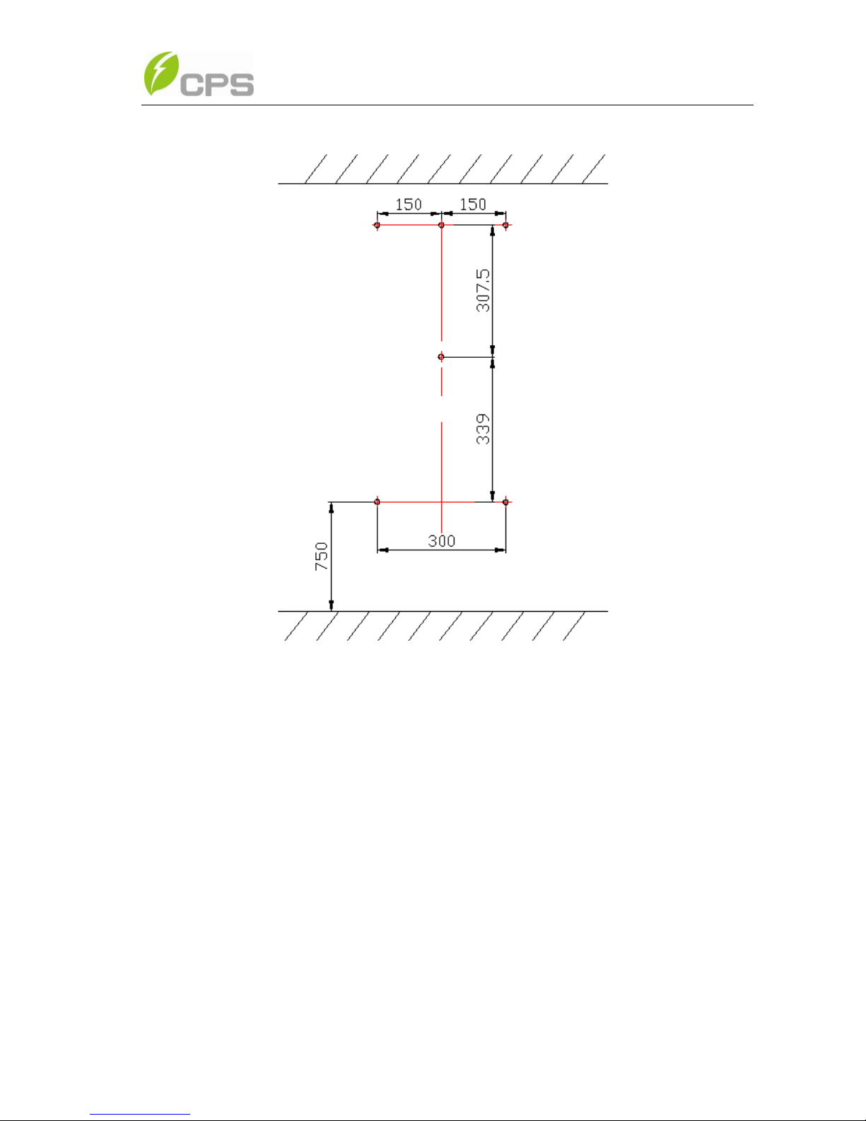
13
Figure 3-4 Bracket mounting dimensions
(b) Drill holes at the marked positions with a diameter of 0.4in. drill and
put the 6 expansion bolts into the holes;
(c) Take the mounting bracket out of the package and secure the
bracket on the wall with the 6 nuts in pair as shown in Figure 3-5;
14
Figure 3-5 Positions of bolt holes on the bracket
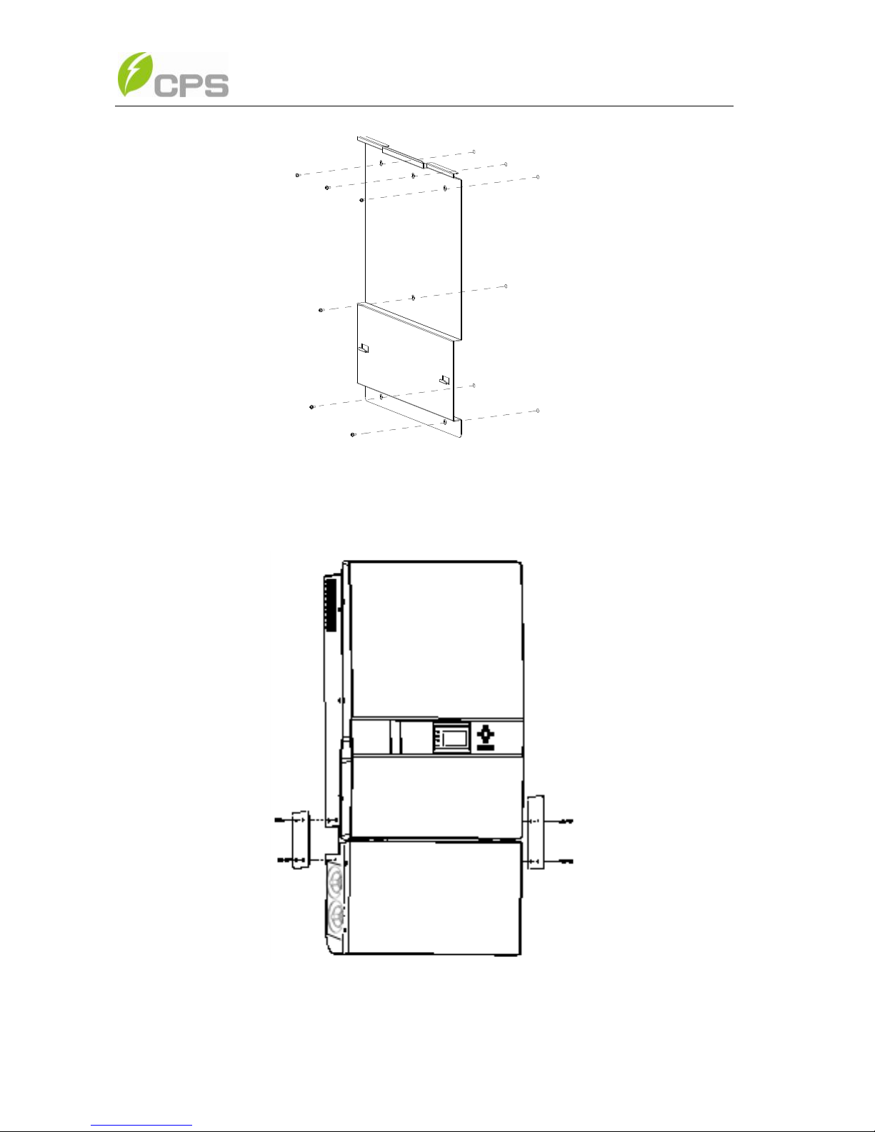
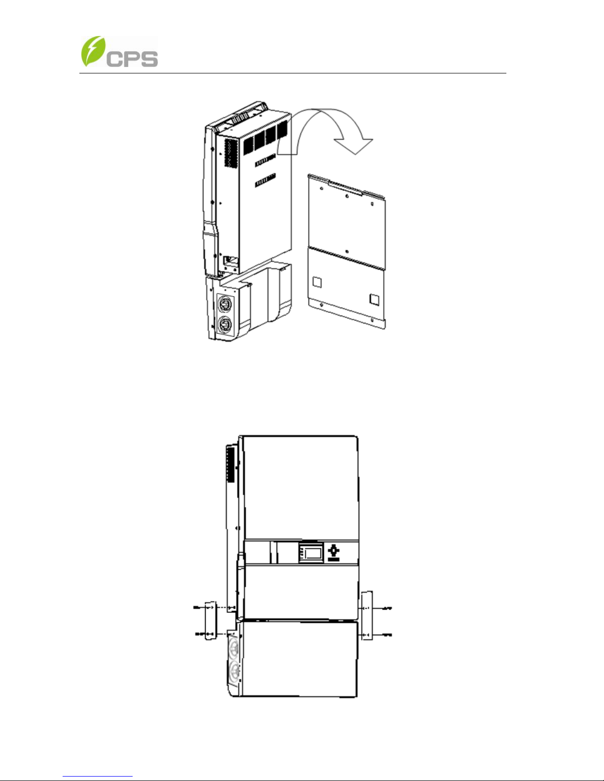
(d) Screw off the bolts and remove the two panels on both sides of the
inverter as shown in Figure 3-6;
Figure 3-6 Removal of panels before mounting inverter
(e) Two people grab at the position on each side (see Figure 3-7a), lift
up the inverter and then hang it on the bracket (see Figure
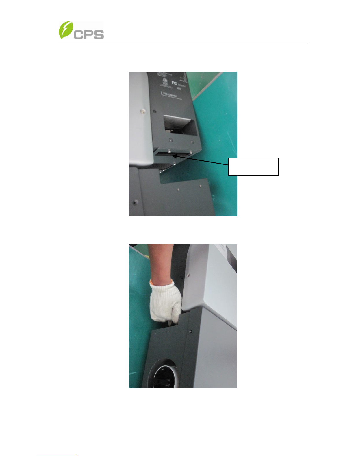
15
3-7b~c). Make sure the inverter is securely fixed on the bracket;
Figure 3-7a Mounting inverter on the bracket
Figure 3-7b Mounting inverter on the bracket
Hand Grab
16
Figure 3-7c Mounting inverter on the bracket
(f) Put the two removed panels back and secure them with 4 M4*12
bolts on each side, as shown in Figure 3-8.
Figure 3-8 Securing panels on both sides
 Loading...