

CPS FX134, FX1234, FX3030, FX134E, FX1234E Service Manual
...
FX Series Service Manual
Models: FX134, FX1234, FX3030
CPS AUTOMOTIVE RECOVER, RECYCLE, RECHARGE
1

Table of Contents
General Safety Instructions 2
Introduction 3
Summary of Operation 4-10
Section 1 Updating Program, Service Access, and Calibration Procedures 11-21
Section 2 Common Problems and Solutions 22-27
Section 3 Repair Procedures Component Service and Repair Instructions 28-41
Section 4 Reference Materials 42-50
PAGE
General Safety Instructions
Only qualified service personnel should service this unit. The service personnel should be qualified in
refrigerant and electrical service work. It will be necessary for the service technician to operate the unit
with the service covers removed. Please use extreme caution due to the presence of un-insulated live
electrical parts.
Danger- Electrical Shock Hazard. When servicing this equipment with the front cover opened, live
un-insulated electrical connections will be exposed. An Electrical Shock hazard could result in
severe injury or even death.
Danger- The unit’s recovery tank contains liquid refrigerant. Overfilling of the recovery tank may cause a
violent explosion resulting in severe injury or even death.
Danger- Only use CPS Automotive recommended recovery tanks with this unit. See distributor for
replacement tanks.
Danger- Avoid breathing refrigerant vapors and lubricant vapor or mist. Breathing high concentration
levels may cause heart arrhythmia, loss of consciousness, or even cause suffocation and death.
Caution- all hoses may contain liquid refrigerant under pressure. Contact with refrigerant may cause
frostbite or other related injuries. Wear proper personal protective equipment such as safety goggles and
gloves. When disconnecting any hose, please use extreme caution.
Caution- avoid breathing refrigerant vapors and/or lubricant mist. Exposure may irritate eyes, nose,
throat, and skin. Please read the manufacturers Material Safety Data Sheet for further safety information
on refrigerants and lubricants.
Caution- to reduce the risk of fire, avoid the use of extension cords thinner than NO. 14 awg.
(1,5m1,5mm²) to prevent the overheating of this cord please keep length to a minimum.
Caution- do not use this equipment in the vicinity of spilled or open containers of gasoline or other
flammable substances. Make certain that all safety devices are functioning properly before operating the
equipment.
Mixing of different refrigerants will cause this equipment and the mobile A/C system to prematurely fail.
Note: It is very expensive to destroy mixed or damaged refrigerants.
Make sure that recovery tank is placed on the load cell platform at all times. Failure to do so will disable
certain safety features of this unit.
2

Introduction
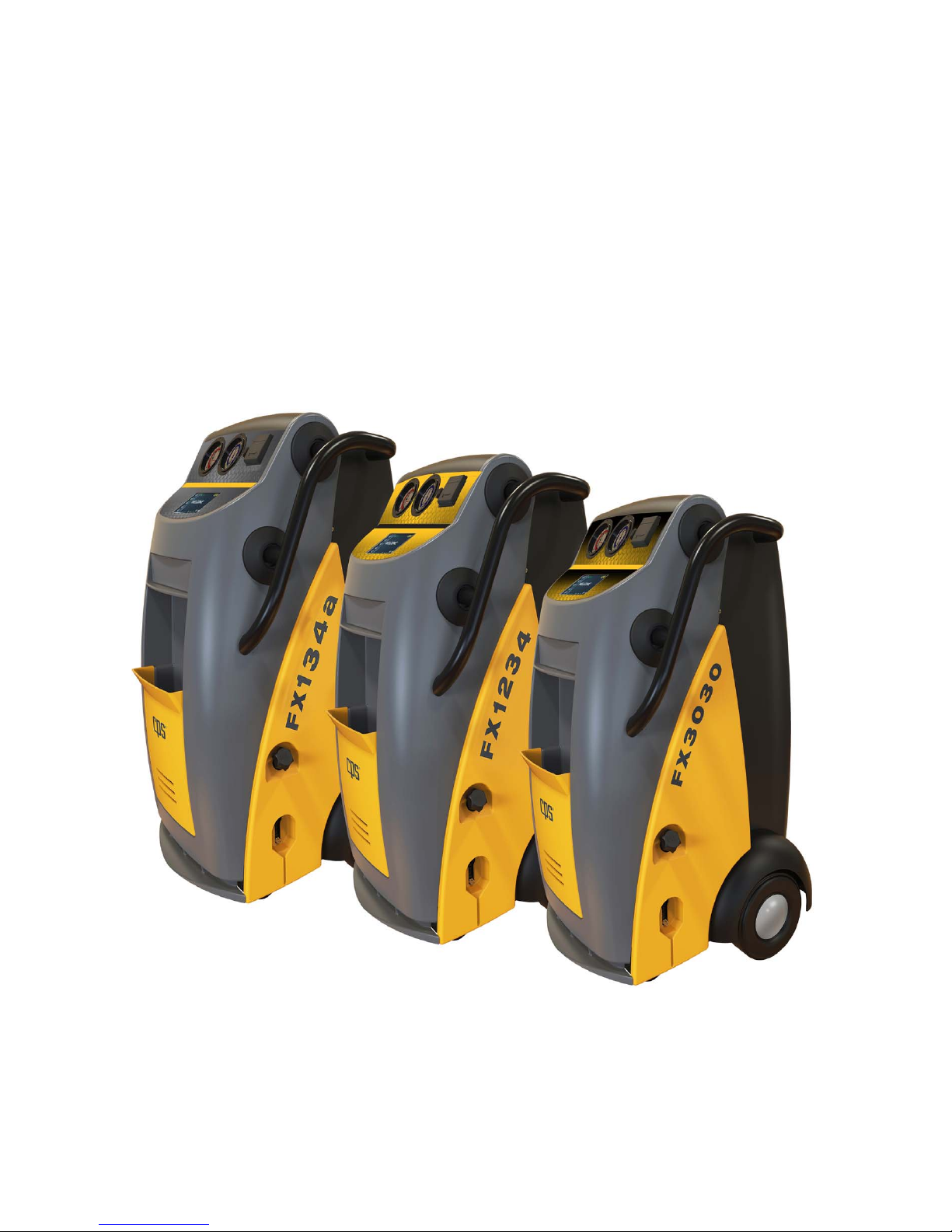
The FX series is a fully automatic Recovery/Recycling, and Recharging Refrigerant work station. The
FX134 Series meets and exceeds the new SAE J2788. FX1234 Series meets and exceeds the new
J2843/J2788. The FX3030 Series meets and exceeds J3030. The FX134, FX1234, and FX3030 Series
models are single circuit R/R/R machines for handling R134a, R1234yf from mobile AC systems. The
following table will give you more information on the models available, the power supply and the CPS
Automotive tank models available for the FX 134, FX1234, and FX3030 Series.
CAUTION: The FX134, FX1234, and FX3030 series uses the integrated scale for tanks overfill
protection. The information on Maximum Refrigerant and Empty Tank weights must be accurately
inputted or the overfill protection will not function correctly. See Warnings and Dangers of overfilling a
tank.
CPS Models Voltage Hz
FX134/FX1234/FX3030 115 50/60
FX134E/FX1234E/FX3030E 220-240 50/60
FX134J/FX1234J/FX3030J 100 50/60
CPS Tank Max Refrigerant Empty Tank
Models Weight Weight
CRX400T* 38 lbs. 0 ounces 28 lbs 8 ounces *
CRX390T 68 lbs. 0 ounces 57 lbs 8 ounces
40L 33.64 KG 20.9 KG
OTHER
1 The unit can be configured to most approved recovery tanks. Data from the tank manufacturer will be
required to complete the tank configuration process. See Section 1 for tank configuration details.
1 2 3
* comes standard on FX134/FX1234/FX3030
3

Many problems are a result of operator error. Please read the FX134/FX1234/FX3030 Series
operating manual. The manual is separated into 4 Sections:
Section 1 gives instructions on how to gain service access to the FX134/FX1234/FX3030. This Section
also gives instructions on proper calibration and mechanical repair procedure
Section 2 contains a list of common problems and how to resolve them.
Section 3 contains instructions on how to repair various components used in the
FX134/FX1234/FX3030Series.
Section 4 contains additional Electrical and Plumbing Schematics of the FX134/FX1234/FX3030Series.
This section also contains the FX134/FX1234/FX3030Series parts list.
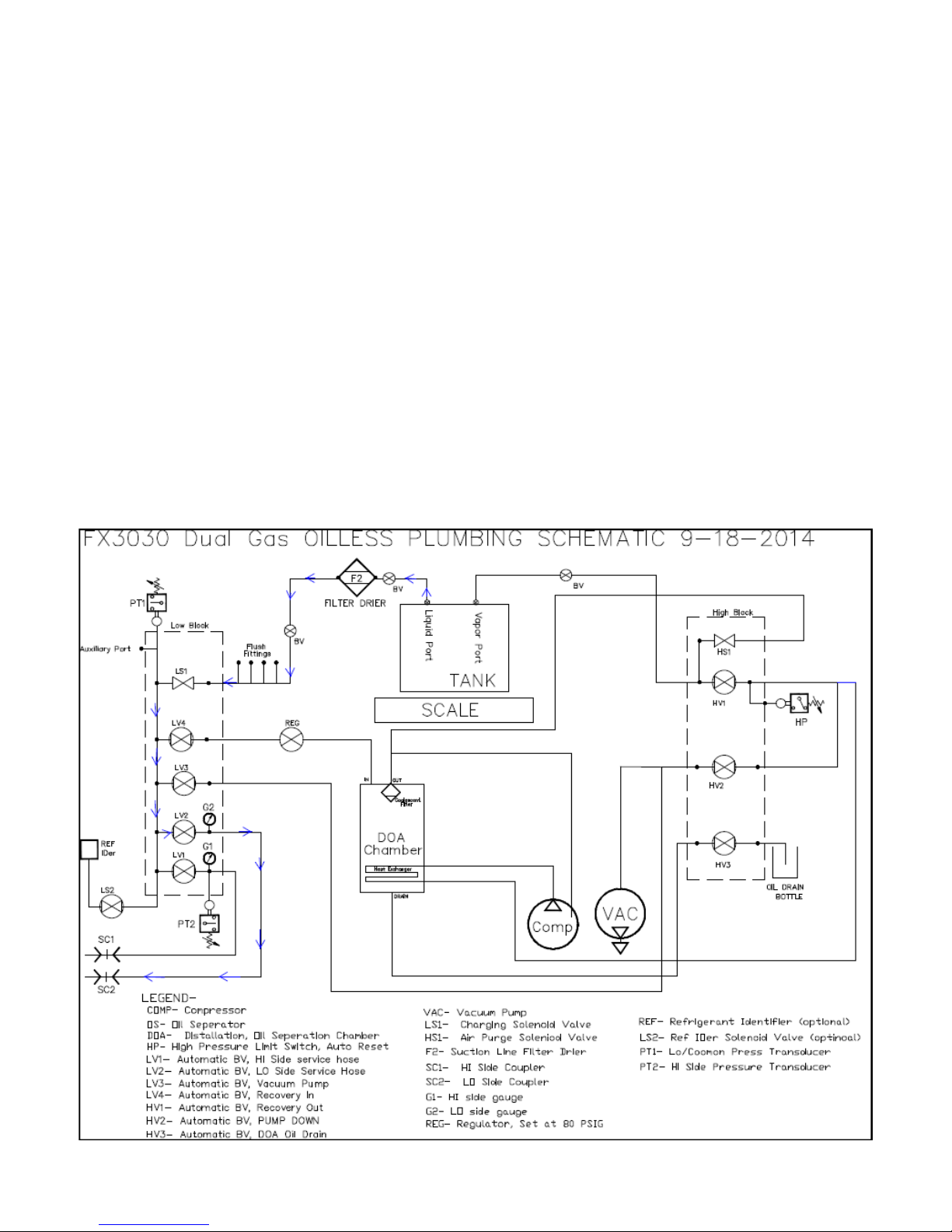
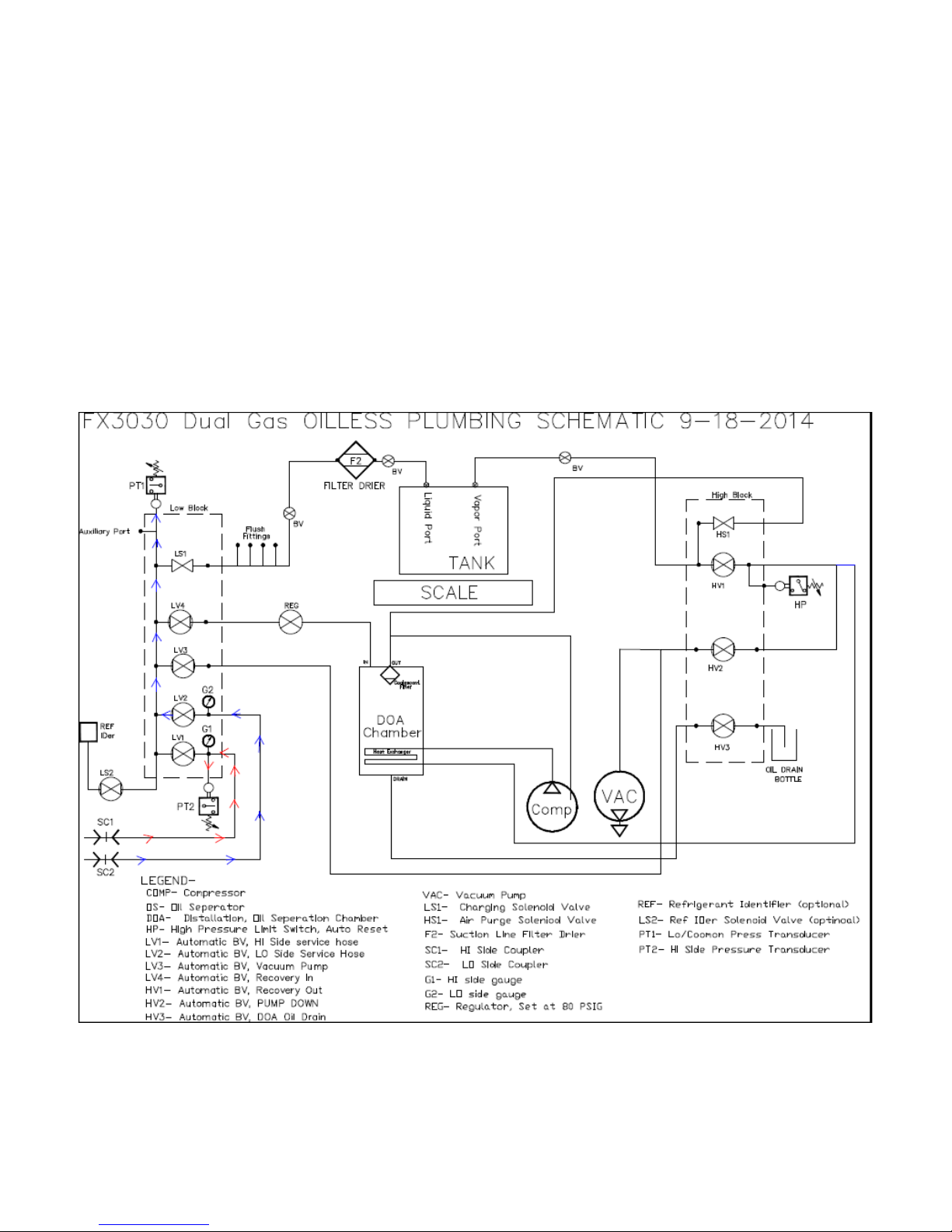
SUMMARY OF OPERATION
The following information will help illustrate the flow path of the FX134/FX1234/FX3030 series in each
of the unit’s modes. Understanding what valve, component, etc… that each mode utilizes will help with
faster diagnose and repair the unit.
4
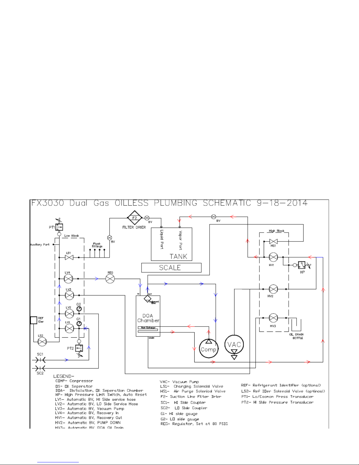
RECOVER/RECYCLE
NOTE: The FX1234 and FX3030 will implement refrigerant indentifying process according to J2743 . Refrigerant sample
will pass through (SC2) low side service hose. The refrigerant sample will then pass through low side manifold valve (LV2)
and (LS2) solenoid valve allow sample into identifier. Once refrigerant has been sampled and passes. The recovery unit will
operate as instructed below. See Identifier Plumbing Schematic.
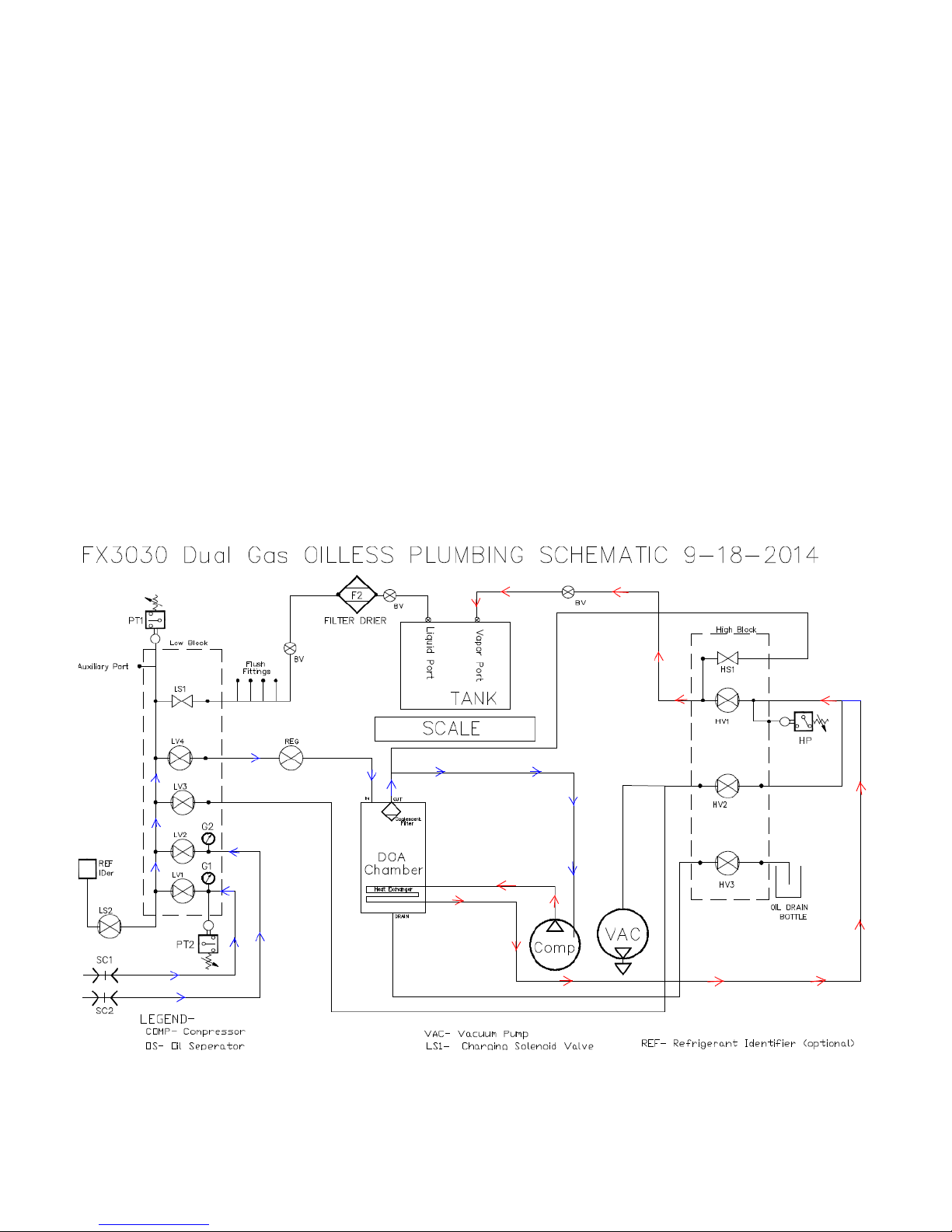
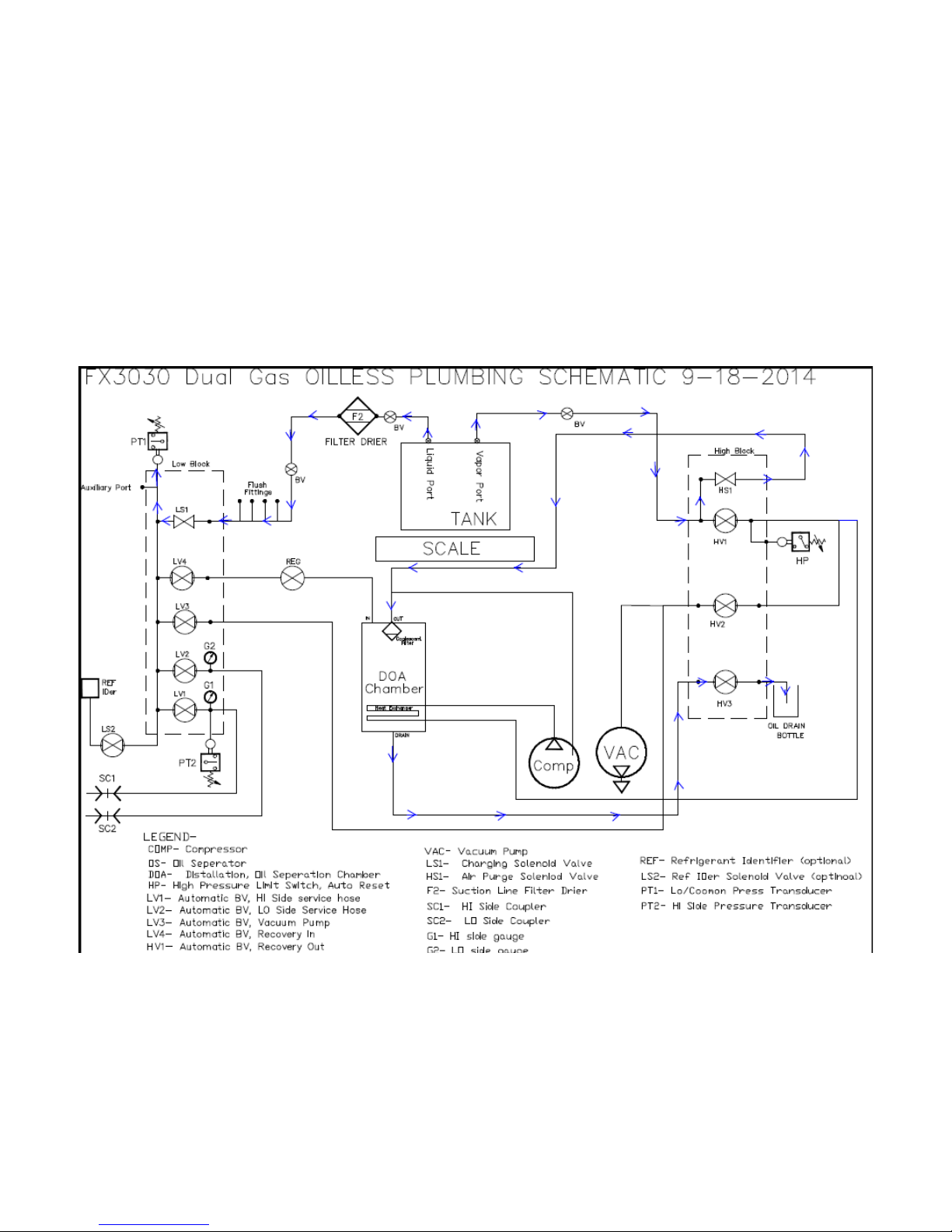
The Manifold gauges read the respective service line pressures. The recovered refrigerant will pass through their
respective open HI and LO manifold valves (LV1, LV2). The combined HI and LO refrigerant then flows through
the open RECOVER valve (LV4) and then into a Constant Pressure Regulator. The REGULATOR reduces the
pressure down to 80 psig where it flows into a DOA Chamber where oil is separated from refrigerant (if liquid is
present) the liquid refrigerant is boiled off by the heat exchanger in DOA Chamber. After leaving the DOA
Chamber, the vapor refrigerant enters the COMPRESSOR suction where it is compressed to a high pressure gas.
This completes the first step in the recycling process. The refrigerant then passes through the heat exchanger in
DOA Chamber then to RECOVERY OUT valve (HV1) and passes by the systems HIGH PRESSURE SWITCH
(HP) on its way to the storage tank. If the pressure goes above 450 psig, the HP will open and disrupt power to the
unit’s compressor and signals to the control PCB that a HIGH PRESSURE LIMIT condition exists. Recovery is
complete when the Pressure Transducer (PT) senses the required vacuum. When recovery is complete, the
automatic oil drain will commence for 45 seconds.
5
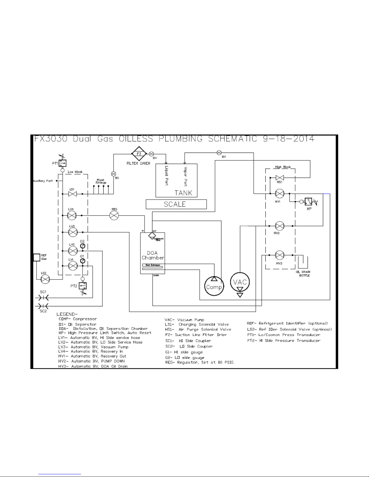
RECOVER- Oil Drain Flow
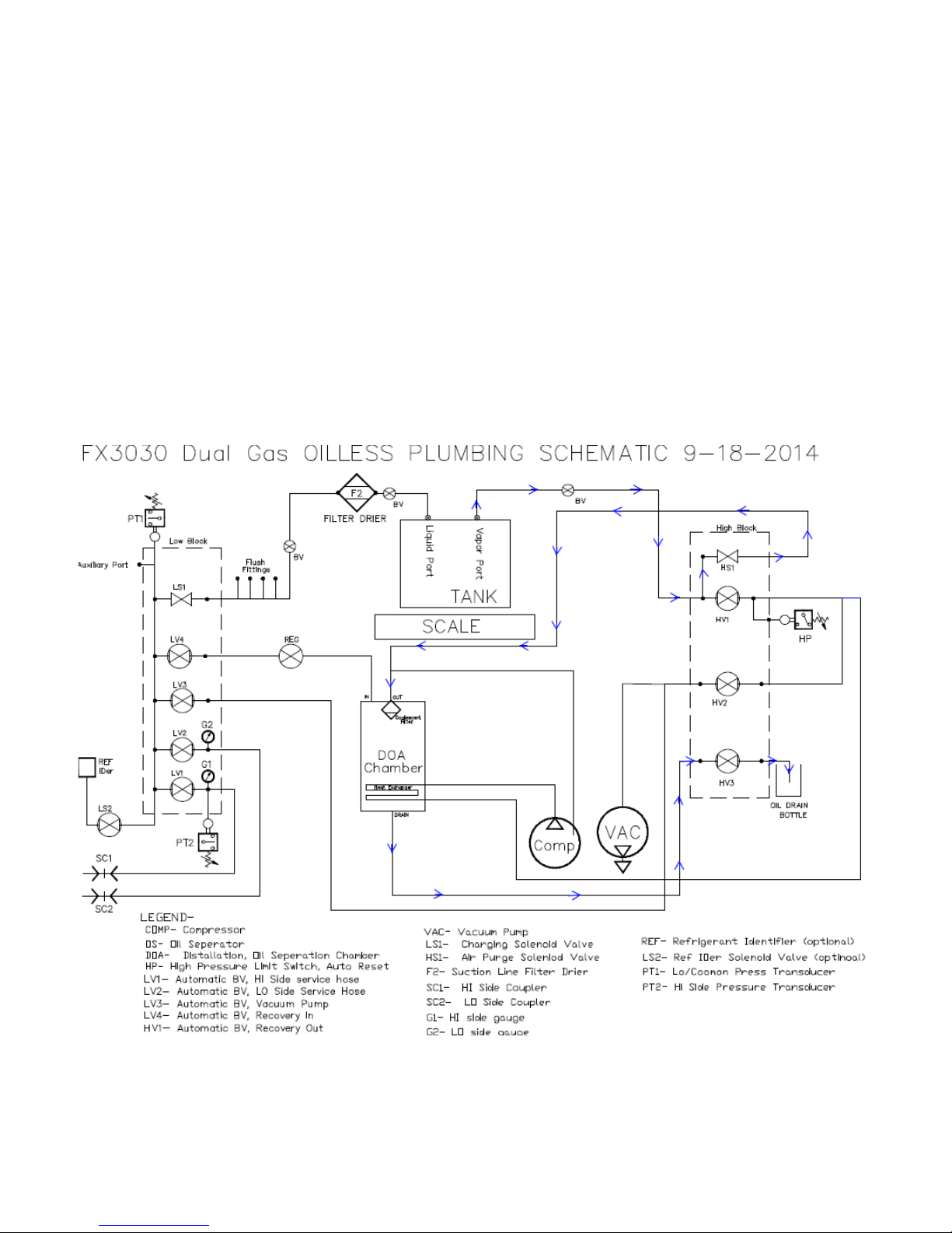
Once Recover is done and the compressor shuts off. The air purge valve HS1 will open to pressurize DOA
Chamber then HS1 will close. The compressor will come on to lower pressure in DOA for oil draining. Once
pressure level is achieved, then (HV3) opens allowing excess oil to drain from DOA Chamber for 30 seconds.
6
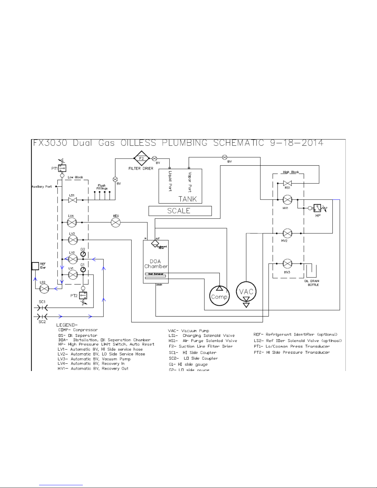
EVACUATION
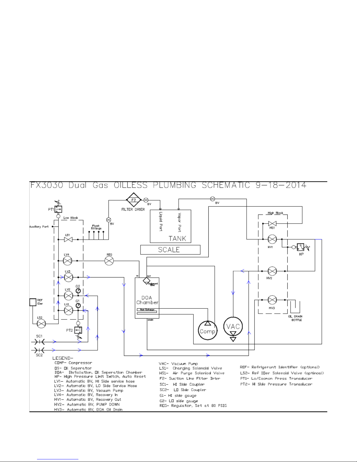
After the mobile a/c system is repaired, it should then be pulled into a deep vacuum to remove residual gasses and
moisture before recharging it with refrigerant. The unit evacuates gasses from the a/c system through the LO Side
and HI Side service hoses. The gasses enters the unit through the two service hoses attached to the LO and HI
Manifold. The gasses will then pass through their respective open LO and HI valves (LV1 and LV2). The combined
HI and LO gasses then flows through the open EVACUATION valve (LV3) and then into the VACUUM PUMP.
The VACUUM PUMP exhausts the evacuated gasses to the atmosphere.
IMPORTANT: if either the LO or HI manifold gauges read more than 5 psig, the unit will not start the evacuation
mode, but go into the RECOVER mode to recover the gasses causing the pressure.
The Evacuation mode will run per the programmed time set by the user.
7
CHARGE LOW SIDE
NOTE: FX1234 and FX3030 will have addition steps in charging according to J2743. There will be a 10 minute vacuum test.
The first 5 minutes the vacuum pump mode will run. (See Vacuum Plumbing Schematic) Then the second 5 minutes of the
vacuum leak test is where it checks for vacuum loss. Then a 15% of programmed charge is released for pressurizing A/C for
manual leak check using electronic leak detection. The unit will complete charge once all has passed as instructed below.
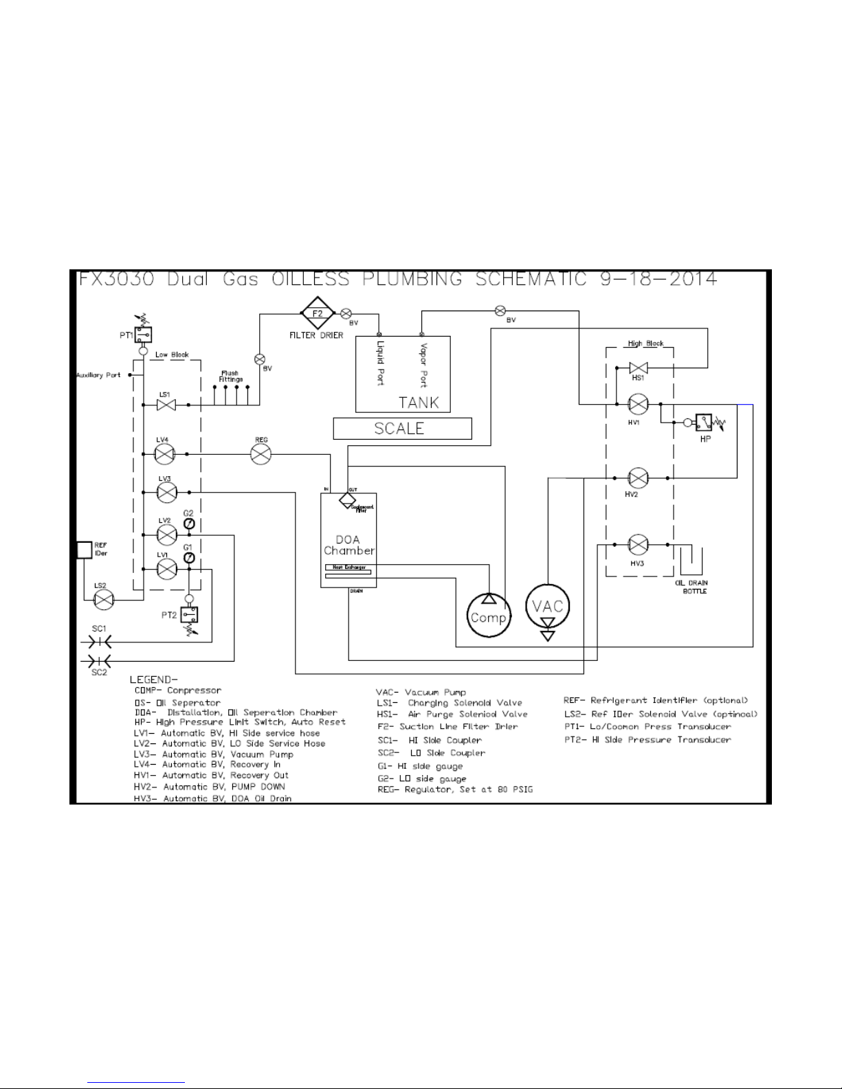
Using the keypad to program the desired charge, the liquid refrigerant from the storage tank will pass through the
FILTER DRIER (F2). This completes the third and final procedure of the recycling process. Once through the
FILTER DRIER (F2), the liquid refrigerant will then pass through the open CHARGING SOLENOID VALVE
(LS1). The liquid refrigerant will then pass through the open Low Manifold valve (LV2) and onward through the
Low service hose. After the required amount of refrigerant is charged, the control PCB de-energizes charging
solenoid valve (LS1). The LCD display charge complete, and ask if you want to go to Car Health. If you select to
use Car Health the screen will ask you to start car, and low side (LV2) will open and allow running pressures to be
seen at the pressure transducers. The screen will then display digital manifold and operating pressures on hi and low
side of A/C system. If you choose not use the Car Health, then the screen will ask you to close hi coupler and start
cars A/C system. The low and hi service hoses will then open (LV1 and LV2) and allow suction of car A/C
compressor to clear hoses.
8
CHARGE HI SIDE
NOTE: FX1234 and FX3030 will have addition steps in charging according to J2743. There will be a 10 minute vacuum test.
The first 5 minutes the vacuum pump mode will run. (See Vacuum Plumbing Schematic) Then the second 5 minutes of the
vacuum leak test is where it checks for vacuum loss. Then a 15% of programmed charge is released for pressurizing A/C for
manual leak check using electronic leak detection. The unit will complete charge once all has passed as instructed below.
The a/c system should be in a deep vacuum before proceeding. After using the keypad to program the desired
charge, the liquid refrigerant from the storage tank will pass through the FILTER DRIER (F2). This completes the
third and final procedure of the recycling process. Once through the FILTER DRIER (F2), the liquid refrigerant
will then pass through the open CHARGING SOLENOID VALVE (LS1). The liquid refrigerant will then pass
through the open HI Manifold valve (LV1) and onward through the HI, Lo, or both service hoses depending on
what was selected. After the required amount of refrigerant is charged, the control PCB de-energizes charging
solenoid valve (LS1). The LCD display will read “CHARGE COMPLETE” and give an audible signal.
9
CHARGE BOTH LOW AND HI SIDE
NOTE: FX1234 and FX3030 will have addition steps in charging according to J2743. There will be a 10 minute vacuum test.
The first 5 minutes the vacuum pump mode will run. (See Vacuum Plumbing Schematic) Then the second 5 minutes of the
vacuum leak test is where it checks for vacuum loss. Then a 15% of programmed charge is released for pressurizing A/C for
manual leak check using electronic leak detection. The unit will complete charge once all has passed as instructed below.
The a/c system should be in a deep vacuum before proceeding. After using the keypad to program the desired
charge, the liquid refrigerant from the storage tank will pass through the FILTER DRIER (F2). This completes the
third and final procedure of the recycling process. Once through the FILTER DRIER (F2), the liquid refrigerant
will then pass through the open CHARGING SOLENOID VALVE (LS1). The liquid refrigerant will then pass
through the open HI Manifold valve (LV1) and onward through the HI, Lo, or both service hoses depending on
what was selected. After the required amount of refrigerant is charged, the control PCB de-energizes charging
solenoid valve (LS1). The LCD display will read “CHARGE COMPLETE” and give an audible signal.
10
REFILL
NOTE: The FX1234 and FX3030 will implement refrigerant indentifying process according to J2743 . Refrigerant sample
will pass through (SC2) low side service hose. The refrigerant sample will then pass through low side manifold valve (LV2)
and (LS2) solenoid valve allow sample into identifier. Once refrigerant has been sampled and passes. The recovery unit will
operate as instructed below. See Identifier Plumbing Schematic.
To refill the FX134A / FX 1234 / FX3030, attach a new supply tank of refrigerant to the HI Side Service hose using
the required adaptors. The liquid refrigerant from the new refrigerant tank will flow through the open HI Side
service hose and pass through the open Hi Side valve (LV1) then through the open RECOVER valve (LV4) and
then into a Constant Pressure Regulator. The REGULATOR reduces the pressure down to 80 psig where it flows
into a DOA Chamber where liquid refrigerant is boiled off by heat exchanger in DOA chamber, and oil separated
from refrigerant. After leaving the DOA Chamber, the vapor refrigerant enters the COMPRESSOR suction where it
is compressed to a high pressure gas. The compressed refrigerant passes through the RECOVERY OUT valve
(HV1) then passes by systems HIGH PRESSURE SWITCH (HP) on its way to the storage tank. If the pressure
goes above 450 psig, HP will open and disrupt power to the unit’s compressor and signals to the control PCB that a
HIGH PRESSURE LIMIT condition exists.
11
AIR PURGE
Air Purge is performed automatically on the FX134A / FX 1234 / FX3030 series. Two thermistors are used to determine if the
storage tank have had enough time to stabilize. Once it is determine Air Purge can take place, the unit will open the charging
solenoid valve (LS1) to the Pressure transducer (PT). The PT compares this pressure to the actual saturated pressures stored in
the PCB microprocessor. If Air Purge is required, the Air Purge solenoid pressure.
12
REFRIGERANT IDENTIFIER 9(+,&/(6$03/,1*
The FX1234 and FX3030 will implement refrigerant indentifying process according to J2743. Refrigerant sample will pass
through (SC2) low side service hose. The refrigerant sample will then pass through low side manifold valve (LV2) and (LS2)
solenoid valve allow sample into identifier. Once refrigerant has been sampled and passes. The recovery unit will operate as
instructed below.
13
FX3030 PUMP DOWN
14
Hose Flush High Voltage Compressor
15
CAR HEALTH
Car Health the screen will ask you to start car, and low side (LV2) will open and allow low side running pressure to
be seen at the PT 1 pressure transducer. The hi side pressure will be seen at PT 2 pressure transducer which is
common to hi side service hose. The screen will then display digital manifold and operating pressures on hi and low
side of A/C system.
16
Section 1- Service Access and Calibration Procedure
1. Updating or Re-programming software
2. Front Service Panel Access
3. PCB Board/Control Panel Access
4. Scale/PC Board Recalibration Procedure
5. Tank Weight configuration
6. Scale Tare Procedure
7. Gauge Calibration Procedure
8. Pressure Transducer Recalibration
Note: If there is any question on how to perform these procedures, please consult CPS service
center.
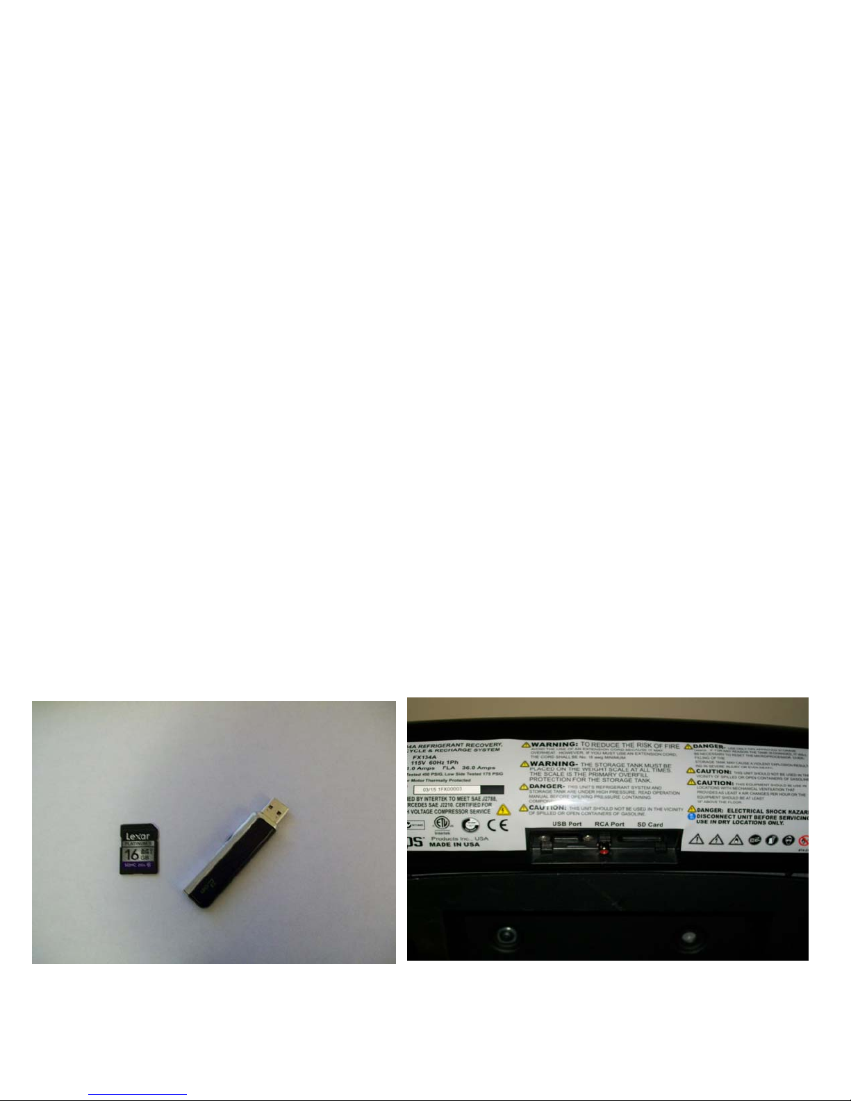
1. Updating Program
a. The unit can be updated by using USB stick or SD card.
b. The SD card is simply inserted to the SD reader on the back of control panel and turn on unit. The unit will
beep three times at the start of installation, and then single beeps as it loads program. The unit will beep
three times at the end if down load. No password is needed. Do not remove SD card unit main screen “Do
Not Connect to Car” comes up.
c. The USB is used from the update date screen. On the home screen push the gear icon on bottom of screen.
Two new icons will appear. Select the wrenches on right side of the screen. Then six new icons will appear.
Select the Up grade icon and install USB stick into USB Port. The screen will detect program and then push
green arrow and will prom you for password that came with update.
17
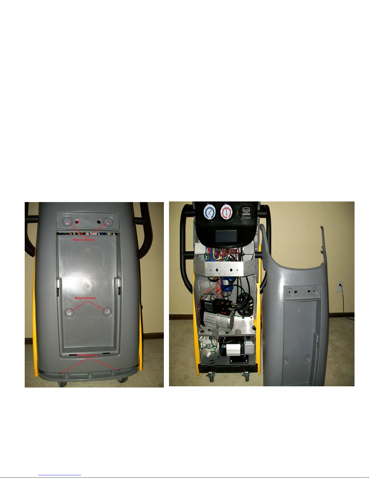
2. Front Panel Service Access into FX134A / FX1234 / FX3030
a. Remove service hoses, oil drain bottle, yellow holding bin for accessories and yellow face plate to expose panel
screws.
b. Remove screws as indicated in picture and remove front panel.
panel outer edge at very top on control panel. Remove screws if unit has them.
Note: Check for screws on side cover over lapping top
c. Removing the front access panel gives access to the lower section of the unit where the DOA, Fan, Condenser,
Evaporator, Regulator, Compressor, Vacuum Pump, Power Supply PCB’s, Pressure Transducer PCB, and Relay PCB
are contained.
18
 Loading...