

CPS FA1000 SERIES, FA1000A, FA1000, FA1000B, FA1000AB Operation Manual
...
FA1000 SERIES REFRIGERANT RECOVER
/ RECYCLE / EVACUATION AND RECHARGE UNIT
Unit covered under US Patent
8,082,750 and other patents
pending.
Certied by ITS under SAE
J2911 to meet SAE J2788 for
R-134a.
Certied by ITS under SAE
J2911 to meet high voltage
compressor service per SAE
2788 for R-134a.
OPERATION MANUAL
Models: FA1000, FA1000A, FA1000B FA1000AB, FA1000E, FA1000J
Unit Consists Of:
• FA1000 Series Mach 7 Automotive Refrigerant Recover / Recycling / and Recharge Machine
• 6 CFM 50 micron vacuum pump
• Recovery Cylinder - FA1000 and FA1000J inclued a 50 lb DOT storage tank, FA1000B and FA1000AB include 92 lb storage tank
FA1000E does not include storage tanks. User must use country approved storage tanks
• Low and High side service hoses for R-134a
• Low and High side R-134a couplers
• Tank rell adapter, 1/2" ACME RH Female for R-134a
• 41 cubic Inch CPS lter drier (Replacement part number ARXF5)
• Tank lter bracket with hardware and all tank hoses if the tank is not included
• 1 lb (454 gram) check weight
• Operation manual
• Models FA1000/FA1000B come with UView 481500 Oil/Dye Injection Kit, All other models come with integrated Oil Injection System
End user to provide:
• R-134a
• Refrigerant oil and/or dye for injection system
Table of Contents
Specications 2
Introduction 3
General Safety Instructions 4
Initial Equipment Preparation 5
Initial Set-Up 6
Operating Instructions 7-16
Maintenance 17-20
High Voltage Charging, Hose Maintenance and Troubleshooting Chart 21
Service Parts and Accessories 22-23
Warranty and Contact Information 23
FA1000 Specications
Models FA1000 / FA1000B FA1000J FA1000A / FA1000AB FA1000E
Compressor Type 2/3 HP, 2 cylinder oil-less reciprocating compressor
Dimensions 22" W x 24.5" D x 42" H
Weight
Operating Range 10˚C (50˚F) to 49˚C (120˚F)
Power Source 115 VAC 60Hz 1Ph 100 VAC 50 / 60Hz 1Ph 220-240 VAC 50Hz 1Ph 220-240 VAC 50Hz 1Ph
Power Consumption 1000 W
Low Side Gauge -30 inch Hg to 125 PSIG
High Side Gauge 0 to 500 PSIG
Filtration 41 cubic inch drier, .7 micron oil separator
Automatic Control Valves Patented motorized ball valves to control HI, LO, recover, and vacuum
Charging Valve 12 VDC Solenoid Valve
Construction
Overload Protection 15A Thermal Breaker 15A Thermal Breaker 10A Thermal Breaker 10A Thermal Breaker
High Pressure Shut-O 30 bar (450 psig)
Refrigerants
100 lbs (does not include tank weight)
1" Heavy duty tubular frame construction
10" pneumatic wheels, 4" swivel casters
R-134a
2

INTRODUCTION
Thank you for purchasing the
by the USEPA. In accomplishing this goal, CPS has integrated its latest patent pending technology and incorporated state of the art features
while improving relaibility and performance. The unit also meets the SAE standards for High Voltage Compressor service.
The FA1000 automatically recovers, recycles, evacuates, and recharges mobile A/C systems. Simply hook up the service hoses, choose the
desired operation, and allow the unit to automatically complete the A/C service.
The FA1000 utilizes a single pass (oil coalescing, particle ltration, and moisture removal) recycling system, which means that whenever the
FA1000 recovers, it also recycles. The unit also incorporates automatic air purge to remove unwanted non-condensable gasses from the
refrigerant. Thus the refrigerant storage tank always contains the cleanest refrigerant possible for future recharge use.
The FA1000 utilizes CPS’s patented motorized ball valves. The motorized ball valves are unique to the industry in that they will not be aected
by sealants, particulates, and other contaminates. The motorized ball valves incorporate passage ways 8-15 times larger than the existing
solenoid valves orice technology. In fact the FA1000 uses no solenoid or check valves in the active ow path during recovery or evacuation,
thus enhancing speed.
The FA1000 utilizes CPS’s patent pending two cylinder oil-less compressor. This compressor improves reliability and performance. Being oil
free, no compressor oil maintenance or oil return system is required.
The following are additional features:
• Integrated manifold gauge set. Visually see how the mobile A/C system is operating. No manual valves to open of close
• Large Graphic LCD to view operating instructions. Languages include English, Spanish, French, German, Chinese and more
• A highly accurate electronic charge scale
• Microprocessor Integrated mass ow system keeps track of how much refrigerant has run through the lter drier giving the user maxi-
mum amount of run time on each lter (150 LBS per lter)
• Cartridge type 41 inch cubic lter drier. Mounted directly on the storage cylinder for optimal moisture removal and weight accuracy
• Automatic high-pressure shut-o with microprocessor indication
• Interchangeable CPS Recovery cylinders. Use your country’s approved refrigerant cylinders. The software allows the user to set up the
proper tank and refrigerant parameters. Larger cylinders, such as CPS CRX390T, can be used for larger truck and bus A/C systems
• Modular design for easy replacement of a defective plumbing, scale, electronic, compressor or vacuum pump sub system
• Heavy-duty construction: Powder coated steel cabinet mounted onto a 1" tubular steel frame
• 10" pneumatic rear wheels and 4" swivel casters give this unit excellent maneuverability under the worst of conditions
• Recovers and Evacuates through both the high and low side service hoses
• Separate Vacuum pump for faster evacuations
• Additional service hose lengths available, 8 foot comes standard
• Programmed electrical outlet for optional heater blanket installation
• Oil injection on either or both the High and Low side
• Refrigerant charging on either or both High and Low side
• Approved for High Voltage (Hybrid) AC systems. Equipped with Hybrid hose ush block to clear service hoses of residual oil
CPS FA1000
series unit. The FA1000 has been designed to meet SAE J2788 and J2911 standards as required
To help you get a good start, please continue to carefully read the balance of this manual. This manual contains important information on
the proper procedures for operating this equipment. Please pay close attention to the safety information, Warnings, and Cautions provided
throughout this manual. Always remember “Safety First”.
Certied by Intertek under SAE J2911 to meet SAE J2788 standard for R-134a and the SAE J2788 High Voltage Compressor service provision.
3

GENERAL SAFETY INSTRUCTIONS
Only qualied service personnel should operate this unit. Most states, countries, etc… may require the user to be licensed. Please check with
your local government agency.
DANGER-
injury or even death. Do not disable the overll safety features. Always make sure the correct tank is on the scale.
DANGER-
DANGER-
loss of consciousness, or even cause suocation.
DANGER- Electrical shock hazard!!!!
DANGER- DO NOT USE COMPRESSED AIR TO PRESSURE TEST OR LEAK TEST THE UNIT OR VEHICLE AIR
CONDITIONING SYSTEM.
dangerous and may result in re or explosion causing personal injury or property damage.
CAUTION-
proper personal protective equipment such as safety goggles and gloves. When disconnecting any hose, please use extreme caution.
CAUTION-
manufacturers Material Safety Data Sheet for further safety information on refrigerants and lubricants.
CAUTION-
table references extension cord wire size vs. maximum length:
this unit’s recovery tanks contains liquid refrigerant. Overlling of a recovery tank may cause a violent explosion resulting in severe
Only use the recovery tanks provided with this unit. See distributor for replacement tanks.
Avoid breathing refrigerant vapors and lubricant vapor or mist. Breathing high concentration levels may cause heart arrhythmia,
Always disconnect power source when servicing this equipment.
Some mixtures of air and R-134a refrigerant are combustible at elevated pressures. These mixtures are potentially
all hoses may contain liquid refrigerant under pressure. Contact with refrigerant may cause frostbite or other related injuries. Wear
avoid breathing refrigerant vapors and/or lubricant mist. Exposure may irritate eyes, nose, throat, and skin. Please read the
to reduce the risk of re, avoid the use of extension cords thinner than NO. 16 awg. (1,5mm²). The following
WIRE GAUGE MAXIMUM LENGTH
14 25
12 50
CAUTION-
all safety devices are functioning properly before operating the equipment.
CAUTION-
CAUTION- RISK OF INJURY
CAUTION-
required and have direct aect on the proper operation of this equipment.
do not use this equipment in the vicinity of spilled or open containers of gasoline or other ammable substances. Make certain that
This equipment should be used in locations with mechanical ventilation that provides as least 4 air changes per hour.
, the equipment should only be operated by certied personnel.
Use only CPS certied hose assemblies on this unit. The hose assemblies are made to proper length, contain shut os where
16 10
(feet)
4
INITIAL EQUIPMENT PREPARATION
Models FA1000, FA1000A and FA1000J
Will come with a 50 lb DOT tank and lter assembly pre-mounted on the
rear of the machine. Please follow the instructions for initial
equipment preparation:
1. Carefully unpack the unit and its contents from its
shipping pallet.
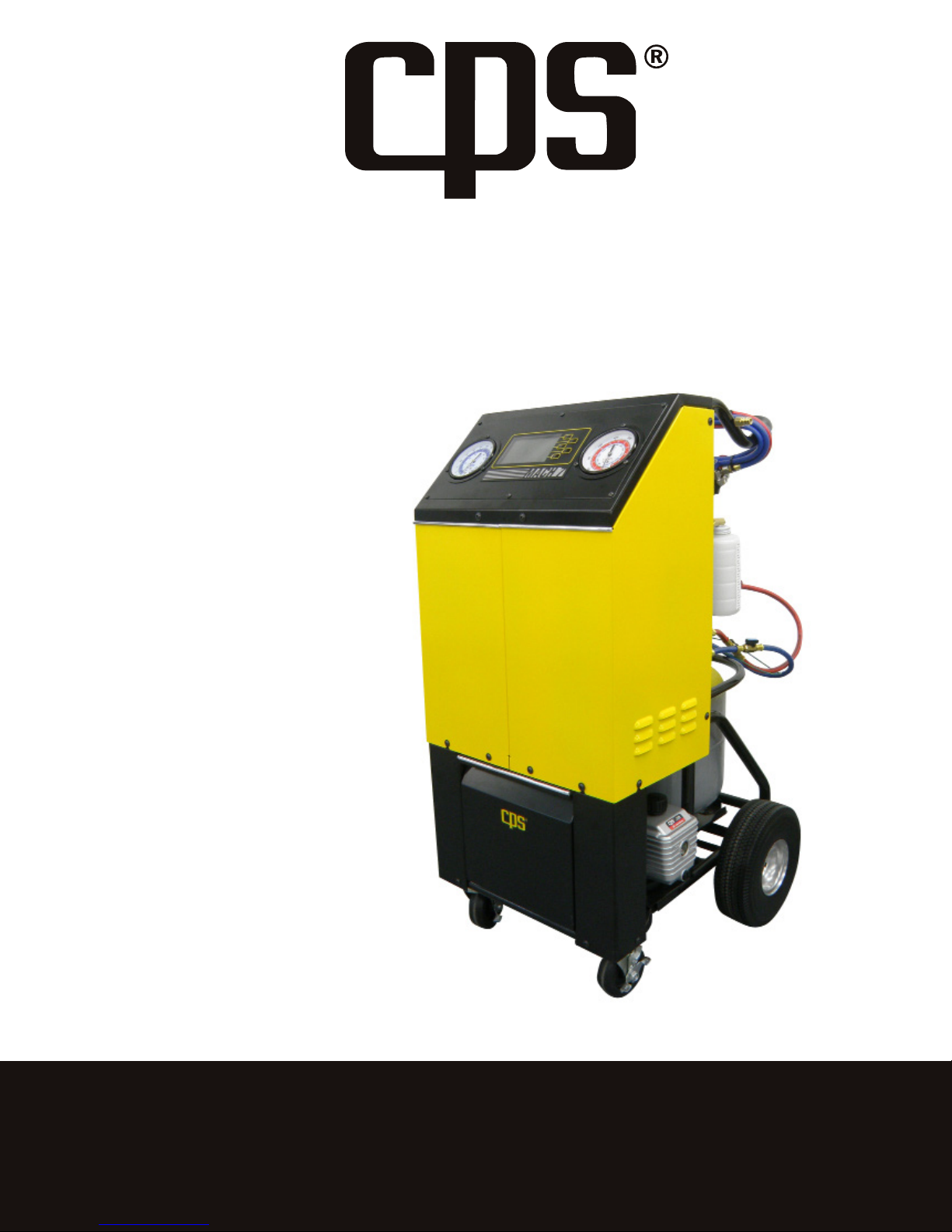
2. Remove the Styrofoam insert from below the tank and cut
the shipping band from around the tank.
3. Ensure all hose connections are rmly hand tight as they may have
come loose during shipping.
The contents of the accessory box are as follows:
1 Power cord
2 R-134a rell hoses, 1/4" SAE and 1/2" ACME
1 1 lb check weight
1 R-134a ID tank label
For the FA1000E the following will be included in the tank accessory
box.
1 Filter, lter bracket, Velcro and tie straps
1 Yellow liquid tank to lter hose
For models FA1000, FA1000A and FA1000J go to page 6.
The following are instructions to mount the lter assembly and lter hose
onto a self provided recover tank for models FA1000E. Place the tank on
the center of the scale (Make sure the tank is free standing).
FIGURE - 1 Shipping bracket
a
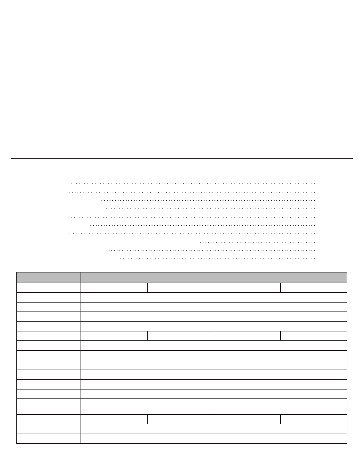
FIGURE - 2a Filter bracket placed
on tank collar
a
b
1. Install the lter bracket on the recovery tank as shown in
Figure - 2a. Secure the lter bracket to the tank collar using the
supplied tie straps. Cut o the excess tie strap after fully
tightening.
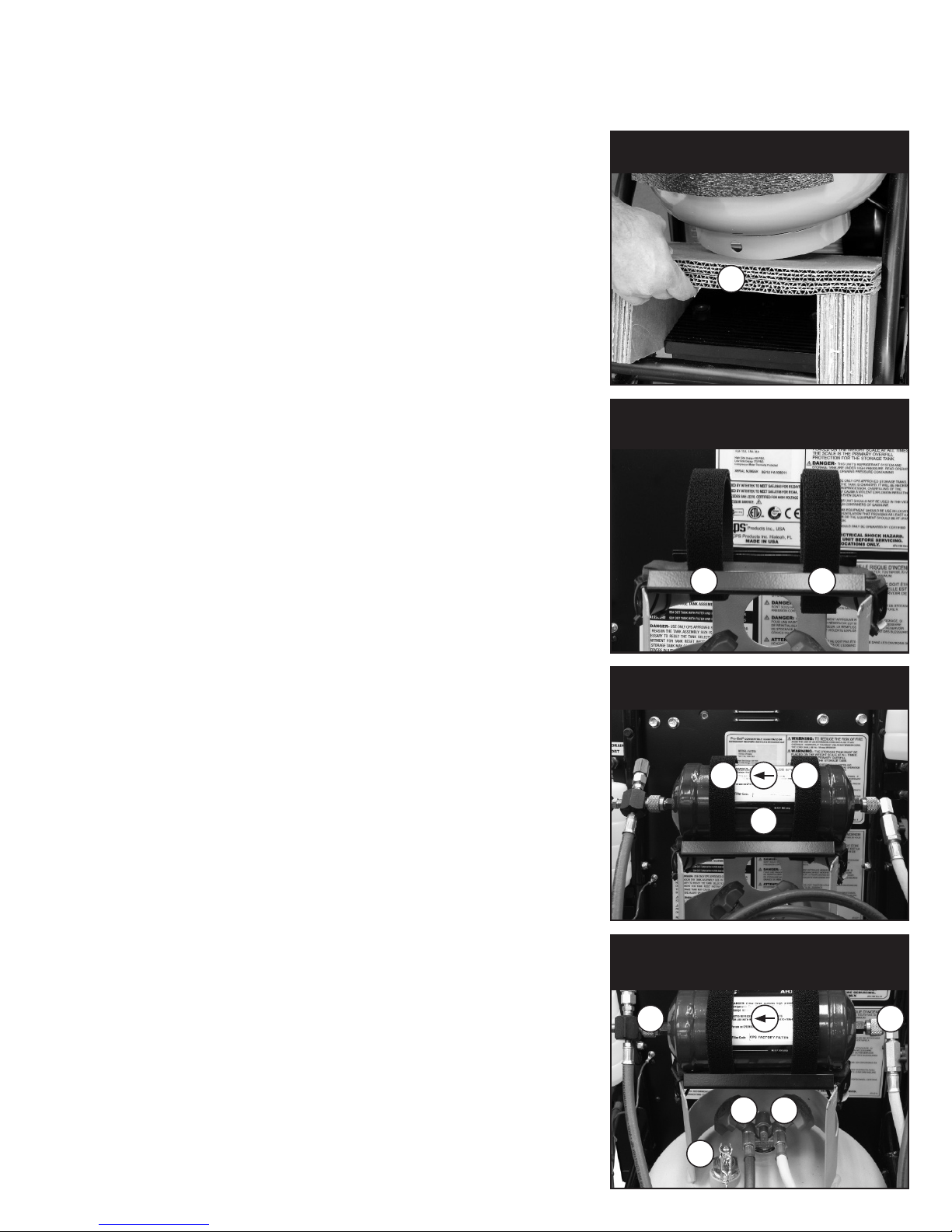
2. Secure the lter to the bracket using the supplied Velcro
straps making sure the arrow on the lter is pointing to the
left as illustrated in Figure - 2b.
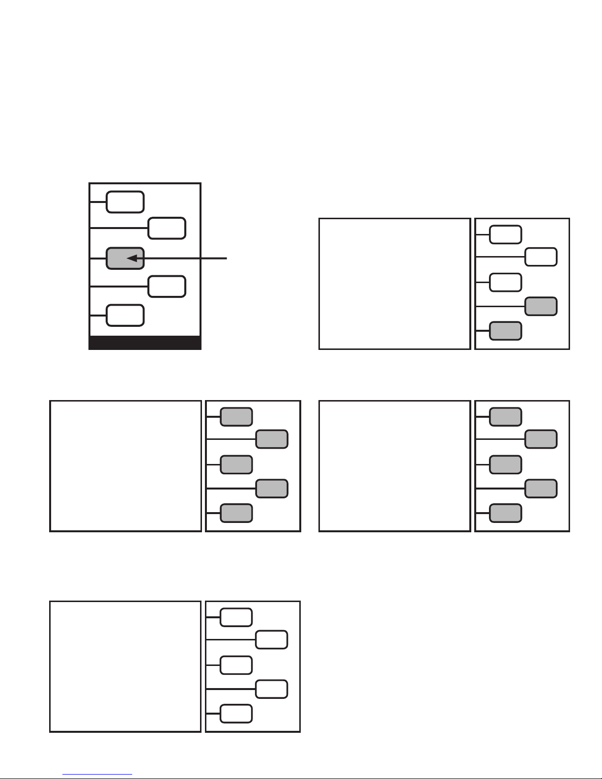
3. Install the refrigerant tank and lter hoses as shown in Figure - 2c.
Connect the yellow liquid feed hose/hybrid adapter which comes
from the machine to the lter port (a). Connect the yellow tank
liquid hose from the tank liquid port (d) to the lter port (b).
Connect the blue discharge hose coming from the machine to the
vapor port (c) on the tank. Finally connect the ground wire to the
tank as shown in Figure - 2c. If there is not a brass tting on your
particular tank, any unpainted surface on the tank itself will do.
FIGURE - 2b Filter placed on lter bracket
a
a
b
FIGURE - 2c Hose routing between lter,
tank, and unit
a
c
d
b
e
5
FA1000 INITIAL SET-UP
The following instructions will guide you through the initial set up fo the unit that allows changes to operational software, language and units of
measure.
Before we power up the unit, it will be necessary to check the vacuum pump oil sight glass for the correct level. The vacuum pump is pre-lled
at the factory. Make sure the vacuum pump power switch is in the ON position. Also check the hose connecting to the vacuum pump is tight.
Make sure both Oil Injection (if equipped) and Oil Drain bottle assemblies are tight. Make sure the Oil Injection (if equipped) valve is in the
position.
Open all tank and hose valves on the back of the unit.
Plug the unit into the proper voltage power supply. Check the nameplate of the unit if there are any questions on power supply requirements.
While holding down the
Key #3
, push the momentary ON-OFF switch on the back of the unit until the LCD lights up.
OFF
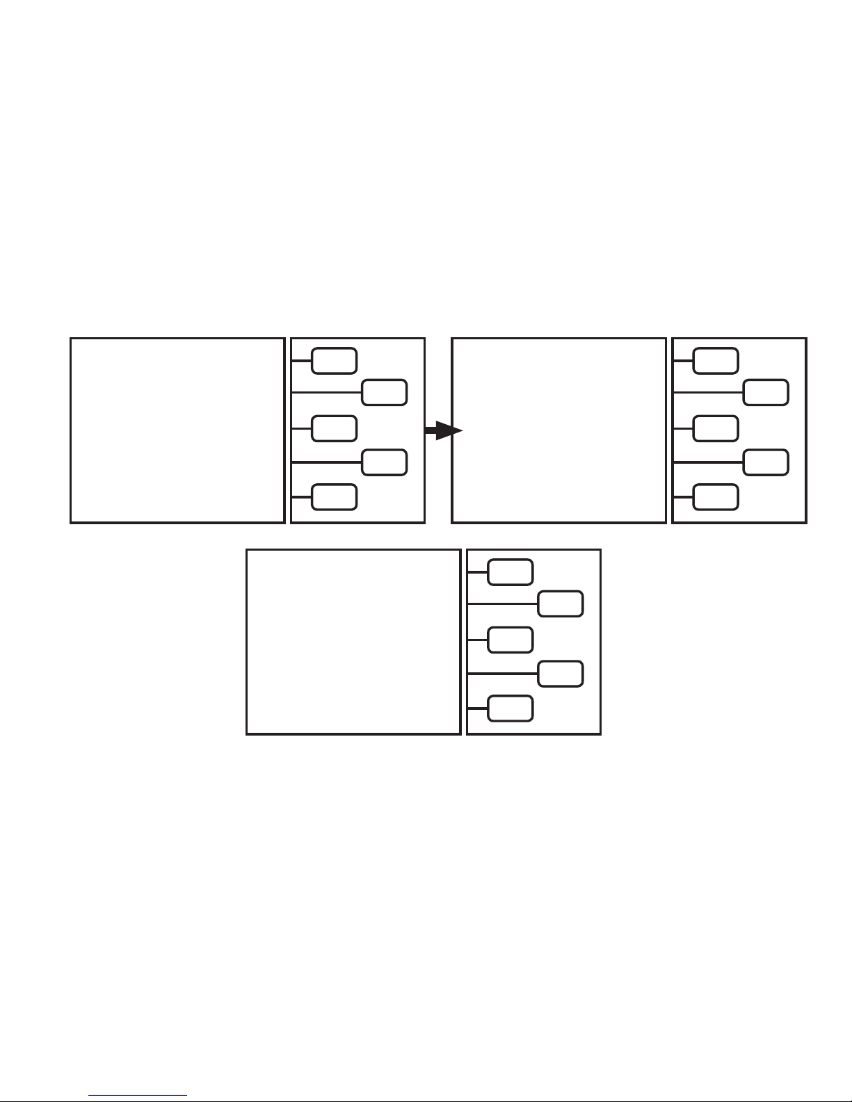
The LCD comes up with
SETUP MODE
screen asking for SAE
or NON-USA.
SETUP MODE
Key 3
SAE >
NON-USA >
FIGURE - 5
SAE applies to USA use. NON-USA would be used for anywhere outside of the USA. Keep in mind the operation of the unit is slightly dierent
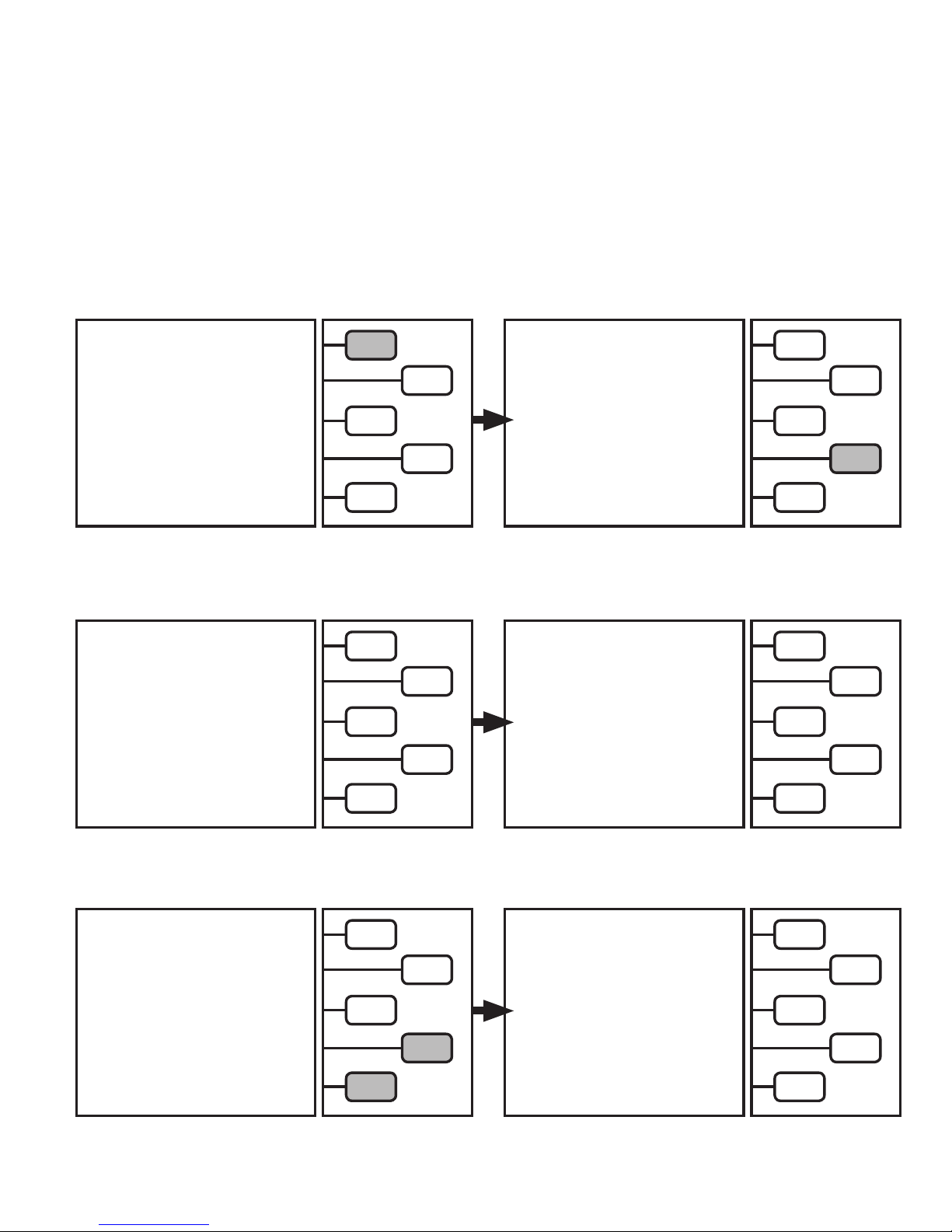
depending on which mode you use. Push either the
ENGLISH >
ESPAÑOL >
SELECT DEFAULT
LANGUAGE
DEUTSCH >
FRANCOIS >
SAE or NON-USA
key for selection. Now the laguage selection screen comes up.
LBS >
LBS : OZ >
SELECT DEFAULT
UNITS OF
WEIGHT
KGS >
GRAMS >
NEXT >
Push the key next to the desired language. The LCD will now show
you are most likely to use.
Note: That during any Charge or Full Cycle operation, the UNIT OF WEIGHT can be temporarily changed.
SELECT DEFAULT UNITS OF WEIGHT.
OZ >
Push the weight measurement system
The unit will proceed to the automatic PT (Pressure Transducer) calibration and then (if required) the air purge. This should only take
minutes and once complete the
RECOVER >
EVACUATE >
MAIN MENU
will appear on the LCD.
FA1000 is now ready for R-134a operation.
Place the R-134a ID tank label on the storage tank. Then go to
SELECT MODE
CHARGE >
FULL CYCLE >
TANK REFILL >
page 18 to ll the recovery tank with R-134a.
6
a few
OPERATING INSTRUCTIONS FOR THE FA1000
IMPORTANT: BEFORE USING THIS START UP GUIDE IT IS HIGHLY RECOMMENDED THAT THE USER COMPLETELY READ AND
UNDERSTAND THIS ENTIRE MANUAL. FAILURE TO OPERATE AS SPECIFIED COULD RESULT IN DAMAGE TO THE UNIT, WHICH COULD ALSO
LEAD TO LOSS OF WARRANTY.
The FA1000 is a microprocessor driven unit. The operating instructions are contained on the LCD. Simply choose the
desired function of the unit and follow the directions on the LCD. The following are the basic instructions on safely
operating each function of this unit.
Operating Instructions
Open all Storage Tank Valves. Make sure both Oil Injection (if equipped) and Oil Drain bottle assemblies are tight. Make sure the Oil Injection
(if equipped) valve is in the OFF position. Push the momentry Power switch to (ON). The unit will run a brief diagnostic routine.
LCD will read:
air purge sequence. This will take up to 3 minutes.
RE-Zeroing PT, Please wait.
Once done with PT calibration process, the unit will proceed to the automatic
RE-ZEROING
P. TRANSDUCER
PLEASE WAIT
The LCD screen should now read:
This is called the
MAIN MENU.
SELECT MODE
RECOVER >
EVACUATE >
CHARGE >
*FULL CYCLE >
TANK REFILL >
AUTOMATIC AIR PURGE
• Connect the refrigerant service hoses to the automobile A/C system to be serviced.
• Open the High and Low side service couplers.
PLEASE WAIT
Push the
KEY
for the desired mode.
The different modes are as follows:
1. Recover
2. Evacuation (Vacuum)
3. Charge
4. Full cycle
5. Tank rell
Follow the directions on the LCD for each mode. The following pages will discuss the operation of each mode in detail.
7
OPERATING INSTRUCTIONS FOR THE FA1000
RECOVER MODE: The Recover/Recycle mode would be chosen to recovery refrigerant from an Auto A/C system that
needs a refrigerant containing component replaced such as a compressor, evaporator, orice tube, condenser, etc….
IMPORTANT: Before starting the recover of the refrigerant, a refrigerant identier should be used to to determine the type and purity
of the refrigerant. Failure to properly identify the refrigerant could potentially expose the user to danger from ammable refrigerants
and health hazards from toxic refrigerants. Cross contamination of refrigerants can also occur and would require special handling of
the refrigerant.
From the Main Menu screen,
Push the
RECOVER
SELECT MODE
key.
RECOVER >
EVACUATE >
CHARGE >
FULL CYCLE >
TANK REFILL >
The LCD will now read:
The unit is now recovering refrigerant.
The LCD will show the amount of refrigerant recovered.
RECOVERY IN PROGRESS, PLEASE
WAIT
RECOVERED
1.00 LBS
TANK CAPACITY
REMAINING
25.00 LBS
QUIT >
The LCD will now read:
Push the
START
key.
MAKE CERTAIN HOSES ARE
CONNECTED AND VALVES ARE
OPENED. THEN PRESS [START]
*TANK CAPACITY
REMAINING
START >
26.00 LBS
QUIT >
When the unit reaches approximately 20" hg. vacuum.
The LCD will now read.
The unit will proceed to drain the recovered oil:
RECOVERY COMPLETE
RECOVERED
2.00 LBS
DRAINING OIL
00:00:45
PLEASE WAIT
QUIT >
Record the
EVACUATE
RECOVERED
weight reading on the LCD. Push the
key for evacuation operation. Do not forget to measure the A/C oil in the oil drain bottle for future A/C oil re-injection.
RECOVER/RECYCLE Operation is now complete.
RECOVERY COMPLETE
RECOVERED
2.00 LBS
TO VACUUM >
QUIT >
*
TANK CAPACITY REMAINING - is the amount of space available in storage tank.
QUIT
key to return to
8
MAIN MENU
SELECT MODE
(as shown below) or
RECOVER >
EVACUATE >
CHARGE >
FULL CYCLE >
TANK REFILL >
PROCEED TO
 Loading...