


1
C Prox Ltd (inc Quantek)
59 Sheffield Road, Dronfield, S18 2GF
+44(0)1246 417113 sales@cproxltd.com www.quantek.co.uk
Keypad & Reader Access Control
DPN-2
User Manual
Contents
1. Packing List ................................................................................................................................................. 2
2. Description .................................................................................................................................................. 2
3. Features ...................................................................................................................................................... 2
4. Specification ............................................................................................................................................... 3
5. Installation .................................................................................................................................................. 3
6. Wiring ......................................................................................................................................................... 3
7. Sound and light indication .......................................................................................................................... 4
8. Quick programming guide .......................................................................................................................... 4
8.1 Administrator settings (master code, manager cards, anti-duress, etc) ......................................... 4
8.2 User setting for Zone 1 (add/delete users, door opening mode, relay time, etc) .......................... 4
8.3 User setting for Zone 2 (add/delete users, door opening mode, relay time, etc) ......................... 5
8.4 System settings (working mode, facility code, Wiegand format, transmission code, etc) ............. 5
8.5 User optional settings (keypad tone, backlight mode, LED mode, etc) .......................................... 5
9. Full programming guide.............................................................................................................................. 6
Programming advice ................................................................................................................................... 6
9.1 Administrator settings (master code, manager cards, anti-duress, etc) ......................................... 6
9.2 User Settings for Zone 1 (add/delete users, door opening mode, relay time, etc) ........................ 7
9.3 User Settings for Zone 2 (add/delete users, door opening mode, relay time, etc) ........................ 8
9.4 System settings (working mode, facility code, Wiegand format, transmission code, etc) ............. 8
9.5 User optional settings (keypad tone, backlight mode, LED mode, etc) .......................................... 9
10. User operation ...................................................................................................................................... 10
11. Alarm functions ..................................................................................................................................... 10
12. Multi working modes (information and setup) .................................................................................... 10
12.1 Wiegand reader mode ................................................................................................................... 10
12.2 Standalone for single door ............................................................................................................ 11
12.3 Standalone for two doors .............................................................................................................. 11
12.4 With external reader for two doors .............................................................................................. 11
12.5 Two units interlocked for two doors ............................................................................................. 11
12.6 Anti-passback for single door ........................................................................................................ 12
12.7 Anti-passback for two doors .......................................................................................................... 12
13. Wiring diagrams for all 7 multi working modes.................................................................................... 12
14. Troubleshooting .................................................................................................................................... 15
15. Reset to factory default ........................................................................................................................ 15
16. Issue record ........................................................................................................................................... 15

2
1. Packing List
Name Quantity Remarks
Keypad 1 DPN-2
User manual 1
Screw driver 1
Φ20mm×60mm, special for keypad
Rubber plug 2
Φ6mm×30 mm, used for fixing
Self tapping screws 2
Φ4mm×27 mm, used for fixing
Diode 1
IN4007
Please ensure that all the above contents are correct. If any are missing please notify us
immediately.
2. Description
DPN-2 is an access control keypad and proximity reader for up to two doors. It supports card, pin, card+pin
access.
It has 2 relays to control 2 doors and supports up to 2000 users in total, each user can possess one card
and one pin. It can directly drive a lock, alarm, doorbell, and can also connect with an exit button and door
contact.
There are 7 working mode with this device:
1. Wiegand reader.
2. Standalone for single door.
3. Standalone for two doors.
4. With external reader for two doors.
5. Two units interlocked for two doors.
6. Anti-passback for single door.
7. Anti-passback for two doors.
In addition, it also supports 1 master code, 2 manager cards, 2 anti-duress card users, and 2 anti-duress PIN
users, providing users with easy operations and good reliability.
3. Features
• Strong zinc alloy casing.
• Waterproof, conforms to IP68.
• Digital backlit keys. The back light can be set to normally on, normally off, or human approach on.
• Anti-tamper alarm, door contact alarm and anti-duress alarm functions.
• Add and delete users quickly with manager cards.
• Can add and delete users via the keypad.
• Multiple working modes to suit most applications.
• Up to 2000 users.
• Adjustable door output, alarm and door open times.
• Standalone or Wiegand.
• Red, yellow & green LEDs display working status.
• Easy to install and program.

3
4. Specification
Operating voltage 12-24Vac/dc
User capacity 2000
Card reading distance 3-6 cm
Card frequency 125KHz EM
Active current <60 mA
Idle current <25 mA
Lock output load <1A
Alarm output load <1A
Operating temperature -45 to 55⁰C
Operating humidity 0% to 95%
Waterproof Conforms to IP68
5. Installation
• Remove the back cover from the keypad using the supplied special screw driver.
• Use the back cover or the template to mark and drill 2 fixing holes and 1 cable hole.
• Put the supplied rubber wall plugs into the 2 fixing holes.
• Fix the back cover firmly on the wall with the 2 self-tapping screws.
• Thread the cable through the cable hole.
• Attach the keypad to the back cover.
6. Wiring
ZONE 2 (Upper socket) ZONE 1 (Lower Socket)
No. Marks Colour Description Marks Colour Description
1 BELL_A Pink Doorbell button D0 Green Wiegand output D0
2 BELL_B Pink Doorbell button D1 White Wiegand output D1
3 ALARM+ Red Alarm anode AC1 Red AC1 (+12/24V)
4 AC2 Black AC input GND Black GND
5 OPEN2 Yellow Exit button OPEN1(LED) Yellow Exit button
6 D_IN2 Brown Door contact D_IN1(BZ) Brown Door contact
7 ALARM2- Grey Alarm 2 ALARM1- Grey Alarm 1
8 NO2 Blue Relay 2 NO NO1 Blue Relay 1 NO
9 COM2 Purple Relay 2 COM COM1 Purple Relay 1 COM
10 NC2 Orange Relay 2 NC NC1 Orange Relay 1 NC

4
7. Sound and light indication
Operation LED Color Buzzer
Standby Red flash
Press key Di
Read card Green DiDoor 1 open Green DiDoor 2 open Green flash DiOperation successful Green DiOperation failed DiDiDi
PIN inputting Red
Card & PIN reading
Red
Multi Card
r
eading
Red
Under menu Red
Under setting Orange
Manager card enter Orange DiDi
Manager card exit Red flash DiAlarm Red quick flash Alarm
8. Quick programming guide
8.1 Administrator settings
Standby Master
code
Menu Setting Remarks Functions
Red flash Red Red Orange
*
Master
code#
00 New master code# Repeat new master code#
(Note: Code length 6-8 digits)
Factory default:
999999
Change the master code
01 Read manager add card
Default: Zone 1
Set manager add card
02 Read manager delete card Set manager delete card
03 Read anti-duress card (Zone 1) Set Zone 1 anti-duress card
04 Read anti-duress card (Zone 2) Set Zone 2 anti-duress card
05 Anti-duress PIN# (Zone 1) Set Zone 1 anti-duress PIN
06 Anti-duress PIN# (Zone 2) Set Zone 1 anti-duress PIN
07 0000# Both zones Delete all users
51 Master open Lock 1
52 Master open Lock 2
8.2 User setting for Zone 1
Standby Master
code
Menu Setting Remarks Functions
Red flash Red Red Orange
*
Master
code#
11
Read card
Users can be added
continuously without
exiting programming
mode
To add card users
User ID number# Read card
Card number#
User ID number# Card number#
User ID number# PIN# To add PIN users
12
Read card
Users can be deleted
continuously without
exiting programming
To delete users User ID number#
Card number#
13
0#
Default: 2
Entry by card
1# Entry by card + PIN
2# Entry by card or PIN
14 0-99# Default: 5 Set door relay time
15
0# Default: 0 Relay setting pulse mode
1# Relay setting toggle mode
16
1-10# Default: 1
Card mode only
To set door open by multi
cards
17
User ID number# Card number# Card
quantity#
To add a series of
consecutive cards
See section 10.5 for assigning a PIN to a registered card user. Default ‘old’ PIN is 1234.

5
8.3 User setting for Zone 2
(The unit must be in two door mode to change these settings)
Standby Master
code
Menu Setting Remarks Functions
Red flash Red Red Orange
*
Master
code#
21
Read card
Users can be added
continuously without
exiting programming
mode
To add card users
User ID number# Read card
Card number#
User ID number# Card number#
User ID number# PIN# To add PIN users
22
Read card
Users can be deleted
continuously without
exiting programming
To delete users User ID number#
Card number#
23
0#
Default: 2
Entry by card
1# Entry by card + PIN
2# Entry by card or PIN
24 0-99# Default: 5 Set door relay time
25
0#
Default: 0
Relay setting pulse mode
1# Relay setting toggle mode
26
1-10# Default: 1
Card mode only
To set door open by multi
cards
27
User ID number# Card number# Card
quantity#
To add a series of
consecutive cards
See section 10.5 for assigning a PIN to a registered card user. Default ‘old’ PIN is 1234.
8.4 System settings
Standby Master
code
Menu Setting Remarks Functions
Red flash Red Red Orange
*
Master
code#
30 0-15# Default: 0 To set facility code
31
0#
Factory default: 1.
When device reset to factory
default, the setting is still valid
Wiegand reader
1# Standalone for single door
2# Standalone for two doors
3# With external reader for two doors
4# Two units interlocked for two
doors
5# Anti-passback for single door
6# Anti-passback for two door
32 26-37# Default: 26 To set Wiegand format
33
0-2# When device reset to factory
default, the setting is still valid
To set keypad transmission format
34 1-3# Default: 1 To set alarm time
35
0#
Safe mode. Default: 0
Normal mode
1# Dead mode
2# Alarm mode
8.5 User optional settings
Standby Master
code
Menu Setting Remarks Functions
Red flash Red Red Orange
*
Master
code#
41
0#
Default: 1
Buzzer will be silence except when in programming
mode
1# Buzzer will sound when keys are pressed
42
0#
Default: 2
Disable keypad backlight
1# Enable keypad backlight
2# Automatic mode. Normally it is off (sleeping mode), but
wakes up with human approach
43
0#
Default: 1
LED light disabled in standby status
1# LED flash when in standby status

6
9. Full programming guide
Programming advice
• Master code must be 6-8 digits. Anti-duress PIN must be 8 digits. User PIN must be 4-6 digits. The
first digit of user PIN and anti-duress PIN in Zone 1 must be 1; in Zone 2 it must be 2.
• User ID number is any number between 1 & 2000. Invalid 0’s can be omitted.
• Card numbers must be 8 or 10 digits, if the card number is less than 8 or 10 digits, input 0 before
the card number.
• Door open time is 0-99 seconds. 0=50mS.
• When registering one card user onto the device, the device will automatically generate a PIN 1234,
this PIN can’t open the door, it is used to assign a PIN to the user if needed.
• When an invalid master PIN is entered, the device will go back to standby after 5 seconds.
• In operating the keypad, pressing # means to confirm the input of the PIN. In operation of a cycle
adding or deleting cards, pressing # means to end the cycle and backup the operation. Pressing *
means to exit the operation.
• Working mode and keypad transmission format have been set before shipping. The customer can
change these settings according to their requirements, but when the device is reset to factory
default the setting is still valid.
• When users of Zone 1 are successfully registered, the LED will turn green; when users of Zone 2 are
successfully registered, the LED will flash green.
9.1 Administrator settings
9.1.1 Enter into programming mode
.*. .Master code. .#. Default master code is 999999
All the steps below must be done after entering into programming mode.
9.1.2 Change the master code
.00. .New master code. .#. .New master code. .#.
Master code must be 6-8 digits.
9.1.3 Set manager cards
Set manager add card
.01. .Read manager add card.
Set manager delete card
.02. .Read manager delete card.
Note: When adding new manager cards, the new one will automatically overwrite the old card. Default Zone 1.
9.1.4 Set anti-duress cards
Set anti-duress card for Zone 1
.03. .Read anti-duress card.
Set anti-duress card for Zone 2
.04. .Read anti-duress add card.
Note: When adding new anti-duress cards, the new one will automatically overwrite the old card.
9.1.5 Set anti-duress PIN
Set anti-duress PIN for Zone 1
.05. .8-digit duress PIN. .#.
Set anti-duress PIN for Zone 2
.06. .8-digit duress PIN. .#.
Note: The first digit must be 1 for Zone 1; the first digit must be 2 for Zone 2.
When adding a new anti-duress PIN, the new one will automatically overwrite the old PIN.
9.1.6 Delete all users
.07. .0000. .#.
Note: Both Zone 1 and Zone 2 users will be deleted.

7
9.1.7 Administrator open locks
Administrator open lock 1
.51.
Administrator open lock 2
.52.
9.2 User Settings for Zone 1
9.2.1 Read card to add user
.11. .Read card. … .Read card. .#.
Note: Multiple card users can be added continuously without exiting programming mode. The user ID number will be
automatically generated for this method.
9.2.2 Use ID number and read card to add user
.11. .ID number. .#. .Read card. … .ID number. .#. .Read card. .#.
9.2.3 Use card number to add user
.11. .Card number. .#. … .Card number. .#.
Note: Card number must be 8 or 10 digits, if it is less then input a 0 before. The user ID will be automatically generated
for this method.
9.2.4 Use ID number and card number to add user
.11. .ID number. .#. .Card number. .#. … .ID number. .#. .Card number. .#.
Adding a card user will automatically generate one ‘1234’ PIN. This PIN can’t open the door, it’s
only for the user to modify the PIN. See section 10.5 (page 10) for more information.
9.2.5 User manager card to add card user
.Read manager add card. .Read user card. … .Read manager add card.
9.2.6 Use ID number and PIN to add user
.11. .ID number. .#. .PIN. .#. … .ID number. .#. .PIN. .#.
Note: The PIN is any 4-6 digits. The 1st digits must be 1 for Zone 1, with the exception of 1234 which is reserved.
9.2.7 Read card to delete user
.12. .Read card. … .Read card. .#.
9.2.8 Use ID number to delete user
.12. .ID number. .#. … .ID number. .#.
9.2.9 Use card number to delete user
.12. .Card number. .#. … .Card number. .#.
9.2.10 User manager card to delete card user
.Read manager delete card. .Read user card. … .Read manager delete card.
9.2.11 Delete all users
.07. .0000. .#.
Note: Both Zone 1 and Zone 2 will be deleted.
9.2.12 Set door opening mode
Entry is by card only
.13. .0. .#.
Entry is by card and PIN together
.13. .1. .#.

8
Entry is by card or PIN (factory default)
.13. .2. .#.
9.2.13 Set door relay time
.14. .0-99. .#.
Note: Door relay time is 0-99 seconds, factory default is 5.
9.2.14 Set door relay mode
Pulse mode
.15. .0. .#.
The relay will operate for the pre-set pulse time every time it receives a valid card/PIN
Toggle mode
.15. .1. .#.
The relay changes state every time it receives a valid card/PIN and will not change back until it receives
another.
9.2.15 Set door opening by multiple cards
.16. .1-10. .#.
Note: The door will only open after reading all valid multi cards up to the card quantity setting (1-10). It is only for card
entry mode and the default is 1.
9.2.16 Add a series of consecutive card users
.17. .ID number. .#. .Card number. .#. .Card quantity. .#.
Note: The card numbers must be consecutive. Card quantity is 1-2000, card number 8 or 10 digits.
9.3 User Settings for Zone 2
The method is the same as Zone 1, except the corresponding menu should be 21, 22, 23, 24, 25, 26
& 27. The unit must be set in 2 door mode to edit Zone 2 user settings.
9.4 System settings
9.4.1 To set facility code
.30. .0-15. .#.
Note: Code should be 0-15, factory default is 0.
9.4.2 Setting working mode (see section 12 on page 10 for more details on each mode)
To set as Wiegand reader
.31. .0. .#.
To set as standalone for single door (factory default)
.31. .1. .#.
To set as standalone for two doors
.31. .2. .#.
To set as with external reader for two doors
.31. .3. .#.
To set as two units interlocked for two doors
.31. .4. .#.
To set as anti-passback for single door
.31. .5. .#.
To set as anti-passback for two door
.31. .6. .#.

9
9.4.3 To set Wiegand format
.32. .26-37. .#.
Note: Factory default is 26
9.4.4 To set keypad transmission format
.33. .0-2. .#.
Note: Keypad transmission format is 0, 1 or 2, factory default is 0. When the device is factory reset, the setting remains
valid. See section 12.1 (pages 10 & 11) for more details.
9.4.5 Setting the alarm time
.34. .1-3. .#.
Note: Factory default is 1 minute. When the device is factory reset, the setting remains valid.
9.4.6 Setting the safe mode
Normal mode (factory default)
.35. .0. .#.
Dead mode
.35. .1. .#.
If an invalid card or PIN in inputted 10 times in 10 minutes, the system will be dead for 10 minutes.
Alarm mode
.35. .2. .#.
If an invalid card or PIN in inputted 10 times in 10 minutes, external alarm and built-in buzzer are activated.
9.5 User optional settings
9.5.1 Setting keypad tone off or on
Off mode
.41. .0. .#.
The device will be silent except when in programming mode.
On mode (factory default)
.41. .1. .#.
The device will emit a tone every time a key is pressed.
9.5.2 Setting keypad back light
Off mode
.42. .0. .#.
On mode
.42. .1. .#.
Automatic mode (factory default)
.42. .2. .#.
Normally the back light is off (sleeping mode) but wakes up with human approach.
9.5.3 Setting LED light (standby status)
Disable LED light
.43. .0. .#.
Flashing LED light (factory default)
.43. .1. .#.

10
10. User operation
10.1 Entry by card (when multi card quantity is set to 1, factory default)
Read user card, door will be unlocked
10.2 Entry by card (when multi card quantity is set to 2-10)
Read user cards one by one within 5 seconds of each other, up to the required quantity, door will
be unlocked.
10.3 Entry by card and PIN
Present card, then enter PIN (4-6 digits) followed by #. The door will unlock.
10.4 Entry by card or PIN mode
Present card or enter PIN (4-6 digits) followed by #. The door will unlock.
10.5 Modify user PIN (no need to enter programming)
.*. .Read card. .Old PIN. .#. .New PIN. .#. .New PIN. .#.
(The ‘old’ PIN for newly generated card users is 1234)
Or .*. .User ID number. .#. .Old PIN. .#. .New PIN. .#. .New PIN. .#.
(If already modified from 1234)
11. Alarm functions
11.1 Anti-tamper alarm
If the device is disassembled illegally, the external alarm and built-in buzzer will operate.
11.2 Door contact alarm
When wired to a door contact, if the door is opened illegally, the external alarm and built in buzzer
will operate.
11.3 Anti-duress alarm
When an anti-duress card/PIN is detected, the corresponding lock will still open but the external
alarm will operate. The built-in buzzer will not operate.
11.4 Removing the alarm
Read a valid user card, manager card or input the master code to switch the alarm off. The alarm
will also automatically switch off after 1 minute.
12. Multi working modes
12.1 Wiegand reader mode
In this mode, the DPN-2 works as a reader, connected with a common access controller. It has the
following functions:
• Modify master code
• Set facility code
• Set the card transmission format
• Set the keypad transmission format
• Set optional settings
• Anti-tamper alarm
When LED level is low, the indicator light (LED) will turn green. After 30 seconds or LED level rising,
LED will be back to normal. When BZ level is low, the buzzer will beep. After 30 seconds or BZ level
rising, the buzzer will be back to normal.
When used as a reader, both the card number and keypad transmits in Wiegand format. The output
data is shown by the low level of D0 & D1 wires:
D0: Low level means 0, green wire
D1: Low level means 1, white wire
The pulse width of low level is 100uS
,
bit period is 1.6mS.

11
The digits of the card number can be set to 26-37 bit, and should be matched with the controller.
(Factory default is 26Bit)
Keypad transmission can be set in the following 3 modes:
Mode 0: Virtual card number
The unit will transmit the PIN data when it receives the last key (#) press after the PIN code.
Format: Decimal card number with 10 digits; facility code (1st - 4th digit) + PIN code (5th – 10th digit).
Example - Facility code: 15, PIN code: 9999
Press 9999#, the output format will be 0015009999
PIN code: 999999
Press 999999#, the output format will be 0015999999
Mode 1: 4 Bit Mode 2: 8 Bit
The output data is transmitted in the
following format after every key is
pressed:
The output data is transmitted in the
following format after every key is
pressed:
12.2 Standalone for single door
In this mode, the device supports connecting and external card for exiting the door.
The users of Zone 1 or external reader can open the door by valid card or PIN.
12.3 Standalone for two doors
In this mode, users can control two doors independently. Read a valid card or input a valid PIN for
Zone 1 and door 1 will open. Read a valid card or input a valid PIN for Zone 2 and door 2 will open.
Note: The common card for Zone 1 and Zone 2 can only open door 1.
12.4 With external reader for two doors
In this mode, this unit is for opening door 1, the external reader is for opening door 2.
Read valid card or input valid PIN for Zone 1 on this unit, door 1 will open; read valid card or input
pin on Zone 2 of external reader, door 2 will open.
12.5 Two units interlocked for two doors
The interlock function is mainly used in banks, prisons and other places where a higher level of
security is required. When door 2 is closed, read a valid card/input PIN on this device, door 1 will
open; when door 1 is closed, read valid card/input PIN on external reader, door 2 will open.
Note: The valid card/PIN is only for Zone 1, users of Zone 2 are invalid.
key Output in hex Output in Binary
0 0 0000
1 1 0001
2 2 0010
3 3 0011
4 4 0100
5 5 0101
6 6 0110
7 7 0111
8 8 1000
9 9 1001
* A 1010
# B 1011
key Output in hex Output in Binary
0 0 11110000
1 1 11100001
2 2 11010010
3 3 11000011
4 4 10110100
5 5 10100101
6 6 10010110
7 7 10000111
8 8 01111000
9 9 01101001
* A 01011010
# B 01001011

12
12.6 Anti-passback for single door
In this mode, this unit is installed outside and is for entering the door. An external reader is
installed inside for exiting the door.
The users can only enter when a valid card is read on the outside device, and exit when a valid card
is read on the inside reader. Without first reading a card on the external device, the users cannot
exit from the inside reader. Also, users can’t enter twice without first exiting on the internal reader.
Note: This is only for card users of Zone 1, PIN users of Zone 1 and all users of Zone 2 are invalid.
12.7 Anti-passback for two doors
In this mode, this unit is installed on door 1 and is the anti-passback master unit. An external reader
is installed on door 2, and is the anti-passback auxiliary unit. Then they build up a two door antipassback system, often used in parking lot installations.
The users can only enter through door 1 when a valid card is read on this unit, and then exit
through door 2 when a valid card is read on the external reader. Without entering a record on door
1, the users cannot exit through door 2. Also, the users can’t enter twice without first exiting
through door 2.
Note: This is only for card users of Zone 1, PIN users of Zone 1 and all users of Zone 2 are invalid.
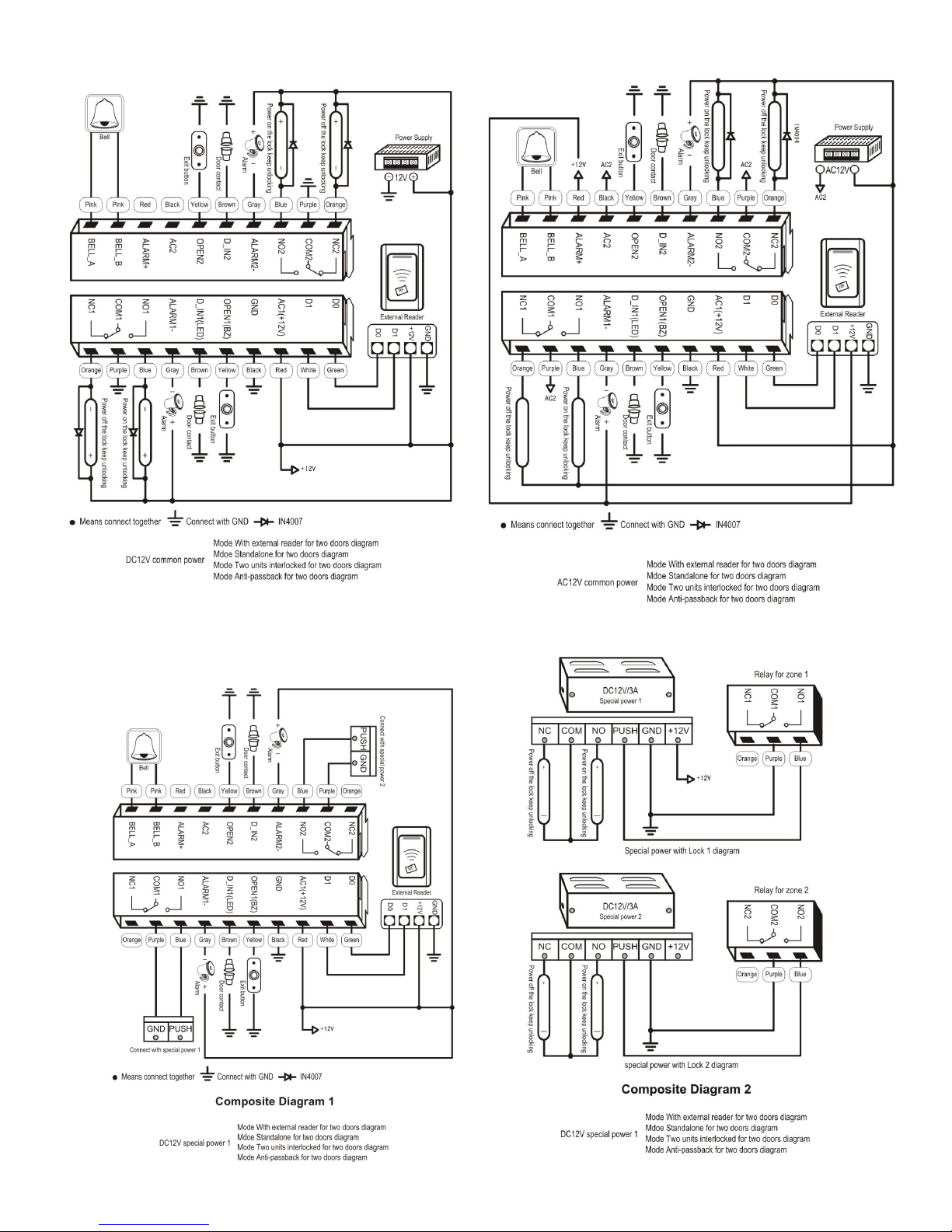
13. Wiring diagrams for all 7 working modes

13
14

15
14. Troubleshooting
Code Fault Fault cause Solutions
1 Close read range Quality of card Use original cards
2 Problem in PIN
setting
PIN is not standard First number of the PIN should be 1 or 2 to match with the
zone number. PIN shouldn’t be 1234. PIN is 4 to 6 digits.
3 PIN doesn’t open
the door
Using PIN 1234 1234 is the original PIN & can’t open the door. It should be
modified to another PIN. Set door opening mode to card or
PIN.
4 Alarms in normal
conditions
When installed, light leaks
under the bottom of the unit
Device should be installed flush to the wall.
5 No response after
card reading
Unit is not in ready (standby)
mode
Press * key, until the red LED starts flashing.
6 Keypad light is
not bright
Mode of keypad light setting is
wrong
Set keypad light as on or auto in user option settings.
7 Can’t enter
programming
mode
Forget the master code Reset to factory default, master code will be 999999. Only
installer data is restored, user data is unaffected.
15. Reset to factory default
Disconnect power from the unit.
Press and hold # key whilst powering the unit back up.
On hearing two ‘Di’ sounds, release the # key, system is now back to factory default
16. Issue record
Site:
Door 1 Location:
ID number User name PIN Card number Issue date
Please note it is always best to keep a digital copy of the issue record, especially on installations with over 10 users.
Site:
Door
2 Location:
ID number User name PIN Card number Issue date
 Loading...