

Page 1
www.InstroTek.com
CPN MC3 ELITE
™
Moisture/Density Gauge
OPERATING MANUAL
Page 2

‘This page may be removed from the
manual to prevent the unauthorized
access to the restricted menu functions of
the InstroTek/CPN MC-3 Elite.’
Restricted Menu Function
Access Code:
3548
Please note up to 2% of the mechanical components used in the gauge may
be recycled material.
Page 3

This page may be removed from the
manual to prevent the unauthorized
access to the restricted menu functions of
the InstroTek/CPN MC-3 Elite.
Page 4

© 2018 InstroTek, Inc.
MC-3 Elite Moisture/Density Nuclear Gauge
Operation Manual Version 4
Page 5

InstroTek
1
1. Table of Contents
****************************************
1. INTRODUCTION AND GAUGE COMPONENTS 2
2. GETTING STARTED 4
3. MENU FUNCTIONS 25
4. RADIATION THEORY 47
5. RADIATION SAFETY AND HEALTH PHYSICS 53
6. TRANSPORTATION 65
7. GAUGE THEORY 77
8. ROUTINE MAINTENANCE AND TROUBLESHOOTING 85
9. SPECIFICATIONS AND APPENDICES 92
10. INDEX 101
11. WARRANTY 110
Page 6

InstroTek
2
1. Introduction
Thank you for your purchase of the InstroTek/CPN Model MC-3
Elite. InstroTek/CPN has been a world leader in the
development and implementation of nuclear gauges for over
45 years. InstroTek/CPN design and manufacture gauges used
in variety of applications such as agriculture and irrigation
control, coal density and moisture determination, moisture in
pipe insulation and many more.
The Elite gauge was designed to meet the demands of the
construction market with reliability, accuracy and reduced
costs. It is designed to reduce the daily field effect of moisture
and dust, providing enhanced reliability and accuracy in all
rugged construction environments.
The software features are easy to follow. The four line display
provides large characters and intuitive instructions to help the
operators navigate through the different functions. The
diagnostics features allow the operators diagnose problems on
the field, increasing the gauge testing productivity.
Our technical staff includes some the most experienced
nuclear moisture/density gauge developers and engineers in
the world. We believe you will be impressed with the MC-3
Elite and its functionality.
We will provide you with a superior gauge, unmatched
expertise, and exceptional service.
Page 7

InstroTek
3
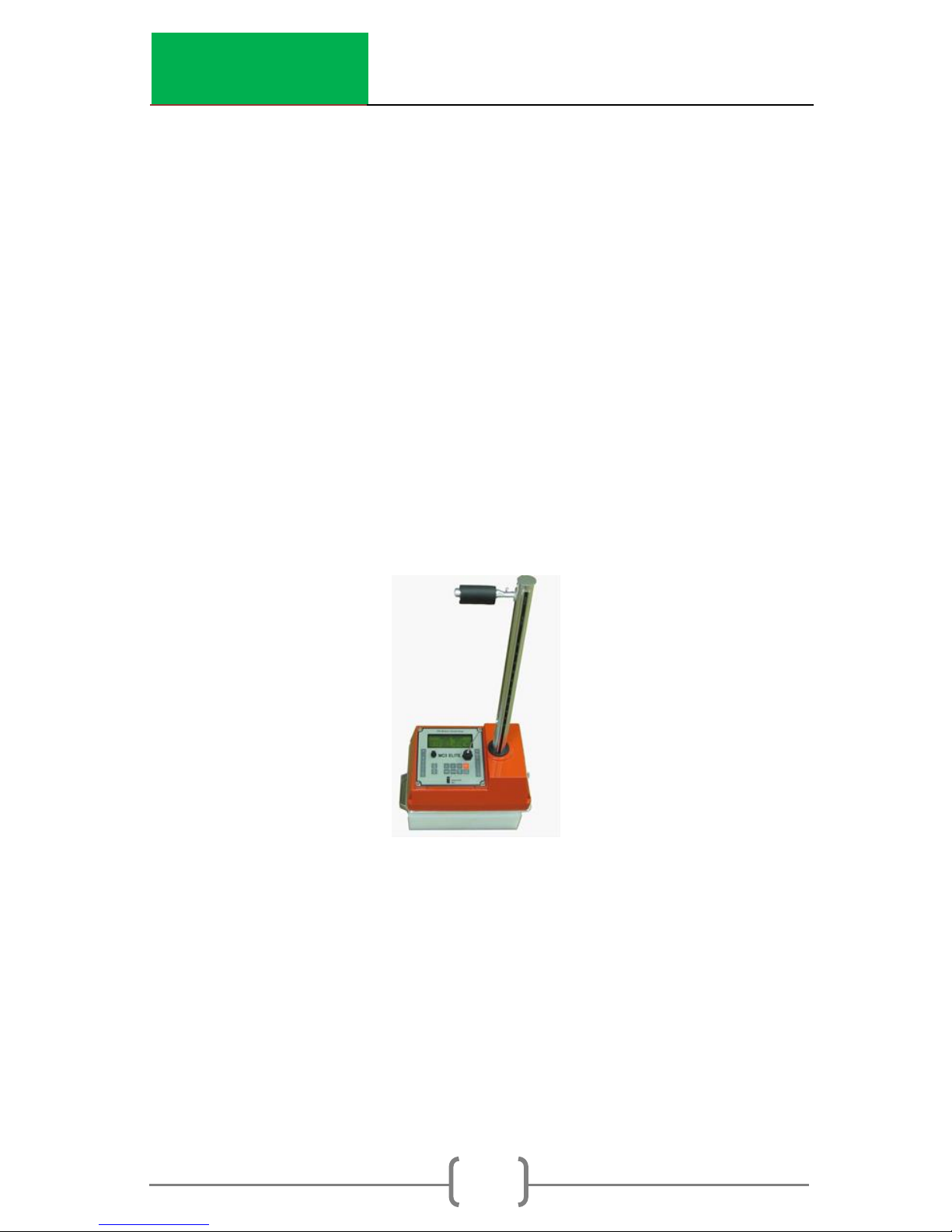
Model MC-3 Elite and Standard Accessories
Model MC-3 Elite
1. MC-3 Elite
2. Reference standard block
3. Scraper plate
4. Extraction tool
5. Drill rod
6. Type A shipping case
7. AC and DC charger, one each
8. Manual of operation and gauge paperwork
9. Gauge and Case Lock, one each
8
6
Fig 1.1 MC-3 Elite Nuclear Gauge & Accessories
1
2 3 4
5
7
9
9
1
Page 8

InstroTek
4
2. Getting Started
Before using this gauge, it is recommended that the user read
this manual and understand the operation of the gauge.
Operating your Model MC-3 Elite
This chapter covers the basic operation of your gauge from
powering on to taking a measurement. This manual should also
be used for Smart-MC electronic upgrade to older MC1 DRP
and MC3 gauges.
Important: In order to use this gauge, the operator is required to
meet and understand the provisions of the radioactive
materials license under which he/she is authorized to operate
this gauge.
Charging the Batteries
When the gauge is powered on, check for the low battery
warning (“N” or “NA” displayed). If the low battery warning
does not appear on the display, the gauge is ready for use and
does not require additional charge.
The MC-3 Elite contains 6 welded AA NiMH batteries. The
batteries are charged at the factory prior to calibration. Life of
rechargeable batteries depends on the number of
charge/discharge cycles. For best results, only charge your
batteries, when the battery low warning is displayed. The
gauge will display an “N” in the top right when the battery is
getting low. The gauge will display “NA” when the NiMH
batteries have been drained and the gauge has switched to
the alkaline backup.
The provided DC charger can be used for emergency charging
in the field. Plug this charger into your vehicle charger outlet
and charge the gauge for 30 minutes. This should provide
enough battery power to your gauge to complete your testing
Page 9

InstroTek
5
for the day. Charge the gauge overnight after the day of
operation.
During a charging session a “C” will appear in the upper right
hand corner of the display. The gauge is designed with a
SmartCharge chip that prevents the battery from over
charging.
The gauge cannot be turned off while the unit is being charged.
Page 10
InstroTek
6
Powering the Gauge On
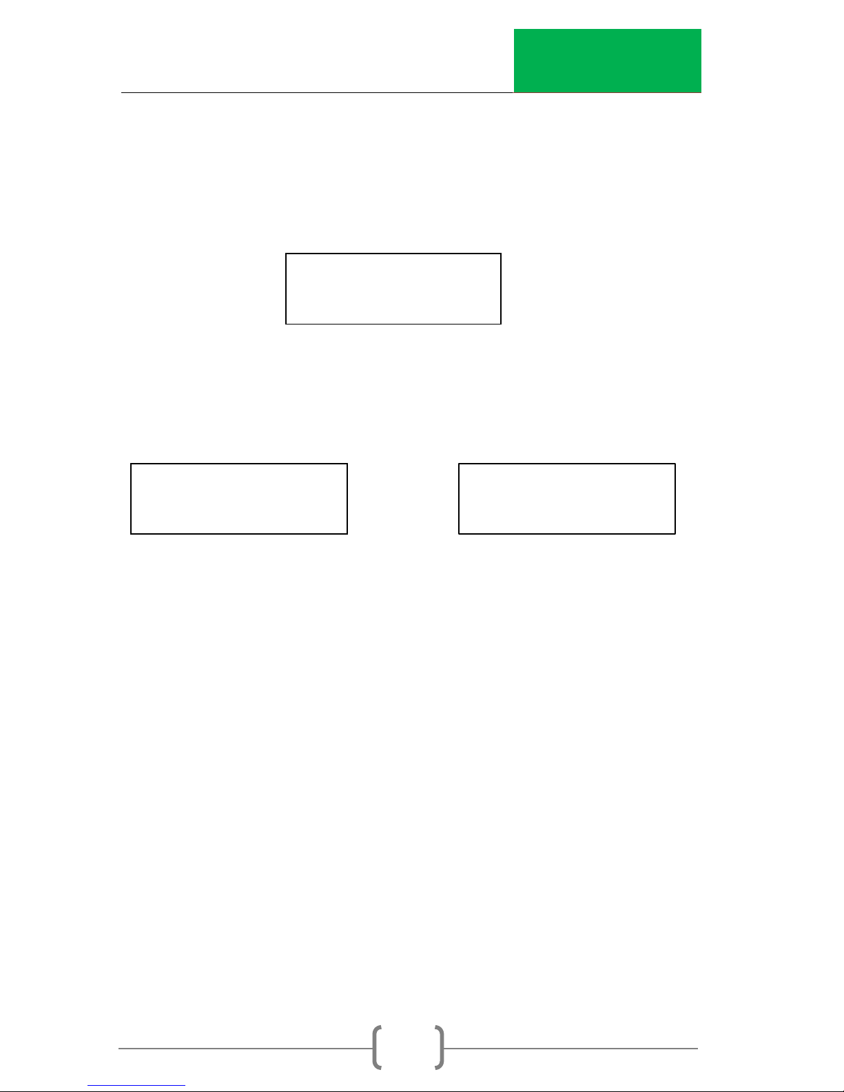
Use the ON/YES key to power the gauge on. When the gauge
is powered on the CPN Elite will go through the following SelfTest screens:
Self-Test will take approximately 15 seconds and checks for
proper operation of the keypad, density and moisture
detectors, and the High Voltage. Place the gauge on the
standard block during self-test.
The Gauge will go to the Ready display after a successful SelfTest. If a failure is detected during Self-Test, one or all of the
following messages will display on the screen.
1. Keypad Test Failed - This indicates a faulty keypad or a
stuck key. Pressing any key on the keypad during this test
will display this error. If a key is pressed by mistake during
this test, simply restart the gauge by powering off and then
on again. However, if the error is displayed again, contact
your InstroTek representative.
2. He-3 Tube Failure - If the gauge is on the reference
standard block during self-test, then there is a potential
problem with the electronics or the He-3 tube. If the gauge
is not on the reference standard block, place it on the
reference standard block and repeat this test. Contact
your InstroTek representative if this error is repeated;
3. GM tube failure - This indicates if one or both GM tubes are
not operational. Contact your InstroTek representative.
CPN Elite
Version: #. ##
High Voltage Test
Calibration
Reminder
Page 11

InstroTek
7
4. High Voltage Failure - This indicates the high voltage
module is not working properly.
Important: It is suggested to always power the gauge on and
allow the self-test to complete before leaving for a job site.
Place the gauge on the reference standard block and check
the results of the Self-Test and ensure there are no failures.
Charge the batteries if needed by the provided AC or DC
charger (Refer to the section on Charging Batteries).
Note: To preserve battery life for extended gauge operations,
the gauge will go into a shutdown mode if no key is pressed in
one hour. Simply press the ON key when you are ready to start
again. The gauge will not run the Self-Test if shut down was due
to an automatic one hour ‘inactive gauge shut down’ feature.
Page 12
InstroTek
8
Setting Units of Measurement
The default for the gauge is lb. /ft3 (PCF). You may change the
units to kg/m3 or g/cc by completing the following steps.
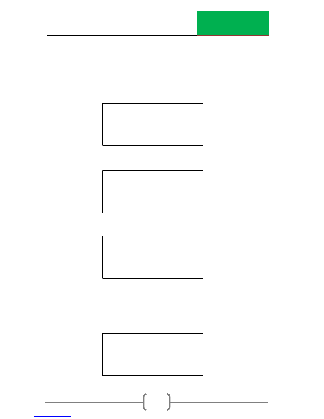
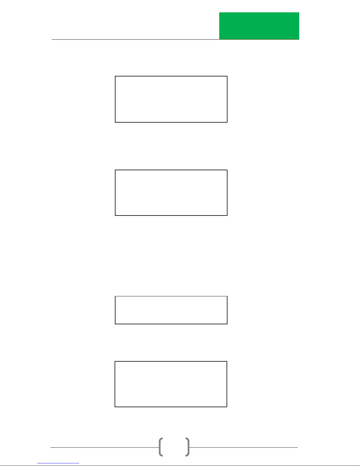
Press the MENU button, the first screen will be:
Scroll DOWN 5 screens
Press 12, (button 1, then 2)
Use the number buttons to select 1 for PCF (pounds per cubic
foot), 2 for kg/m3, or 3 for g/cc.
After selecting the Unit of Measurement, the Elite returns to the
menu screen.
11. Auto Scroll
12. Set Units
Up/DOWN FOR Next
Select3, ESC Exit
1. PCF
2. kg/m3
3. GCC
Select#, ESC Exit
11. Auto Scroll
12. Set Units
Up/DOWN FOR Next
Select#, ESC Exit
1. Recall
2. Set Depth
Up/DOWN FOR Next
Select#, ESC Exit
Page 13
InstroTek
9
Press ESC to return to the gauge ready screen
Setting Test Time
The gauge provides four different testing times: 15 seconds, 30
seconds, 1 minute, and 4 minutes. The gauge precision
improves with increased test time. In general, a one minute
count will result in a precision that is two times better than a 15
second count and a four minute count precision is twice as
good as a one minute count. Refer to your local specifications
for selection of an appropriate testing time.
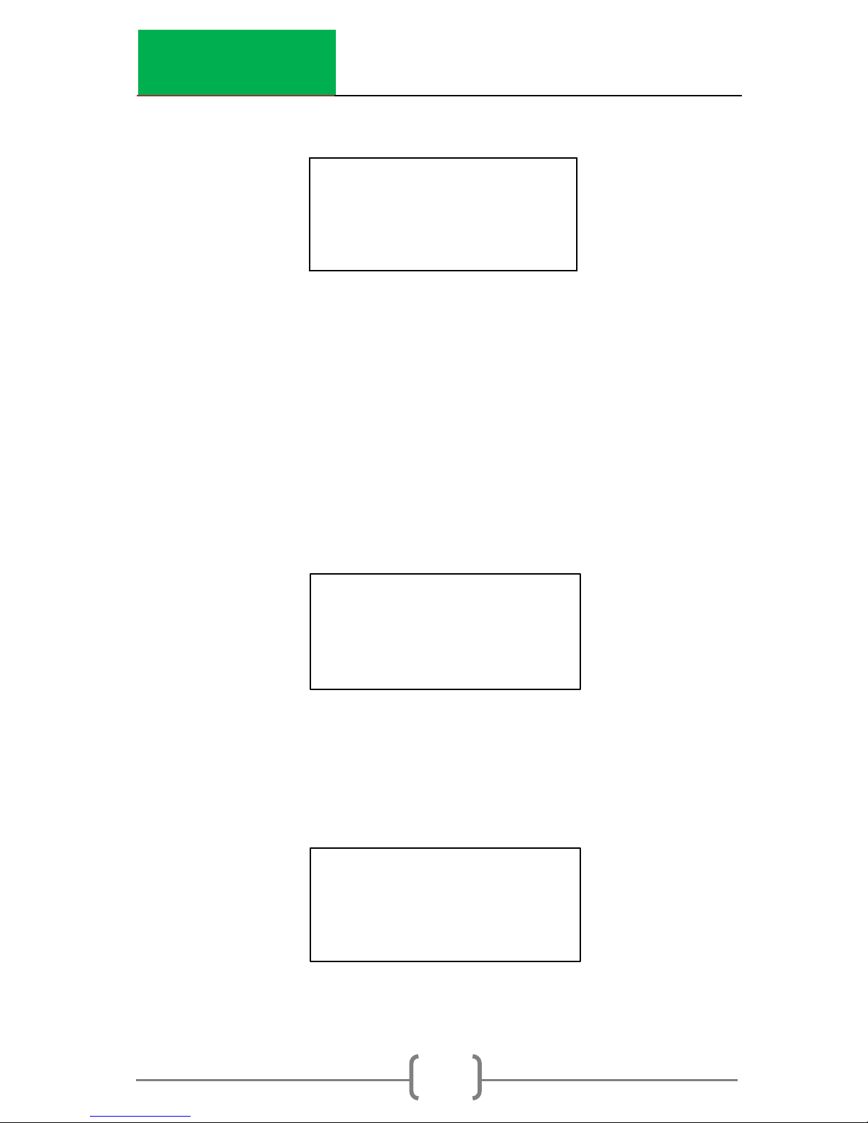
Press the TIME button on the front panel.
Scroll UP or DOWN to set a desired count time (15 seconds, 30
seconds, 1 minute, or 4 minute)
Press YES when you have chosen the time. You will be returned
to the gauge ready screen.
GAUGE READY
COUNT TIME: 1 min.
Depth: BS OFFSET: N
02/16/2013 12:07 PM
Cnt Time: 15 sec.
UP/DOWN TO CHANGE
YES TO ACCEPT
ESC to Exit
GAUGE READY
COUNT TIME: 1 min
Depth: BS OFFSET: N
02/16/2013 12:07 PM
Page 14

InstroTek
10
Measurement Depth
The Elite gauge is designed and is equipped with an automatic
non-contact magnetic depth indicator. The depth is
automatically read as you lower the source into measure
position and the appropriate constants are selected for
calculation of density.
The gauge can be placed into manual depth mode by
disabling the Automatic depth mode from the MENU functions
Taking a Daily Standard Count
It is important that a minimum of one daily standard count is
taken at each job site. The moisture standard count should be
within 2% and density standard count should be within 1% of the
average of the previous four standard counts. If the average of
the previous four standard counts is taken more than three
months from the current standard count, take four new
standard counts and generate a new average for comparison.
Check the density standard count and ensure it is within the
range of the expected standard count provided with the
calibration paperwork.
The standard count is used to correct for decay in the
radioactive source, especially for the Cs-137 density source.
Keeping a log of the daily standard counts is a good indicator
of gauge operation from day to day. Elite will store the last 30
standard counts in its memory. They can be recalled and
reviewed from the MENU functions. To obtain the most
representative standard count in the field, allow the gauge to
stabilize to the field environment for a minimum of 15 minutes.
Remember the following steps, when taking standard counts:
1. Find a level location close to the test site and
setup your polyethylene reference standard
block.
Page 15
InstroTek
11
2. Place the gauge on top of the standard block on
a level surface; the keypad end of the gauge
should be pushed against the metal butt plate.
See Fig 2.1.
3. Ensure the reference standard block is placed on
a dense material, such as soil, asphalt, or
concrete. Do not take standard counts on truck
tailgates, tables, or non-solid floors.
4. When you place the source rod in the “SAFE”
position notch, gently tap it down without pulling
the trigger to make sure the handle plunger is
properly seated inside the notch. Ensure the
handle is reasonably parallel with the gauge.
Fig 2.1 Reference Standard Count Position
Page 16
InstroTek
12
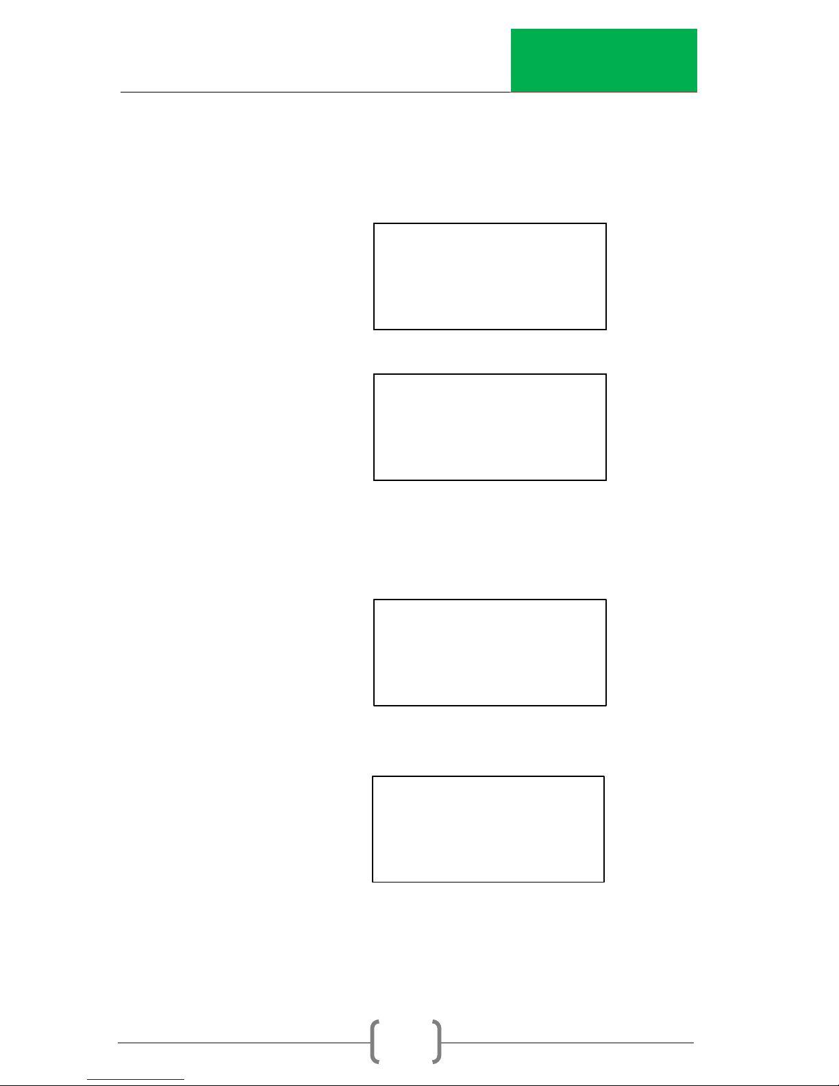
Press the STD button on the front panel. The Standard Count will
display with your previous standard count.
Press the ON/YES button to take a new count or press OFF/NO
to cancel and go to the gauge ready display.
Press the START/ENTER button. In Auto Depth mode, if the
source rod is not in the Safe position, the gauge will display a
message indicating “Depth not at Safe Position”
The time will begin to count down from 240 seconds (4 minutes).
After 240 seconds the results of your standard count will be
displayed
DS= ###
MS= ###
Take New Std Count?
Press YES or NO
Place Gauge on Poly
Std. Block in SAFE
Position
Press Start
Standard Count
Time: 240 sec.
DS= ###
MS=###
Use New STD CNT?
Press YES or NO
Page 17
InstroTek
13
DS is the density standard count and MS is the moisture
standard count. Log these numbers into your Daily Standard
Log Record (notebook), and then press the ON/YES button
The gauge ready screen will appear and you are now ready to
begin testing.
Note: If there are no standard counts in the gauge, a message
will display indicating “Invalid Std”. Take a new standard count
prior to testing.
Setting Target/Laboratory Density Values
The gauge is capable of calculating and displaying percent
compaction based on user defined laboratory values. Pressing
the MAX/PR button allows the laboratory value to be entered.
Select PR (Proctor) for soil/aggregate materials and Max. Dens.
(Marshall or laboratory max (rice) density) for percent
compaction on asphalt materials. Soil Specific Gravity (SG)
(which is used to calculate % Soil Air Voids) can also be
entered. %MAX, %PR, and %Soil AV will be calculated and
displayed automatically after each measurement.
Press the MAX/PR button.
1. Proctor
2. Max. Dens
3. Soil SG
Page 18
InstroTek
14
Press 1 for setting soil target value PR (Proctor), and
Press 2 for setting asphalt target value MAX (Max. Dens.).
Press 3 for setting soil specific gravity (SG).
Proctor
Press the ON/YES button
Once the PR value is entered, the gauge ready screen will
display.
Max Dens.
Press the ON/YES button
PR: #### PCF
Change value?
Press YES or NO
ESC to Exit
Enter Value For
Proctor: ### PCF
ENTER to Accept
ESC to Exit
MA: #### PCF
Change value?
Press YES or NO
ESC to Exit
Enter Value For
Max. Dens: ### PCF
ENTER to Accept
ESC to Exit
Page 19
InstroTek
15
Once the MA value is entered, the gauge ready screen will
display.
Soil SG
Press the ON/YES button
Once the SG value is entered, the gauge ready screen will
display.
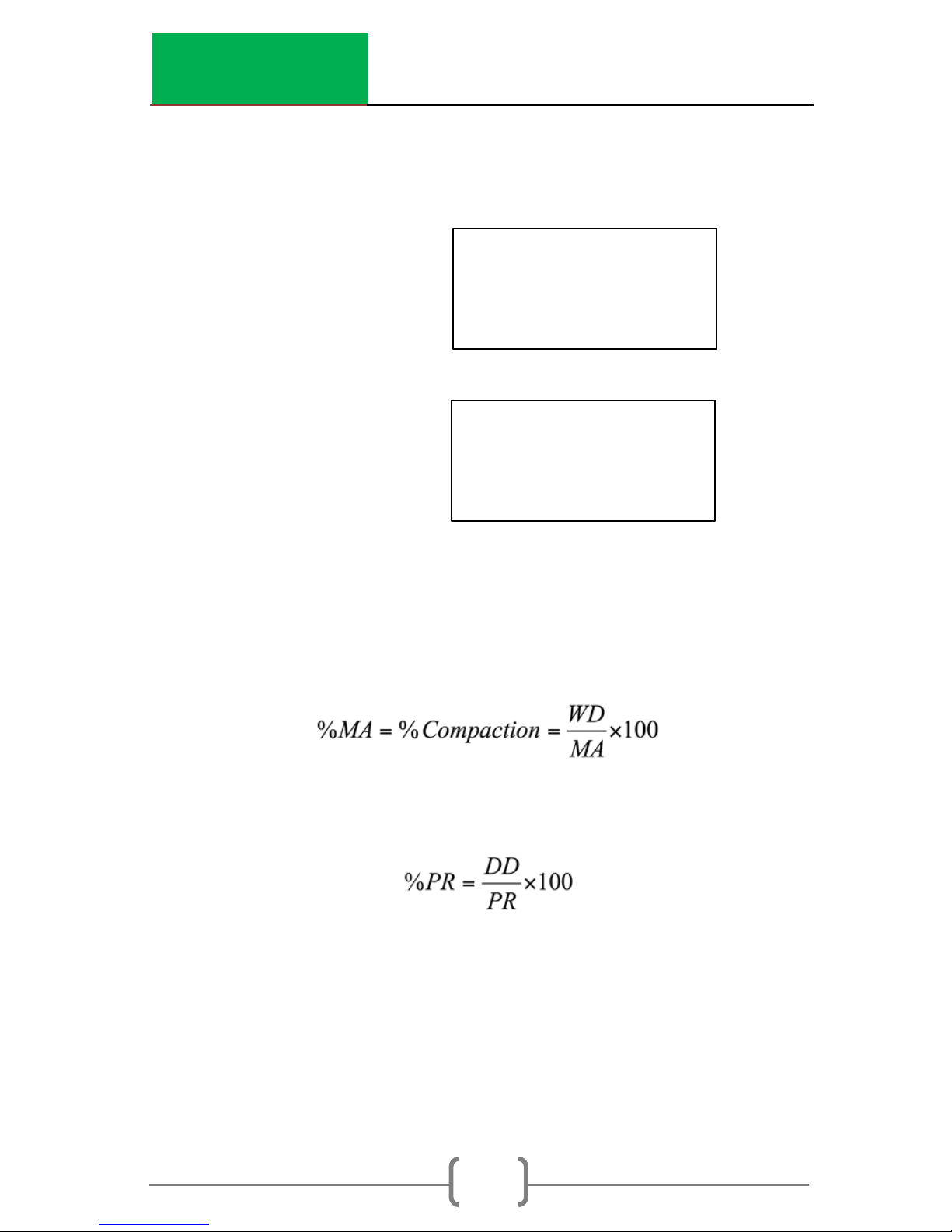
Equations used by the gauge
Where: WD (Wet Density) is measured by the gauge.
Where: DD (Dry Density) is calculated by the gauge. M
(Moisture) content is in PCF.
DD= WD - M
Soil SG: #### PCF
Change value?
Press YES or NO
ESC to Exit
Enter Value For
Soil SG: ### PCF
ENTER to Accept
ESC to Exit
Page 20

InstroTek
16
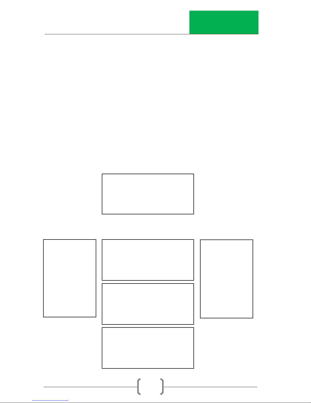
% PR can also be used to determine % Solids, if the “void-less
density” of the material can be determined.
Where: DD is the dry density in g/cm³, SG is the soil specific
gravity provided by the user, and M is the moisture content in
g/cm³.
Page 21

InstroTek
17
Site Preparation (soil, aggregates, and granular
materials)
1. Locate a test site away from other gauges and large
objects that could influence the gauge results. These
items include your truck, large concrete barriers or walls.
If the test site is required to be near or close to walls,
then refer to the special functions section, Offset and
Trench Correction.
2. Using the edge of the scraper plate provided, level the
test surface by removing raised areas and voids. If there
are any small voids that weren’t filled, use some
surrounding local soil or material to bring them up to
grade.
3. Place the extraction tool provided with the gauge over
one of the guides on the scraper plate.
4. Place the drill rod provided with the gauge into the
same guide as the extraction tool.
5. With a hammer of about 4-8 lbs., drive the drill rod into
the surface of the grade.
Caution: Eye, hand and shin protections must be worn
while forming a hole in the surface.
The drill rod has 6 notches spaced 2” apart, which are
numbered for the depth of the reading. These numbers
show the depth necessary to drive the rod for a
particular gauge depth reading. The rod depth
indicators automatically adds 2” extra depth to the
hole, which is necessary for accurate readings.
Page 22

InstroTek
18
6. Removal of the drill rod should be done in a manner
that will not damage the hole. Using a twisting motion,
pulling straight up on the drill rod might be the best way
to extract the rod from the material. Care must be
taken to preserve the integrity of the hole. Collapsed or
larger than required holes can negatively influence your
readings.
Page 23

InstroTek
19
Site Preparation (Asphalt)
1. Locate a test site away from other gauges and large
objects that could influence the gauge results. These
items would include work trucks, large concrete barriers
or walls.
2. For coarse, open graded mixtures, fine fill material, such
as Portland cement or fine sand, should be used to fill
the voids, but taking care not to completely cover the
surface of the asphalt. The gauge base should be
resting on the asphalt not the filler.
3. After the gauge has been placed on the test site, rock
the gauge back and forth by pressing on opposite
corners. Minimizing the amount of rock will ensure the
most accurate results achievable in the field.
Page 24
InstroTek
20
Taking Measurements
Lower the source rod to the desired depth by pulling the
handle trigger back and pushing down on the handle. In
positions of measurement, always ‘lock’ in to the position by
allowing the trigger to engage the notch and then gently
pushing the handle down to ‘seat’ on the notch.
Caution: Never drive the source rod into the soil by hammering
the gauge handle down.
To start measurement, press START/ENTER. The gauge will then
begin taking counts.
After the gauge has completed its count time, it will display:
Depth: BS
Time: 15 sec.
If you exit out
of the results
information,
you can use
the Recall
function
under menu
to retrieve
your results.
M Count: ##
D Count: ##
MCR: ### DCR: ###
Press UP/DOWN
WD: #. # PCF
%MA: #. #
%Voids: #. #
Press UP/DOWN
Moist: #. # PCF
# DD: #. # PCF
%Mois: #. #%PR: #. #
PRESS UP/DOWN
To make
recording
this
information
easier, you
can set up
the Auto
Scroll Feature
under Menu.
Page 25
InstroTek
21
Where:
M count = Moisture count
D Count = Density count
MCR = Moisture count ratio (M Count/MS)
DCR = Density count ratio (D Count/DS)
WD = Wet density
%MA = Percent Compaction ((WD/Max Dens.) X 100)
%Void = Percent air voids (100-%MA)
Moisture = Moisture density in PCF, Kg/m3 or gcc depending on
the unit selected
DD = Dry density (WD- Moisture)
% Mois. = Percent moisture ((Moisture/DD) X 100)
% PR = Percent Proctor ((DD/PR) X 100)
MM/DD/YYYY HH:MM AM
DEPTH: BS
Soil %AV: 10.0
PRESS UP/DOWN
Page 26
InstroTek
22
Project Storage and Printing
The Elite is equipped with data storage capability. Up to 10
Projects and 40 stations (readings) per project can be stored in
the Elite. The stored data can be printed or transferred into a
USB external drive located on the front panel.
To access this feature and start a new project press the Project
Print button:
Select 2 to start a new project. Press each alphanumeric key
repeatedly to select a desired letter. Advance to next letter by
pressing another alphanumeric key. Use the UP/DOWN button
to advance to the next position, if letter required is on the same
key as the one you have just selected. Press YES to accept
Choose 1 to auto store each station within the project. Press 2
to manually enter the station number.
1. Auto Store
2. Start New Project
UP/DOWN for Next
Select #, ESC Exit
Enter Project
Name:
YES to Accept
ESC to Exit
Starting Station
Number: ##
YES to Accept
ESC to Exit
Page 27
InstroTek
23
Choose the desired starting station number and press YES.
When Auto Store station is enabled, the station numbers will
increment up sequentially from the starting station number.
Choose YES to enable Auto Store to automatically store the
project after each reading. Otherwise, to store the data
manually, press the STORE key after each reading.
To use an existing Project or to print a Project, press the PROJECT
PRINT key on the front panel and select option 3.
Select Project from the list using the number choices.
To print, press the PROJECT PRINT key and select option 4.
Enable Auto Store?
Press YES or NO
3. Sel. Stored Proj.
4. Print Data
UP/DOWN for Next
Select #, ESC Exit
3. Sel. Stored Proj.
4. Print Data
UP/DOWN for Next
Select #, ESC Exit
Print Data
1. Print All Data
2. Print one Project
ESC to Exit
Page 28
InstroTek
24
Select which data you would like to print and press the
corresponding number button.
After you have selected the print option connect the printer to
the gauge and press ENTER.
To store to a USB device press, press the PROJECT PRINT Key and
scroll down to the third page, option 5
Select which data you would like to save and press the
corresponding number button.
Insert a USB drive and press ENTER.
To review or delete data for a particular project select the
PROJECT PRINT button and scroll down to option 6 or 7.
5. Send Data to USB
6. Review Data
UP/DOWN for Next
Select #, ESC Exit
Page 29

InstroTek
25
3. Menu Functions
This chapter contains functions that may not be used every
day. Features under Menu functions are important and will be
used periodically for testing under special circumstances and
special materials, performing diagnostics test and calibration
functions.
Pressing the MENU button on the front panel will access menu
functions. Some of the menu functions require an access code;
contact your RSO or your supervisor to obtain this code.
The following list of functions is available under MENU:
1. Recall – Recover/retrieve the most recent gauge test
results.
2. Offset – This mode provides three different offset
functions; Density, Moisture and Trench correction. Use
this function to offset factory calibration readings or
correct for influence of the trench wall in the field.
3. Auto Scroll – Helps users record data in the field. The test
screens automatically scroll every 5 seconds.
4. LCD Backlight – Enable/Disable the LCD backlight for
easy viewing of data and keypad during night work.
5. Diagnostic Test – Check the Battery Voltage, High
Voltage, Temperature, Memory Reset, Depth Sensor,
Key Pad Test, USB Store Test, Count Test, Shutdown Test,
Light Test and Extended Counts.
6. Drift Test – Test for electronic drift.
7. Stat Test – Test the electronic stability of the gauge.
8. Auto-Depth – Enable/Disable the calibration of the
Auto-Depth feature for calibration of the depth sensors.
9. Review STD Counts –View the last 30 Standard Counts
and the corresponding date for each standard count.
Page 30

InstroTek
26
10. Select Language – Select either English or Spanish for the
language.
11. Set Units – Change units between lb./ft3, kg/m3, and
g/cc.
12. Standard Mode – Enable/Disable Average Standard
Mode, Decay Mode and Chi2 Test Mode.
13. Serial Number – Enter the serial number of the gauge.
14. Date/Time – Set the current date and time.
15. Buzzer ON/OFF – Enable/Disable the buzzer/alarm
function of the Elite.
16. Special Calibration – Adjust calibration constants for
local and special materials.
17. Nomograph Mode – Enable/Disable mode so the gauge
can be used on thin layer asphalt overlays.
18. Calibration Constants – Enter and store calibration
constants used for determination of the material density
and moisture. This function is for authorized users only.
Description of each MENU function
1. Recall
This function allows you to retrieve and review the most recent
test data.
1. Press the MENU button.
2. Press the 1 button.
3. You can now scroll through the test information.
2. Offset
There are three offset options in the gauge: Density, Moisture,
and Trench.
Page 31

InstroTek
27
1. Density - allows the addition or subtraction of a given
quantity from the wet density (WD) readings measured
by the gauge. This function can be used for correction
of the gauge readings to other test methods, such as
asphalt cores tested by water displacement method.
2. Moisture - corrects the gauge moisture readings to oven
or speedy dry moisture.
3. Trench - corrects for the effect of trench walls to gauge
moisture readings.
To use the offset mode:
1. Press the MENU button.
2. Select the 2 button.
3. Scroll UP or DOWN to the offset you want to enable.
4. For entering a negative number use the DOWN button,
for a positive number use the UP button.
Density Offset - use this function to offset the density up or down
by a known quantity. For example, if the gauge’s wet density
(WD) is 142.0 PCF and the actual field density is 145.0 PCF, use a
density offset of 3.0 to correct the gauge readings. The offset
value can be positive or negative. The UP key is for the (+) sign
and the DOWN key is for the (-) sign. Follow gauge prompts to
enter this value.
Note: When density offset is enabled a Y on the gauge ready
screen will appear next to offset.
Moisture Offset - This function provides a means for correction of
gauge moisture results to results obtained by oven dry, speedy
Page 32
InstroTek
28
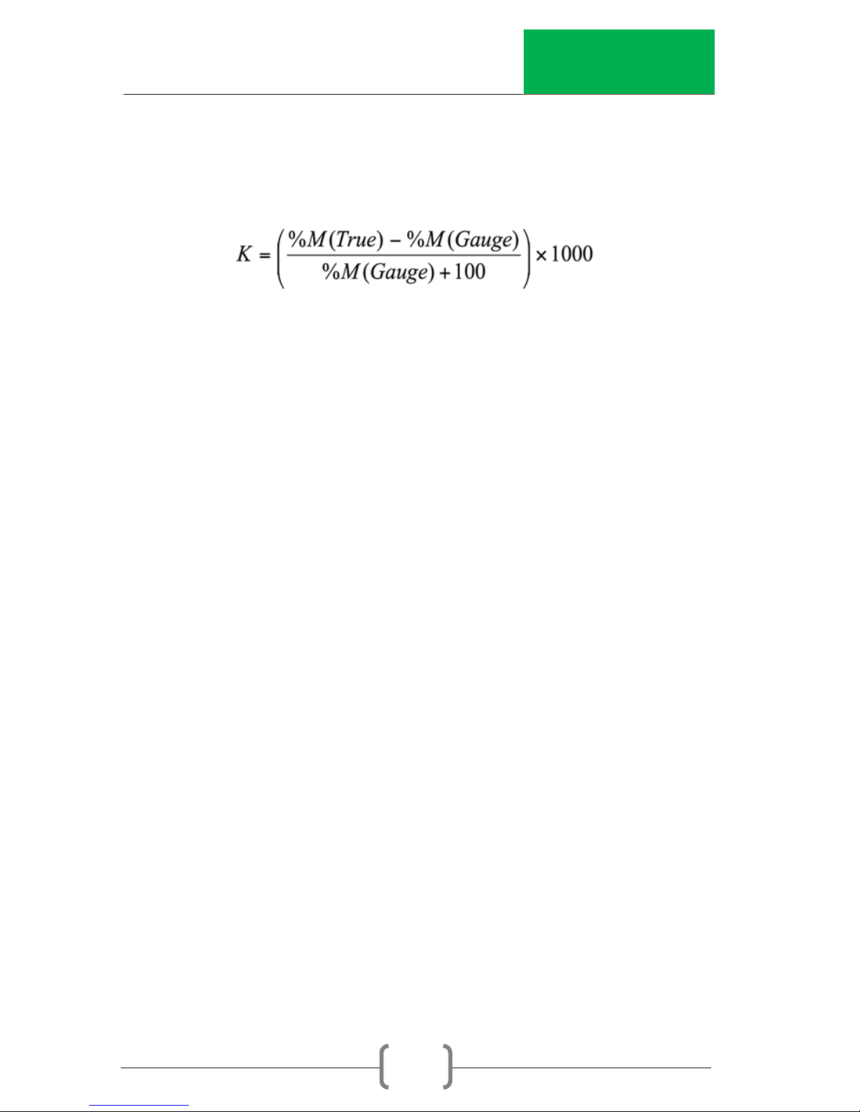
dry or other laboratory drying methods. Use the following
equation to calculate the correction and enter this value into
the gauge when prompted by the software.
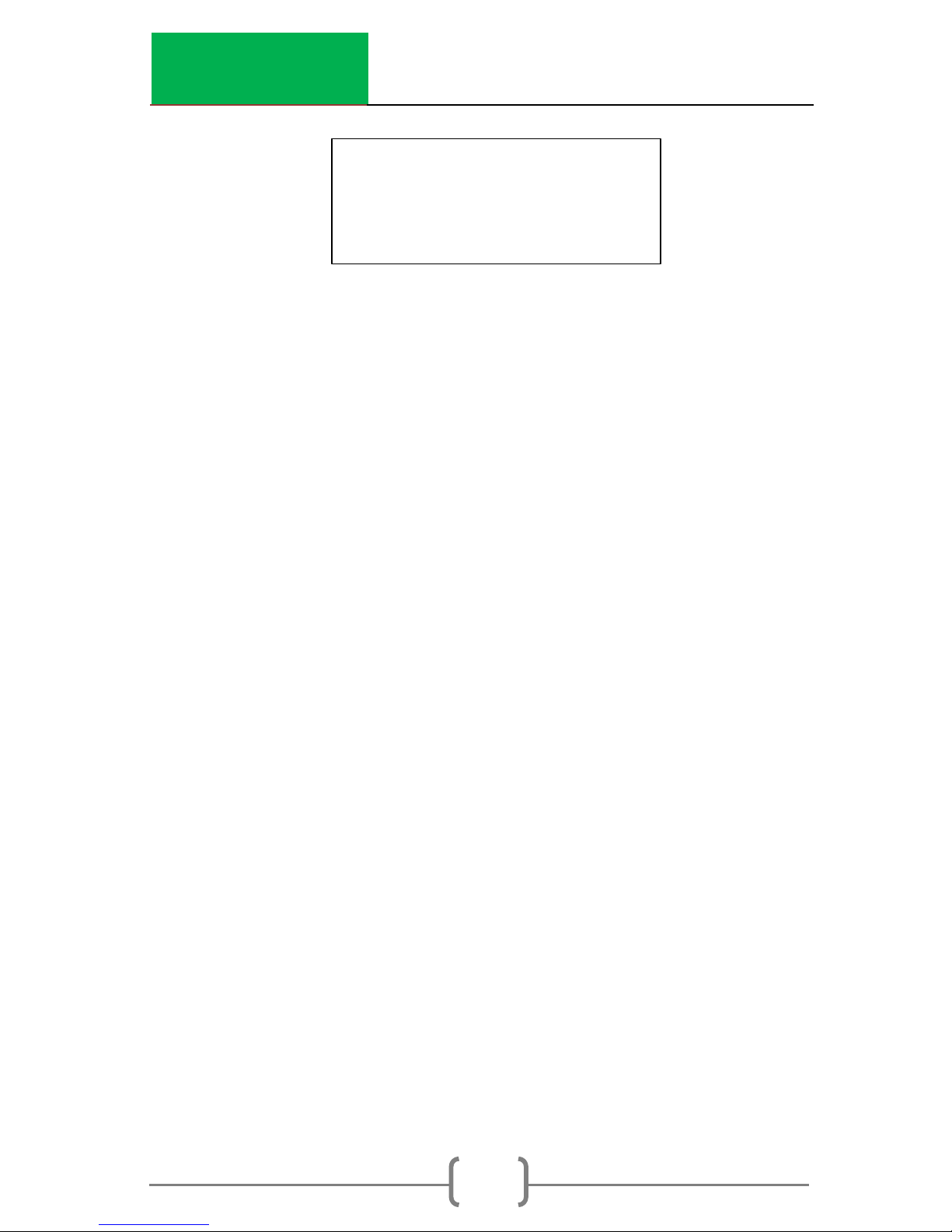
Where %M (Gauge) is the gauge derived % Moisture (%M)
value with K=0 (no moisture offset, factory calibration) and %M
(True) is % Moisture determined by oven dry, speedy dry or
other laboratory methods.
Once the K value is entered in the gauge, all subsequent test
results for moisture will be corrected by this offset. Use the UP
key for (+) sign and the DOWN key to enter (-) sign.
Note: When moisture offset is enabled a Y on the gauge ready
screen will appear next to offset.
Trench Offset - This function provides a means for correction of
wall influence on gauge moisture counts. Use this offset
function when taking measurements in a trench with walls 1
meter (3 ft.) or less from the gauge.
To use this function, take a standard count on the reference
standard block outside the trench and record the moisture
standard count, MS. Place the gauge on the standard block in
the center of the trench with the handle parallel to the wall in
SAFE position. Then press START. The gauge will automatically
calculate the Trench Offset by the equation
Trench Offset= MS – M Count
Page 33

InstroTek
29
The gauge is now in Trench Offset mode and ready to test.
Note: If M Count is lower than MS, then there is no influence
from the trench walls and trench offset is not necessary.
Note: When trench offset is enabled a Y on the gauge ready
screen will appear next to offset. Once a test begins, “T” will
appear on the screen, indicating Trench Offset mode.
3. Auto Scroll
The Auto Scroll feature allows for hands-free operation of the
gauge after a measurement has been obtained. When this
feature is enabled the test results will scroll from screen to
screen without the need to push the up or down buttons.
To enable this function:
1. Press MENU.
2. Press the 3 button for Auto Scroll.
3. Press YES to enable the feature.
After a measurement the screen will remind you that Auto Scroll
is enabled and after a few seconds the screen will change to
the results. Every 5 seconds the screen will display the next set of
results. Press the START/ENTER to begin a new measurement.
Note: Powering the gauge off will disable Auto Scroll
4. LCD Backlight
This feature allows for use of the gauge during night work. The
backlight will stay lit on the display and keypad for
approximately 20 seconds after a button is pressed.
To enable this feature:
1. Press MENU.
Page 34

InstroTek
30
2. Press the 4 button.
3. Press YES to enable.
4. To disable the feature repeat steps 1-4. The gauge will
prompt to disable the backlight if it is on, pressing YES
will disable the backlight.
Note: Powering the gauge off will disable the backlight feature.
Note: The backlight on the gauge causes a larger drain on the
batteries than under normal use. Only use backlight during
night work and when necessary.
5. Diagnostic Test
This function should be performed by a train technician and
under InstroTek’s instructions. In this mode the gauge can
check the following components and functions of the gauge:
Battery Voltage, High Voltage, Temperature, Reset Memory
and test the depth sensors.
Battery Voltage
This function measures and displays the total voltage on
the 6 AA NiMH batteries. The maximum measurable
voltage on the battery packs is approximately 9 volts.
The low voltage indicator comes on at 7.0 volts and the
gauge will shut off at 6.6 volts. Based on the condition of
the batteries and the usage, the gauge has a full day of
use from the time of low battery indication to shut off.
Use the car charger adaptor (DC charger) for charging
the batteries in the field.
Page 35

InstroTek
31
High Voltage
This function measures the high voltage on the board.
This information is very important for trouble shooting the
gauge and enables our technicians to provide
instructions on the status of the gauge. Please note, this
measurement will not be available on Smart-MC with
the old density and moisture modules.
Check Temperature
This function measures the temperature in the gauge
to determine if inconsistency in results is due to high
temperature. This information is very important for
trouble shooting the gauge and enables our
technicians to provide instructions on the status of the
gauge.
Memory Reset
Only a trained service technician should do this; it will render
the gauge nonoperational and may require the gauge to be
returned to InstroTek. This function is used in case the gauge
requires extensive work or repair. Memory clear erases all
stored information and in effect resets the gauge to precalibration factory defaults. The calibration constants will need
to be re-entered into the gauge.
Depth Sensor Test
This function measures the magnetic sensors at each depth to
ensure they are operational. This information is very important
for trouble shooting the gauge and enables our technicians to
provide instructions on the status of the gauge.
6. Drift Test
If there a consistent drift in the standard counts from count to
count or day to day, the electronics may have a drift problem.
This test monitors the long-term drift of the gauge. The drift test
Page 36

InstroTek
32
consists of performing five 240-second counts. To obtain a
meaningful drift result, first take a Stat Test (please refer to the
Stat Test) and wait 3-4 hours before starting a drift test. The
average of the five drift moisture and density counts is
compared against the average of the 20 one minute Stat test
averages. Passing limit on moisture is equal to 1.0% or less and
density is equal to 0.5% or less.
1. Perform a Stat Test on the gauge.
2. Wait 3-4 hours, and then begin the next steps. The
gauge may be used during this time, but if the gauge is
not functioning correctly, then it would be best not to
use it to obtain measurements.
3. After 3-4 hours, set the gauge back on the standard
block. Make sure the source handle is in the “SAFE”
position.
4. Press the MENU button. Press the 6 button.
5. Press START.
6. After 20 minutes, the results will be displayed.
7. If the gauge indicates a failing percentage, then
contact your InstroTek representative.
Note: Control the movement of other gauges during this test.
Always keep other gauges a minimum of 10 meter (30 feet)
away, while taking a Drift test.
Page 37

InstroTek
33
7. Stat Test
A Stat Test may be performed to validate the normal operation
of the gauge electronics. If two out of three stat tests fail the
limits set in the gauge, contact your InstroTek representative.
Passing limit on stat test results are R=0.25 to R=0.45.
To perform a Stat Test:
1. Press MENU.
2. Press the 7 button to do the Stat Test.
3. Place the gauge on a standard block on a level dense
surface, such as soil, asphalt or concrete. Make sure
you are 30 feet (10 meters) away from other gauges.
4. Place the source rod in the “SAFE” Position.
5. When the display reads Stat Test, press START.
6. After 20 minutes the display will show the results of the
test, you can scroll through to see each count.
7. If the test fails, repeat the test. If two out three tests fail,
contact your InstroTek representative.
Note: Control the movement of other gauges during this test.
Always keep other gauge a minimum of 10 meter (30 feet)
away, while taking a Stat test.
8. Auto Depth
The Elite gauge is equipped with an automatic non-contact
magnetic depth indicator. This function will disable the
automatic depth mode, if desired. If Auto depth is disabled,
Page 38

InstroTek
34
the gauge will prompt before every reading to manually enter
a depth.
Under this function, you can calibrate the depth sensors. In a
rare case, they may fall out of calibration.
Under Auto Depth function, select 1 to Enable/Disable the Auto
Depth, or 2 for Calibration and follow the screen prompts.
9. Review Standard (STD) Counts
The Elite gauge stores the last 30 standard counts and the date
of measurement. Use this function and the UP or DOWN key to
scroll through all the standard counts. A record of this data can
be downloaded by inserting a USB drive in the gauge and
pressing the STORE key. The standard counts will be stored in
the USB drive for future use.
10. Select Language
Elite is currently designed to work in two languages, English and
Spanish. (Press 1 then 0) Select 1 for English and 2 for Spanish.
11. Set Units
This menu function allows the gauge to set the default units to
pounds per cubic feet (PCF or lb./ft3), kilograms per cubic
meter (kg/m3), or grams per cubic centimeter (g/cc). The
MA/PR will need to be entered in the same units as the default
selection. Depth will be based on the units you select: either
inches for lb./ft3 or millimeters for kg/m3 or g/cc.
To set this option:
1. Press MENU.
2. Press the 11 button (1 then 1).
3. Select PCF, kg/m3, or g/cc with number keypad.
Page 39

InstroTek
35
12. Standard Mode
Two different Standard Count Modes can be selected and
used with the MC3 Elite, Average Mode and Decay Mode. The
gauge default is the Average Mode. In the Average Mode, the
percent change between the current standard count and the
average of the last four standard counts taken by the gauge is
displayed. The current standard count is used to calculate the
results of the Density and Moisture content.
The second mode is the Decay Mode. In this mode, the
elapsed time from the date of calibration is calculated and the
calibration density standard count is corrected for the Cs-137
decay. Cs-137 used in the gauge for density measurement
decays approximately 2.2% per year. The corrected calibration
standard count is compared to the daily standard count. The
Pass/Fail limit is set at ±1% of the decay corrected calibration
standard count. This calculation is done automatically by the
gauge and Pass/Fail limit is displayed. To ensure proper results in
this mode, the calibration date and calibration standard count
stored in the gauge has to be correct and current.
13. Serial Number
This function enters the serial number of the gauge to be
entered. This is set at the factory. Only authorized technicians
should use this function.
14. Date/Time
This function sets the date and time.
15. Buzzer/Alarm
This function enables or disables the Buzzer/Alarm. When this
function is enabled the gauge will beep when a key on the
keypad is pressed. Also, the gauge will sound an alarm after
completion of a test count.
Page 40

InstroTek
36
16. Special Calibration
Special calibration provides the functionality to adjust the
factory calibration in the field. Special calibration constant, B,
can be derived by the gauge, or may be entered by using the
equation given in this section for calculation of B.
The gauge is calibrated at the factory to “average soil”, which
is defined as material that is half way between pure granite
and pure limestone. For most soil and aggregate materials,
average soil approach results in accurate density
measurements. However, there are cases when the material
composition being tested is much different than the range of
materials covered by the factory calibration. Special
calibration provides the user the opportunity to calibrate the
gauge to local materials and materials not covered by the
factory calibration.
In the special calibration mode, a new B constant is calculated
by using an actual field sample and obtaining the “true
density” of the sample. The B value is the only constant in the
gauge that is influenced by the material composition. So
changing this constant is the most effective way to account for
material composition changes in the field.
To perform a special calibration for a local material that may
not be covered by the factory calibration, take a minimum of
four and a maximum of 10 density counts in the field on the
material the gauge is to be used on. For granular materials, use
direct transmission readings and for asphalt, use BS readings.
Average the counts. Obtain samples from the locations where
gauge reading are taken. Analyze the samples in the lab and
determine the density of the material (“True Density”) in kg/m3.
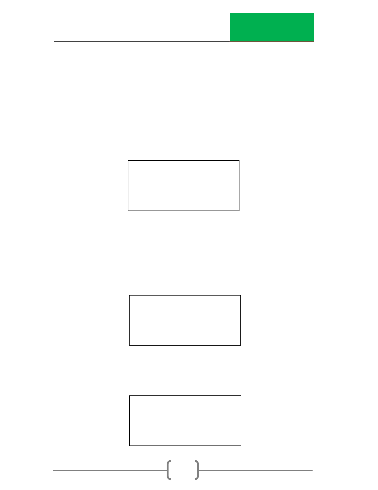
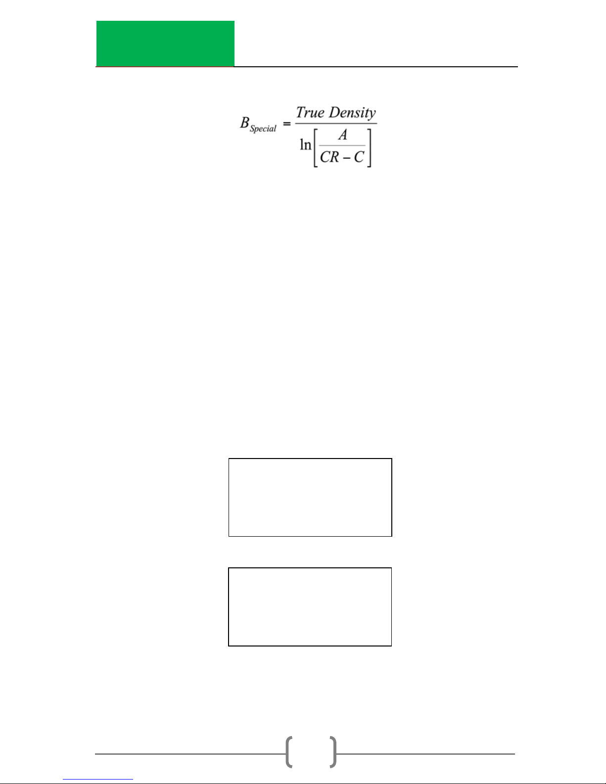
Use the following equation to recalculate the B value that will
be entered in the gauge.
Page 41
InstroTek
37
Where CR is count ratio (Average count/std. count)
determined by the gauge in the field, A and C are calibration
constants for the depth of measurement used in the field and
True density is density determined by a conventional method in
the lab.
Note: The gauge can perform the calculations if counts and
true density values are determined and input in the gauge
software. Furthermore, the gauge software is written so that the
entire special calibration function process, including collection
and storage of counts, is performed by the software. Follow
gauge instructions to perform Special Calibration.
To use the Special Calibration Function:
Press MENU:
Press 1 THEN 6
15. Buzzer Alarm
16. Special Cal.
UP/DOWN for Next
Select #, ESC Exit
Enable Special
Calibration?
Press YES or NO
ESC to Exit
Page 42
InstroTek
38
Press YES to Enable Special Calibration and NO to go back to
the gauge ready screen.
Note: If special calibration has been used previously, the gauge
will ask if the same calibration or previously stored data should
be activated. At this point, the previously used special
calibration may be activated or select to start a brand new
special calibration.
At this point, the gauge provides the option to derive the Spec
Cal constant B or entering the constant previously derived.
When ‘Yes’ is selected, the gauge will prompt to select the
number of counts required to take on the material. It is
recommended that a minimum of four and maximum of ten
readings are selected for this test.
(Select 1 to 10 readings)
Use Gauge to Derive
B Value?
Press YES or NO
ESC to Exit
Enter Number
of Counts: ##
ENTER to Accept
ESC to Exit
Depth: BS
UP/DOWN TO CHANGE
YES to Accept
ESC to Exit
Page 43
InstroTek
39
Select the number of counts and desired depth.
Place the gauge on the material at a desired location and
press start to accumulate the first count. The gauge will prompt
you to take counts until the selected number of counts has
been completed. Record each individual count taken. Even
though these counts are not needed for gauge derived
calculations, it will provide you with a record of this data. It is
recommended that the gauge be moved to a new test
location for each one of the counts. Follow the screen prompts
to complete the counts.
After all counts are accumulated, the gauge will average all
counts and will ask you for the “True” material density. “True”
density is achieved by collecting a representative material
sample from the field and analyzing this material in the
laboratory by using a conventional density test. You may also
consider using other test methods such as sand cone and
balloon methods in the field for determination of “True” density,
if specified by local agencies or specifications.
If you have the “True” material density, you may enter it at this
time. Otherwise, you may enter this value at a later time. The
gauge will save the counts for use at a later time. If you select
‘Yes’, the gauge will prompt you for density input.
Enter Value For
Density Now?
Press YES or NO
ESC to Exit
Enter Value for
Density= ## PCF
ENTER to ACCEPT
ESC to Exit
Page 44

InstroTek
40
Once the density is entered, the gauge will calculate a B value
and go into the Special Calibration mode. Record the B value.
During measurements Special Calibrations will appear on the
screen to indicate that the gauge is in special calibration
mode. If the operator turns off the gauge, Special Calibration is
automatically disabled and factory “normal” calibration is
activated. The gauge will maintain the previous B value until it
is over written by a new special calibration test.
Note: If operating in g/cc mode, the gauge will prompt to enter
the density in kg/m3 (g/cc x 1000).
Important: Record and save the B value for future use. Having
the B value eliminates the necessity of going through the
gauge derived process.
It may be more practical to enter the density at a later date. If
a density value is not entered after taking counts on the
material, on the next Special Calibration, the gauge will prompt
to use the stored data. This data contains the counts taken on
the most recent use of Special Calibration function.
Page 45
InstroTek
41
Value B may be entered directly into the gauge special
calibration function if available from previous calculations.
To enter the B value, press YES to activate the special
calibration.
17. Nomograph
The Nomograph function allows for measurements of thin
overlay density on asphalt or concrete. Do not use this mode
for asphalt on asphalt or asphalt on concrete surfaces. The use
of regular BS mode will produce more repeatable results on
asphalt and asphalt on concrete projects. Since the density
variation between the top and bottom material for asphalt on
asphalt and asphalt on concrete pavements are minimal, use
of the Nomograph mode does not guarantee more accurate
results. The influence from the bottom material is masked by the
top material density and the results of the Nomograph mode
and BS mode will not be different. Only use the Nomograph
mode for parking lots or projects with asphalt on top and soil or
aggregate sub base on the bottom. Under these conditions,
Nomograph mode results will be more accurate than the BS
mode of the gauge.
B=######
Activate Special
Calibration?
Press YES or NO
Page 46
InstroTek
42
To use the Nomograph mode, place the source in the BS
position. Obtain the top material thickness and the density of
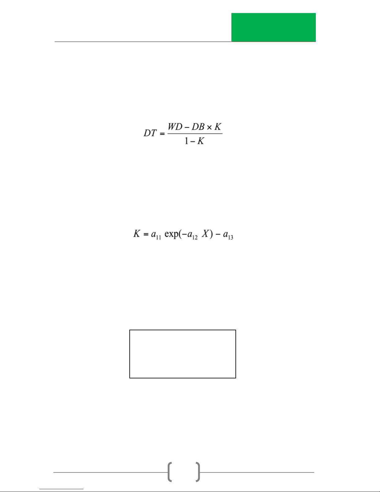
the material immediately under the thin overlay. The equation
used for calculation of the overlay density is:
Where DT is the overlay density, WD is the wet density measured
by the gauge and K is the effect of the top layer on the density
measurement. K is dependent on top layer material thickness
and is defined by:
X is the top material thickness and , , are constants
derived at the factory.
The gauge software automatically performs Nomograph
calculations. To use this function, select the menu item and
press the 17 button.
Select YES to enable the Nomograph function. Follow the
screen prompts to enable the Nomograph mode.
Enable Nomograph
Mode?
Press YES or NO
ESC to Exit
Page 47
InstroTek
43
Enter Nomograph material thickness in inches or mm,
depending on the unit already selected in the gauge. The
range of thicknesses that can be used with this function is 1 to
3.5 inches (25 to 90 mm). Do not use this function for thickness
outside this range, as the results will not be accurate.
Enter the density of the material immediately under the top
material. To obtain this density, use the gauge to measure the
material density prior to construction of the overlay.
Once bottom material density is entered, the Nomograph
mode can be activated. During measurements, “Nomograph”
is displayed to indicate Nomograph is active. If the gauge is
turned off, the Nomograph mode is disabled. Enable this
function again through the menu by following gauge prompts
and activating the most recent saved data.
The most recent Nomograph function inputs will remain in the
gauge until a new set of thickness and bottom density data is
entered for a new job.
Enter Material
Thickness: ## in
ENTER to Accept
ESC to Exit
Enter Bottom
Density: ## PCF
Enter to Accept
ESC to Exit
Page 48

InstroTek
44
18. Calibration Constants
This function will require an access code. Contact your RSO or
InstroTek to obtain an access code.
Note: Only someone familiar with nuclear gauge setup and
calibrations should perform these steps. Changing this
information will result in erroneous readings.
To enter calibration constants:
1. Press MENU.
2. Press the 18 button (1 then 8)
3. Press ENTER.
4. Enter access code using the number keypad.
5. Press the 0 button to change the Moisture constants (E
and F) for entering a negative number use the DOWN
button, for a positive number use the UP button.
6. The depths will be displayed. Scroll to the desired depth
and press the corresponding number for desired depth.
A, B, and C constants can be set for each depth. Use
the DOWN key to enter (-) sign. After all depths have
been entered and you are back at the select the depth
screen, you can press the ON/YES button to take you
back to the gauge ready screen.
7. If the gauge units are in PCF, the calibration constants
are displayed and entered in PCF. If the gauge units are
in kg/m3 or GCC, the calibration constants are
displayed and entered in GCC. There may be rounding
errors when switching between units.
Page 49

InstroTek
45
Other Features of the Model MC-3 Elite
Note: Only trained technicians should perform these functions.
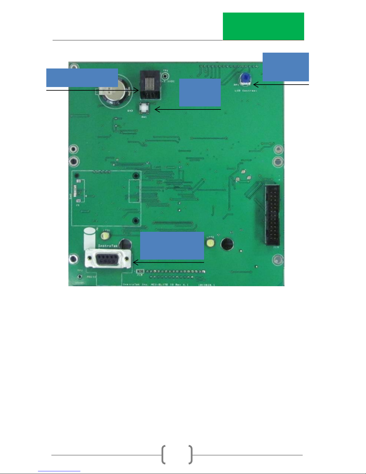
The Reset Button - This button will reset the operating program. If
the program freezes or stops responding, then pressing this
once will reboot the system. The gauge will not lose calibration
constants, standard counts, or last measurement. However, the
LCD back light and Auto Scroll set will need to be re-enabled.
The scaler will need to be removed from the gauge to use the
reset button. Simply unscrew the four screws on the front of the
panel, lift out of the housing, and turn over the scaler. The reset
button is on the top of the scaler circuit board. See Fig 3.1
RS-232 - This connection will download the constants into the
gauge with the aid of the computer software. Please contact
InstroTek, for more information.
J-45 - This connection is only used at the factory to program the
system software used on the Model MC-3 Elite. Do not plug any
wires to this connection, as it could damage the scalar and will
void any warranty in effect on the gauge.
Display Contrast - This dial sets the contrast of the LCD; this can
be changed to the liking of the user. Using a small screwdriver,
adjust the contrast level.
Page 50
InstroTek
46
Fig 3.1 Backside of the Front Panel circuit board
J45 Connector
RS232
Connector
Reset
Button
Display
Contrast
Page 51
InstroTek
47
4. Radiation Theory
This chapter covers information on basic atomic physics. It is
important that the users have an understanding of this section
in order to have a handle on applications and safety related
issues.
Elements/Atoms
Elements are combinations of the three sub-atomic particles:
Protons, Electrons and Neutrons. Each element has unique
chemical properties. Typical elements are Silicon, Oxygen,
Gold, Copper, and Iron. Currently 118 primary elements have
been identified, 90 natural, the rest man made. A few of the
elements have been created only in the laboratory, but they
decay very quickly.
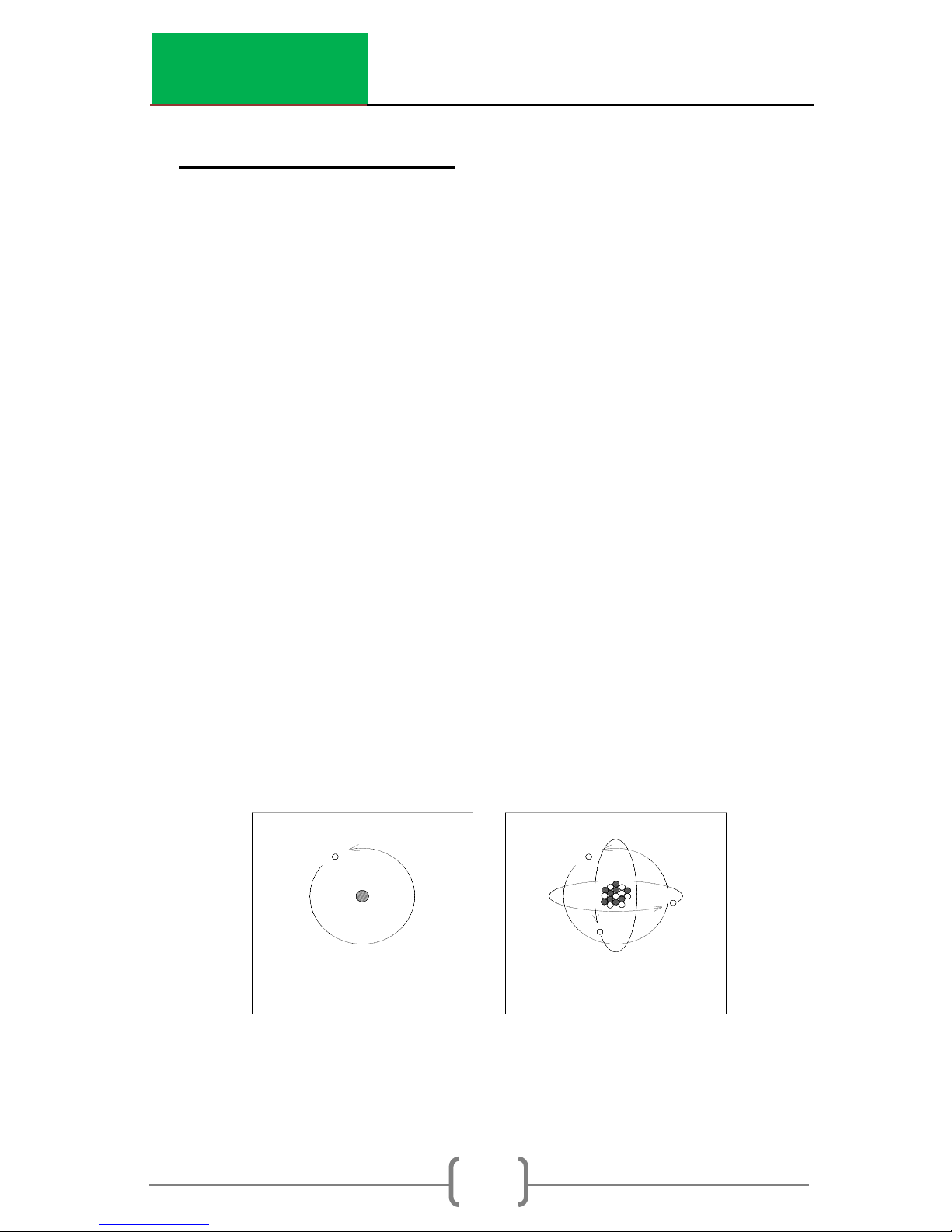
Atom is a Greek word for indivisible. The simplest element/atom
is hydrogen. It has one proton, no neutrons, and one electron.
A more complex element is oxygen that has 8 protons and 8
neutrons in the nucleus, and 8 electrons in orbit.
ELECTRON -1
NUCLEUS +1
1
HYDROGEN H
1
16
OXYGEN O
8
NUCLEUS +8
ELECTRONS -8
Fig 4.1 Examples of Atoms
Page 52

InstroTek
48
The atom is not solid, it is mostly space. If the nucleus of
hydrogen was the size of a marble and placed on the 50 yard
line of a football stadium the electron would be the size a
pinhead in the stands.
Each element/atom has been assigned a one or two letter
symbol that is an abbreviation of its name (generally Latin).
Symbol Latin English
Au Aurum Gold
Cu Cuprum Copper
Fe Ferrum Iron
The atomic number (Z) is the number of protons in the nucleus
The mass number (A) is the sum of the protons and the neutrons
in the nucleus.
Isotopes
Elements that have the same number of protons (same atomic
Number), but different numbers of neutrons (different atomic
mass numbers) are called Isotopes. Hydrogen has three
isotopes. The most abundant hydrogen isotope has one proton
and no neutrons. The isotope of hydrogen with two neutrons is
called Tritium and is unstable. Tritium is produced in the
atmosphere by neutron bombardment of nitrogen.
Page 53
InstroTek
49
Earth’s Crust
Our task is to measure the density of soils. The elements in the
periodic table we are concerned with are those in the earth’s
crust.
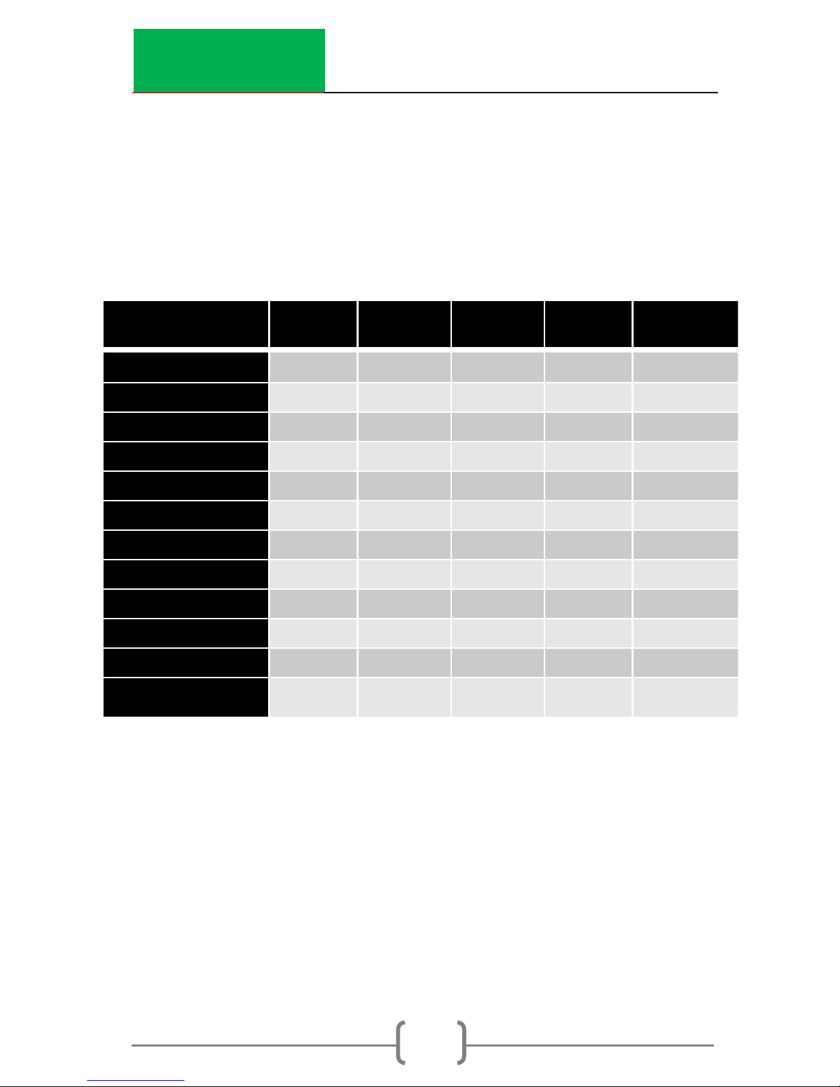
The density of a material is dependent upon its atomic mass
(A). But the count rate in the nuclear density gauge is
dependent on the number of electrons (atomic number (Z)).
For the most materials in the earth’s crust this presents no
problem since the ratio of the atomic number to the atomic
mass (Z/A) is approximately 0.5.
ELEMENT
SYMBOL
No.
(Z)
MASS
(A)
Z/A
% EARTH’S
CRUST
Oxygen
O
8
16.00
0.5000
49.9%
Silicon
Si
14
28.09
0.4984
26.0%
Aluminum
Al
13
26.98
0.4818
7.3%
Iron
Fe
26
55.85
0.4655
4.1%
Calcium
Ca
gamm 20
40.08
0.4990
3.2%
Sodium
Na
11
22.99
0.4785
2.3%
Potassium
K
19
39.10
0.4895
2.3%
Magnesium
Mg
12
24.31
0.4936
2.1%
Other
2.8%
Hydrogen
H
1
1.008
0.9921
Water
H2O
10
18.016
0.5551
Page 54

InstroTek
50
Radioactivity
Not all Isotopes are stable. Isotopes with atomic numbers
greater than 92 are unstable. Americium used for moisture
measurement in the nuclear gauge has an atomic number of
95. It is a by-product from neutron bombardment of Plutonium
to produce weapons materials. All 13 isotopes of Americium
that have been identified are radioactive.
Some isotopes of lower atomic number are also unstable;
Cesium-137 used in the nuclear gauge for density
measurement has an atomic number of 55. Of 22 isotopes
identified, Cesium-133 found in nature is stable, while Cesium137, a by-product of making atomic weapons materials, is not.
By nuclear reactions, man has produced a large number of
unstable isotopes not found in nature.
Any unstable isotope that gives off energy—while decaying to
a stable isotope—is defined radioactive. Like other forms of
energy, radiation can be useful or harmful depending upon its
use.
Alpha, Beta, Neutron, and Gamma Radiation
Sources used in the nuclear gauge are composed of four types
of radiation: Alpha particle, Beta particle, Photons (gamma
rays), and Neutrons.
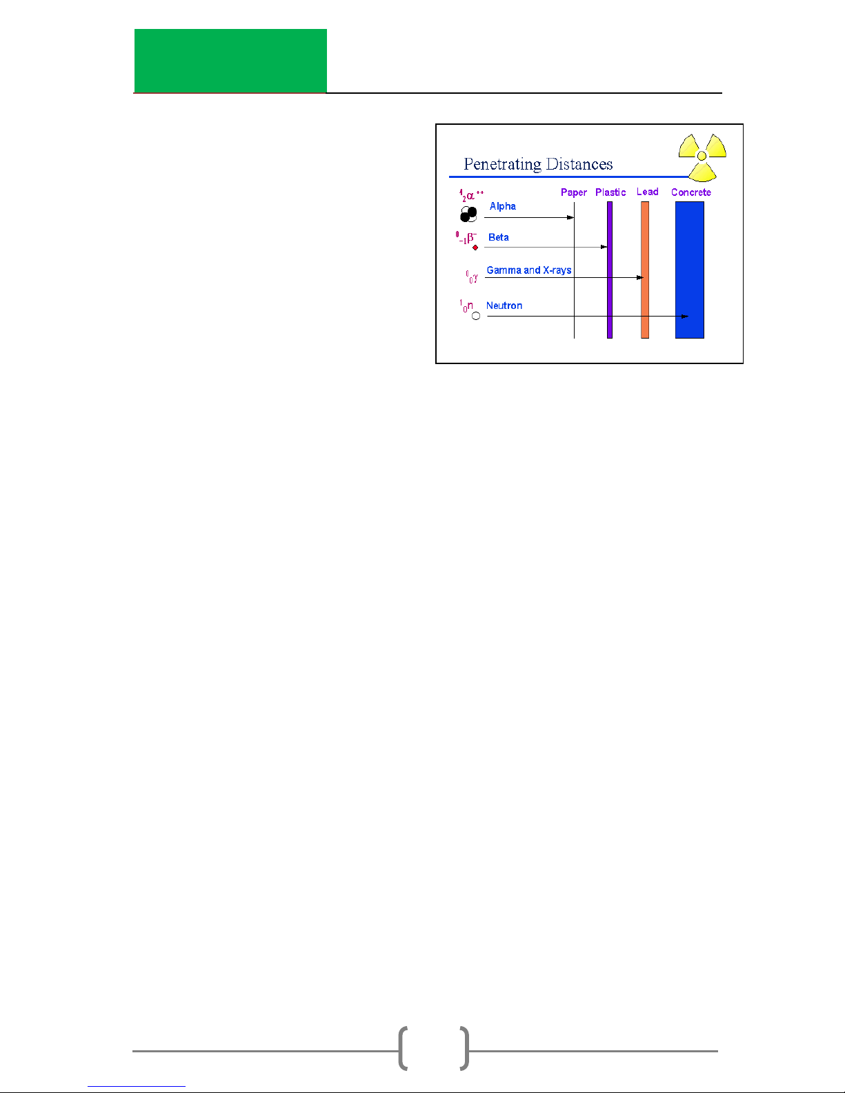
Alpha Particles travel only about an inch in air and are stopped
by a sheet of paper or the skin tissue. In the nuclear gauge,
alpha particles are used to produce neutrons.
Page 55
InstroTek
51
Fig 4.2 Penetrating Distances
Beta particles travel a few
feet in air and are stopped by
an inch of wood or a thin
sheet of aluminum or plastic.
In the nuclear gauge beta
particles are stopped by the
source containment.
Gamma rays travel hundreds
of feet in air and can be
shielded by thick lead or
concrete.
Neutron particles travel hundreds of feet in air and can be
shielded by water, plastic, or special concrete.
Cesium-137 and Americium-241/Be are used in the Elite
portable moisture/density gauge and they produce all four
types of ionizing radiation. The alpha and beta radiation will
be stopped by the stainless steel source containment. Only
neutron and gamma radiation contribute to occupational
radiation exposure.
Neutron radiation
Neutron radiation in the Elite gauge is produced by alpha
particles from the Americium 241 bombarding the Beryllium.
Neutron radiation has no charge and is very penetrating. To
shield against neutron, the first step is to slow down the neutron,
which is called thermalization. Thermalization is achieved by
interaction of neutron with particles of same mass as neutron,
like hydrogen in water or polyethylene. As neutrons collide with
these particles, neutron energy is reduced allowing for effective
absorption by the shielding material.
Page 56

InstroTek
52
Gamma radiation
Gamma radiation is electromagnetic radiation that is released
from nuclear reactions. X-rays, radio waves and light are some
other examples of electromagnetic radiation. Gamma rays and
visible light have no electrical charge or mass and travel at
speed of light. Unlike visible light, gamma rays are very
energetic and can penetrate several inches of solid material.
The gamma source in the Elite gauge in the process of
decaying to Ba-137 releases beta particles which will be
stopped by the capsule wall. The Cs-137 releases gamma ray
energy of 0.662 Mev. This gamma energy is used to determine
the density of the material.
Half-Life
An important characteristic of radioactive material is that its
activity decays with time. The half-life (T1/2) of a radioactive
material is the time it takes for half the atoms in any given mass
of the material to decay. Half-lives vary from fractions of a
second to millions of years. After ten half-lives only 1/1,000th of
the radioactivity remains.
The two sources in the MC-3 Elite model are Cesium-137 for
density measurements and Americium-241/Be for moisture
measurements. Cs-137 has a half-life of 30 years, while Am-241
has a half-life of 432.2 years.
To correct for decay, a standard count is taken each day of
use and the ratio of the measured count on a material to the
standard count, defined as Count Ratio, is obtained. The count
ratio automatically corrects for any decay in the source when
making a density measurement.
Page 57

InstroTek
53
5. Radiation Safety and Health Physics
This chapter covers information on health physics and radiation
safety concepts.
Terms
Roentgen The Roentgen is equivalent to 1 electrostatic unit
of charge from interaction of gamma radiation
in 0.001293 gram of air at 1 atmosphere pressure
and is a unit of exposure.
RAD The Roentgen has limited use since it does not
consider the dose effects of the radiation.
Initially, it was replaced by Radiation Absorbed
Dose, and is a unit of dose.
Rem The RAD only applied to air so it was soon
replaced by Rem. The Rem includes the
biological effectiveness of the radiation type. It
is related to the RAD by its Relative Biological
Effectiveness (RBE) or Quality Factor, and is a unit
of dose, referred as equivalent dose.
Quality Factor (QF)
Quality factor takes into account the differences
in biological effect of different radiation. For
example, QF for X-ray and gamma rays is 1, 20
for alpha particles and 10 for high energy
neutrons.
Page 58
InstroTek
54
Natural Radiation
The best way understand the Rem is to know it relates to our
everyday life. Annually humans are exposed 100 to 300 mRem
(milliRem) per year from natural sources:
Source
Description
Annual Dose
Cosmic
From the sun and other
space sources and their
reaction with the earth’s
atmosphere. It increases
1 mRem for every 100 ft.
of elevation above sea
level.
- San Francisco (Sea
Level)
- Denver (5,280 ft.)
- 44 mRem
- 97 mRem
Earth
From the natural
radioactive materials in
the ground
-15 mRem
Housing
From the materials used
to build our homes and
work places:
- Stone house
- Brick or concrete
- Wood house
- 50 mRem
- 45 mRem
- 35 mRem
Living
- Eating/Drinking/
Breathing
- Body
- Television (2 hours per
day)
- Jet plane trip (3000 mile
flight)
- 25 mRem
- 15-20 mRem
- 0.3 mRem
- 2 mRem
Page 59
InstroTek
55
Man
- Weapons testing fallout
- Medical X-rays
- Nuclear Moisture/
Density Gauge
- 4 mRem
- 9-210 mRem
- 25 mRem/yr.
Fig 5.1 Natural Radiation and Annual Dose
Typical yearly totals are 123 mRem for someone living alone in a
wood house in San Francisco, and whom does not; fly, get sick,
or watch television, and 272 mRem for someone living in a
stone house in Denver, flying coast to coast 10 times per year,
watching television 4 hours per day, and getting one dental Xray (20 mRem).
There is no evidence to suggest that people living in regions of
higher natural radiation have poorer health as a result. Some of
the longest living people in the world live in high mountain
regions. (In areas of Brazil and India the natural radiation is ten
times greater than the average in other parts of the world).
The exposure limit set by the United States Radiation Protection
Authorities is 5000 mRem per year for radiation workers.
ALARA
As Low As is Reasonably Achievable considering social and
economic matters.
No matter what the allowable legal limits are, the operator and
his company should review their procedures to determine if with
reasonable steps the dose could be reduced. This should be
taken considering all aspects, e.g. one could design a
density/moisture gauge with sufficient shielding that little or no
Page 60
InstroTek
56
radiation escaped, but it would be so heavy that it would not
be a practical portable gauge.
The three ways the operator has to reduce the dose:
Time Minimize the time of exposure
Distance Do not get closer than necessary
Shielding Place a shield between the source and the
operator. The gauge has shielding installed
ALARA is another way of saying: Use common sense.
Time
When the operator is using a radioactive source, he is in a
radiation field from that source. Reducing the time spent with
the gauge significantly reduces the radiation dose received by
the operator. The strength or dose rate of that field is measured
in mRem per hour. For a given dose rate and time in the field
the operator will receive a dose.
Dose = Dose Rate x Time
LESS TIME = LESS DOSE
Page 61
InstroTek
57
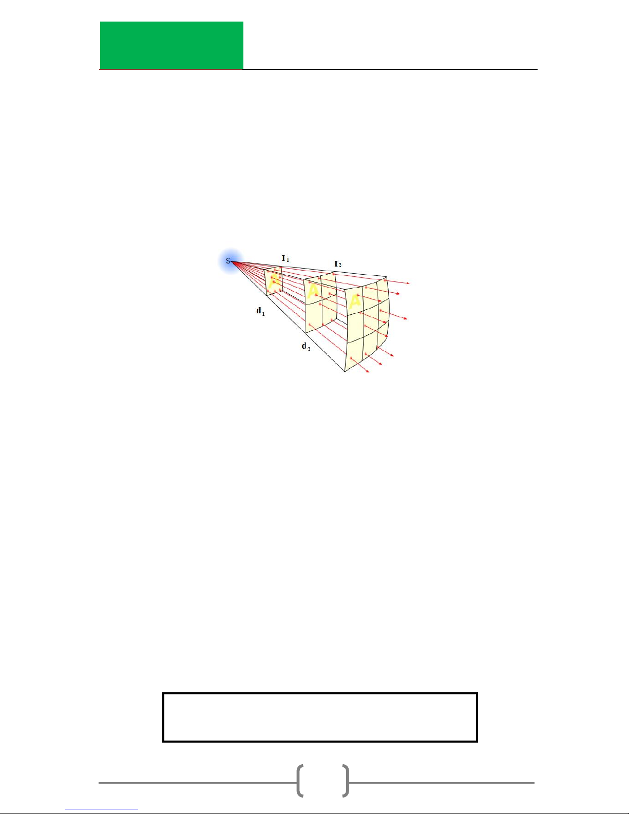
Distance
Distance is one of the most effective ways to reduce radiation
exposure. Radiation starts from a point source and as the
distance increases spreads out on a spherical surface. Its
intensity at any distance from the source depends upon the
square of the distance from the source.
I1 x (D1)2 = I2 x (D2)
2
Doubling the distance will reduce the dose rate to one/fourth.
Cutting the distance in half will increase the dose rate by four
times.
Shielding
Shielding is an effective way to reduce radiation exposure.
Alpha particles can be stopped by a single sheet of paper;
however, gamma and neutron radiation cannot be completely
stopped by shielding, but can only be reduced. Polyethylene—
which contains a very high concentration of hydrogen—is
usually used for shielding neutrons. Lead or tungsten is used for
shielding gamma rays.
MORE SHIELDING = LESS DOSE
Fig. 5.2 Distance
Page 62
InstroTek
58
Regulations
Since radioactive material can be hazardous to the public if
not used properly, its possession and use is controlled by
regulatory agencies. These are either the Nuclear Regulatory
Agency (NRC), or if an agreement state, your state agency.
License
To possess and use radioactive material, the organization,
corporation, partnership, or individual user must obtain a
specific radioactive material license. When the organization
applies for a license, it must specify the type, form, amount,
and use of the radioactive material.
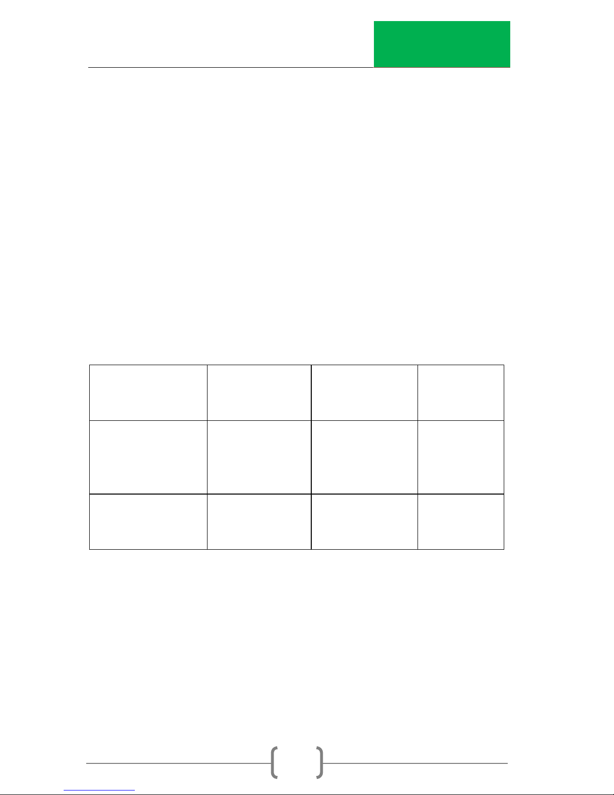
Radioactive
Material
Amount
Form
Amount
Use
Cesium-137
Sealed
Source
Not to exceed
11 mCi per
source
For use in
InstroTek
MC-3 Elite
Moisture/
Americium241/Be
Sealed
Source
Not to exceed
55 mCi per
source
Density
Gauge
The quantity specified under amount is the MAXIMUM activity
which shall not be exceeded for a single source. Furthermore,
you should ensure that the storage is adequate in space,
shielding, and restricted access for the number of gauges you
requested in your license.
The requested use should be as general as possible, since the
actual use will be limited to the specific applications stated in
Page 63

InstroTek
59
the license. Unless stated so, the gauge cannot be used to do
things like helping your child do a science projects.
Leak Testing
Portable moisture density gauges use radioactive material that
is double encapsulated in stainless steel identified as special
form. The probability of such a sealed source leaking is very
remote. To verify that the sealed source is not leaking the
gauge must be tested periodically.
A gauge should be checked upon its receipt to see that its leak
test is current and should not be used unless it is current. A new
test must be taken within twelve (12) month period. A leak test
kit has a swab or patch which is moistened, wiped around the
source area, placed in a plastic bag and then mailed to a lab
for analysis. A source is considered leaking if more than 0.005
microcurie of removable contamination is found. A copy of the
leak test certificate should be kept with the gauge and a
second copy in the RSO’s files available for inspection by the
regulatory agency. If the user has several gauges it is more
convenient if they are all tested at the same time, e.g. the first
working day of January and July.
Personal Monitoring
Dosimetry (measurement of the dose to an individual) is
required if the expected dose is 10% or more of the allowed
occupational dose of 5,000 mRem in a year. Most licensing
agencies require personal monitoring for their operators. Proper
use of a moisture/density gauge will result in a dose less than 1%
of the allowed dose, but most regulatory agencies take the
position that it may be exceeded if improperly used and thus
require dosimetry. Dosimetry is also used for long-term legal
protection to the licensee.
Page 64

InstroTek
60
Training
Persons using devices containing radioactive materials must be
trained in the safe use of the gauge by completing an
approved course offered by an organization licensed to
provide training. In some large organizations the Radiation
Safety Officer is trained and licensed to conduct the course.
When in the field, the user must have available for inspection:
Copy of the shipping papers or Bill of Lading,
Copy of the Emergency Response form with the
shipper’s emergency contact number,
Copy of Gauge Operator’s Manual,
Notify the regulatory agency of any incident or condition that
might be hazardous to the user or the public. For gauge users
this includes:
Immediate: Accident involving possible dispersement of
radioactive material, or theft, or loss. Total
Effective Dose Equivalent >5 Rem, loss of equal
or greater than one week of operations,
damage to property of greater than $200,000
24 Hour: Exposure of an individual to 5 Rem or more,
Accident resulting in the loss of one or more days
operation, or
Damage to property is excess of $2,000.
30 Day: Exposure of an individual in excess of the
allowable dose: Occupational exposure of 5
Rem, dose to embryo/fetus during entire
pregnancy to declared pregnant women 0.5
Page 65

InstroTek
61
Rem, dose to individual member of the public
0.1 Rem per year.
Safety Plan
As part of the license, each organization must have a Radiation
Safety Plan that describes procedures to be followed and what
to do in case of; fire, theft, and/or accident.
Radiation Safety Officer (RSO)
The licensee must designate some person in the organization as
the Radiation Safety Officer (RSO). The RSO is the contact point
for the regulatory agency to see that the regulations are
followed. The RSO is the person in the organization responsible
to see that safe practices are followed and that the proper
records are maintained. Designating an RSO does not relieve
the owner/officers of the ultimate responsibility.
Notice to Employees
A “Notice to Employees” is a document issued by the
regulatory agency. Normally safety problems would be
reported to the organization’s Radiation Safety Officer or a
manager. This document contains addresses and/or telephone
numbers for employees to contact if they are not satisfied with
the organization’s response.
Page 66

InstroTek
62
Transfer
The gauge should not be transferred to another party for
service, disposal, sale, or use unless the other party is authorized
to receive the appropriate radioactive material. Always
remember that the “transferor” (the licensee) has the
responsibility to obtain a copy of the “transferee’s” license or
obtain an official attestation that they are able to receive that
particular type, form, and quantity of radioactive materials.
The best way to establish authorization is to have a copy of the
other parties’ radioactive material license. Look at paragraphs
6, 7, 8, and 9, for type, form, amount, and use, and verify that
the license has not expired. The regulations provide that if the
user applies for renewal within 30 days of the renewal date, the
license is considered in “Timely Renewal” until the regulatory
agency issues a new license. If this is the case, along with the
copy of the license get a copy of the Timely Renewal Letter
from the regulatory agency or a statement from the other
party.
Temporary Storage
Use of the gauge will involve removing it from its storage
location described in the license and bringing it to job sites and
other locations to test materials. The end user is responsible to
verify requirements with the appropriate US NRC or Agreement
State regulatory agency prior to establishing a Temporary
Storage location. Normally the gauge will be returned to its
permanent storage location listed on the license each evening.
Sometimes it will be stored in temporary locations, for example,
in a trailer on a job site. This storage location should follow the
same rules for security, posting, safety, and charging as the
permanent location. If the gauge will be in the temporary
location for longer than 30 days, the regulatory agency should
be notified by letter/FAX. If it will be longer than 180 days the
Page 67

InstroTek
63
license should be amended. The gauge should not be left in
an improper storage location at the job site or in your home.
Reciprocity
Radioactive material may be used in another licensing
jurisdiction on a temporary basis. The other licensing jurisdiction
must be notified in writing at least 3 days in advance. It can be
a letter describing the device, the amount and type of
radioactive material it contains, the location the gauge will be
used, and the duration of the intrusion. Attach a copy of your
license.
If it will be for more than 180 days in any calendar year then it is
necessary to get a license in the other jurisdiction.
Service/Maintenance
Service and maintenance is a part of the Radiation Safety Plan
of any organization. Prior to each use, the integrity of the
shutter should be checked. If a source rod becomes stuck in
the transmission or exposed position, it is considered an
exposed source.
The gauge will require cleaning of the shutter block area,
depending on the type of soil and number of tests. To minimize
exposure, face the base of the gauge away from you, allowing
the body of the gauge to act as a shield when you remove the
shutter. Use compressed air or a long handled brush to clean
out the shutter area. Although the probability is very low of
there being removable contamination, there is no justification
to wipe the rod with the bare hand.
Page 68

InstroTek
64
Note: The dose at ¼ inch from the source of an exposed source
rod is approximately 70 Rem/hr.
Disposal
Radioactive material is defined as a hazardous substance. It
should not be disposed of without considering others. When the
gauge is no longer needed or useful to the organization, it is
best to transfer the ownership out of the organization. A
disposal broker such as a manufacturer may take the gauge
back for a fee. In all cases, the recipient must be properly
licensed.
Page 69

InstroTek
65
6. Transportation
This chapter covers the necessary requirements for transporting
the gauge to job sites and from one facility to another.
General Awareness
The transportation of hazardous materials is regulated by the
U.S. Department of Transportation. This includes the
transportation of the radioactive material as contained in
portable moisture/density gauges in private vehicles on public
highways. The regulations are published in the Code of Federal
Regulations, 49CFR100-177. Copies of this publication are
available from the US Government Printing Office. They are
updated in October.
Note: The regulations define any employee that is involved with
the transportation of hazardous materials, as a HAZMAT
employee, and requires that they receive appropriate training
by the HAZMAT employer. This training must take place within
90 days of hire or transfer, and must be current within three
years. The employer is responsible to maintain records of
training and testing.
Specific Functions
Shipping Name
Table 172.101 of 49CFR100-177 contains a list of hazardous
materials. The gauge contains radioactive material double
encapsulated in stainless steel capsules and designated as
Special Form. The proper shipping name selected from this list
in the table is:
Page 70

InstroTek
66
[RQ] Radioactive Material, Type A Package, Special Form, 7,
UN 3332
Special Form describes a sealed source with minimum possibility
to disburse contamination in an accident. This must be certified
by a document which is maintained on file for at least one year
after the latest shipment (e.g. the last time the gauge was
transported in the company vehicle on a public highway).
Normally it will be supplied by the gauge manufacturer. If you
have gauges from more than one manufacturer you must have
a certificate from each. A copy of an IAEA Certificate of
Competent Authority as described under International Air
Shipments can be used to satisfy this requirement. Class 7
applies to Radioactive Material. UN3332 is an assigned number
which allows quick selection in reference manuals.
Reportable Quantity
49CFR requires that shipments of quantities of hazardous
materials above certain levels are marked RQ and must be
reported to the EPA in the event of an accident that results in a
release of radioactive material. For the radioactive materials in
the gauge per 172.101 App Table 2, the reportable levels are:
Cs-137 1,000 mCi
Am-241 10 mCi
8 and 10 mCi of Cs-137 is not a reportable quantity, but 40 and
50 of Am-241 is a reportable quantity. For a reportable
quantity, RQ must be included before the description. The
shipping name label on the package must include the RQ.
Page 71
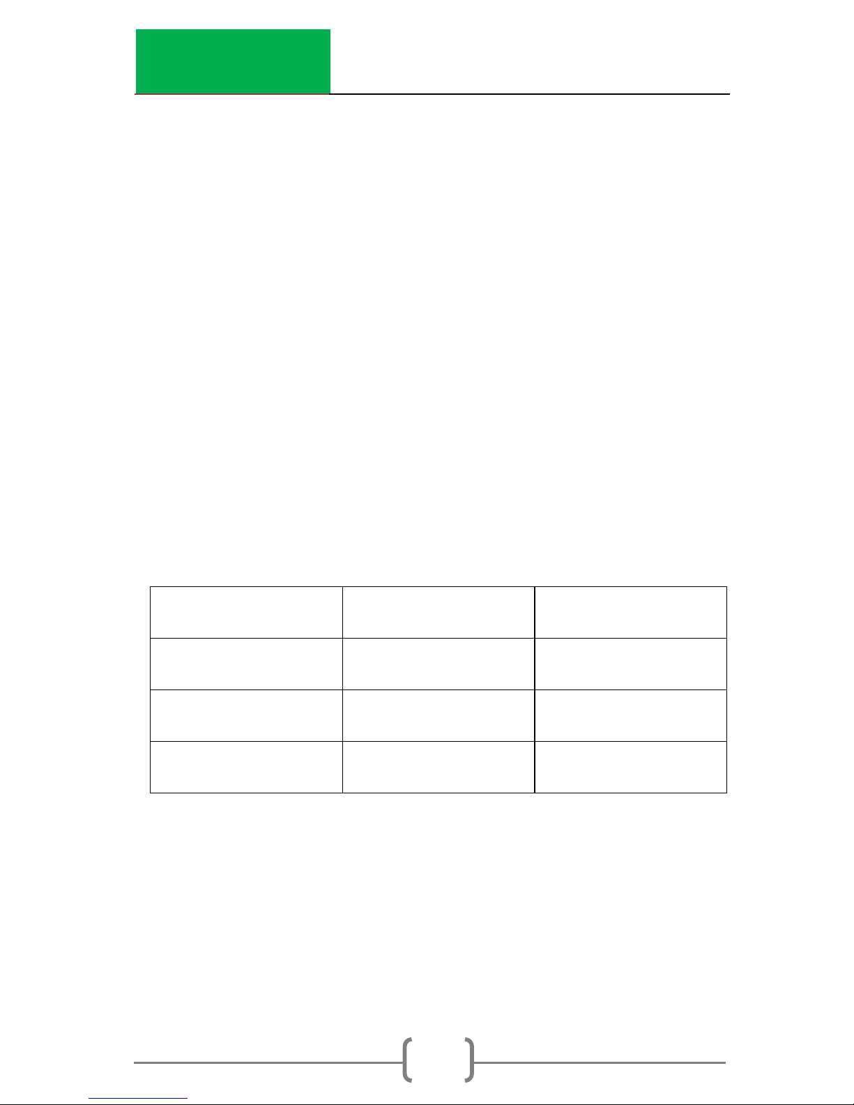
InstroTek
67
Packaging
The package the gauge is shipped in, must meet certain
requirements. For radioactive material in Special Form, a Type
A package is appropriate. The package or a prototype must
be tested and a copy of the Type A Evaluation Report and
Certificate maintained on file for at least one year after the
latest shipment. This document will normally be supplied by the
gauge manufacturer. The manufacturer must also provide a
Closure Instructions document for the Type A package. This
document should be kept in the gauge case at all times. The
Type A tests include; water spray, free drop, corner drop,
compression, and penetration test.
Labeling
A radioactive label must be selected from the following:
RADIOACTIVE
Dose rate at
package surface
Transport Index
WHITE-I
= or < 0.5 mRem/hr.
NA
YELLOW-II
>0.5 mRem/hr. to =
or < 50.0 mRem/hr.
= or < 1.0
YELLOW-III
>50.0 mRem/hr.
= or < 10.0
Fig 6.1 Various Label Dose Rates and Transport Indexes
Page 72
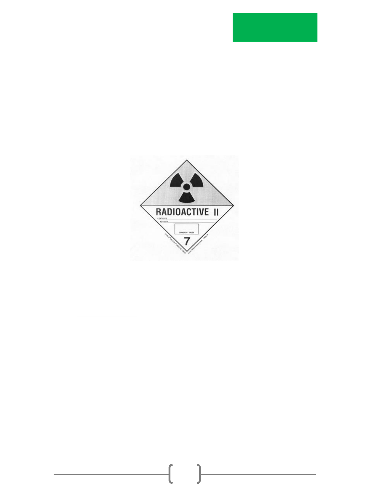
InstroTek
68
The gauge instruction manual will include a radiation profile
drawing showing dose rate measurements on the surface and
at one meter. The Model MC-3 Elite fits the RADIOACTIVE
YELLOW-II category.
RADIOACTIVE YELLOW-II labels must be placed on two opposite
surfaces. The source type, source activity, and Transport Index
entered should agree with the manufacturer’s published data.
Fig 6.2 Yellow II Label
The Transport Index is an indicator to the vehicle operator the
degree of control required. It is actually the maximum dose
rate in mRem/hr. at one meter from the package. Since it is
intended to be used by non-technical personnel, it is expressed
as a dimensionless number rounded up to the nearest 1/10th.
For multiple package shipments the driver limits the vehicle total
TI to 50. Package(s) with a TI of 1.0 or less should not be closer
to passengers than one foot. The TI for MC-3 Elite is 0.4.
Page 73
InstroTek
69
Marking
The package must be marked with the following:
Shipping Name
Package Type
Country of Origin
(International shipments)
InstroTek combines the above information on one label.
RQ, Radioactive Material, Special Form, Type A Package,
UN3332
7A TYPE A (in ½” characters)
USA
Page 74

InstroTek
70
Shipping Papers
The shipment must be accompanied by shipping papers which
include:
Name of Shipper
RQ, Description
Contents and activity in Becquerel (in parentheses)
Label Category
Transport Index
Package Type
Certification/Signature:
This is not required for a private carrier if the shipment is
not to be transferred to another party. It is easiest to
include it, just in case.
Emergency Contact:
The shipper must provide the telephone number which
must be monitored at all times the shipment is in transit
and answerable by a person knowledgeable of the
hazardous material being shipped and has
comprehensive emergency response information, or has
immediate access to a person with such knowledge.
For normal daytime work, this can be the organization’s
phone number with instructions to notify the RSO. When
returning a gauge from service or calibration, service
centers will normally supply a 24 hour number.
Page 75

InstroTek
71
Emergency Response
In addition to emergency response notification to the local
Public Health Agency for an accident involving radioactive
material, the National Response Number must be notified within
24 hours in the event of a transportation accident involving the
release of radioactive material, the death or hospitalization of
personnel, or property damage in excess of $50,000.
National Emergency Number: 800-424-8802
InstroTek Accident Emergency Number: 800-535-
5053
Preparation for Transport
1. Inspection - The gauge and package should be
checked prior to each shipment. This should include:
The gauge handle is in the shielded position and the
trigger is securely locked,
Confirmation that the shutter block is fully closed by
either a visual inspection or radiation survey,
The gauge is placed properly in the package and
that the package contains only those items which
are required to be present,
The integrity of the package, case, hinge and hasps
are in accordance with the package certificate,
All required labels and hazard markings are installed,
legible and confirmed as correct,
That the package is locked or sealed in such a way
that, while intact, will provide evidence that the
package has not been opened.
Page 76

InstroTek
72
2. Bracing - The package should be braced in the vehicle
to prevent movement during transportation or a
reasonable accident. This can be accomplished by
brackets, chain, wire rope, or cord.
3. Safety - The package should not be in the passenger
compartment. The preferred locations are the rear of a
pickup, rear of a van, or trunk of a sedan.
4. Secured - The package should be chained—or wire
roped—and locked to the bed of a pickup, locked in
the freight area of a van, or locked in the trunk of a
sedan to prevent theft. Two separate levels of security
must be used to secure the gauge during transport and
any time the gauge is not under continuous
surveillance.
5. Driving - The technician should drive in a friendly, lowprofile manner; for example, minimum lane changes.
And park in the outer area of a public parking lot.
6. Shipping Papers - The driver should have within view and
within reach (normally on the seat adjacent to the
driver) the shipping paper, and the emergency
response information sheet. To satisfy HAZMAT and other
regulatory requirements it is recommended that each
gauge have a documentation package as follows:
Bill of Lading
Emergency Response Sheet
Leak Test Certificate
Manual of operations
7. Miscellaneous - YELLOW-II does not require placarding
the vehicle. Transporting the MC-3 Elite model does not
require placarding the vehicle.
Page 77

InstroTek
73
Commercial Shipments
The previously defined requirements for private carriage
transportation apply with the following changes/additions:
1. Label Consignor/consignee:
An address label must be on the package.
2. Lock or Seal:
The package must incorporate a seal that if broken will
show improper entry
Additional requirements depend upon the mode of
commercial transportation; truck, air-domestic, and airinternational.
Truck Freight
Shipping Paper:
The shipping paper will be a Bill of Lading supplied by the carrier
and properly filled out by the shipper and emergency response
form. If more than the gauge will be shipped, the hazardous
material must be listed first. The pre-printed Bill of Lading
includes the certification. A sample Bill of Lading and
emergency response is in the Appendix.
Driver:
The driver may keep the shipping papers and emergency
response in a pocket on the driver's door, on the passenger’s
seat, but not with the hazardous material.
Page 78

InstroTek
74
Air Transport, Domestic
In the USA, shipment of the radioactive material in the gauge is
not allowed on passenger carrying aircraft. This is not a problem
since Federal Express, a cargo only airline, can transport the
gauge anywhere in the USA overnight, if requested. While it is a
domestic shipment, Federal Express has opted to follow the
requirements of the International Air Transport Association (IATA)
rather than 49CFR. This requires some changes and additional
information.
Shipping Paper:
Federal Express has a special combination document that is
both an Air Bill and a Declaration of Dangerous Goods
Document. The DG document has specific places for the
shipping information. It includes certification.
The words "Cargo Aircraft Only" must appear on the Air Bill.
The source activity must be stated in units of Bq, instead of, or in
addition to the units of mCi on the DG document. Normally the
prefix Giga (G) (x1.0e9) is used.
10 mCi (0.37 GBq)
50 mCi (1.85 GBq)
The size of the package in mm or meters must be stated on the
DG document
Page 79

InstroTek
75
Label:
The source activity must be stated in units of Bq, instead of, or in
addition to the units of mCi on the RADIOACTIVE YELLOW-II
labels.
A CARGO AIRCRAFT ONLY Label must be installed within 6” of
each of the two RADIOACTIVE YELLOW-Il labels.
Note: Pay attention to details of completing the form. Any
minor error, like leaving the title off of the signer will be cause for
rejection of the shipment. The carrier is not allowed to make
corrections.
Air Transport, International
International air shipment of radioactive material is under IATA
requirements. Most countries outside the USA will allow portable
moisture/density gauges to be carried on passenger planes.
However any international air shipments into or out of the USA
must enter or exit the USA on a cargo only aircraft.
Shipping Paper:
The shipping paper will be an Air Bill supplied by the carrier and
properly filled out by the shipper. The pre-printed Air Bill includes
the certification. A normal practice is for the shipper to supply a
Letter of Instruction, which includes the required export
declaration, to a Forwarder, who in turn completes the Air Bill.
The words "Cargo Aircraft Only" must appear on the Air Bill.
Besides the Air Bill, a Shipper's declaration of Dangerous Goods
must accompany the shipment. This form is obtainable from the
Air Carrier. It has a red "candy stripped border". Two copies are
Page 80

InstroTek
76
required. It is best to supply additional copies if more than one
carrier is involved in the routing. A sample is in the Appendix.
The source activity must be stated in units of Bq on the DG
document.
The size of the package in mm or meters must be stated on the
DG document. The DG document must cite the number of and
Certificate of Competent Authority that was obtained from the
appropriate government agency prior to the first export
shipment of the type of sources in the gauge. In the USA it is
obtained from the DOT. This document will generally be
supplied by the gauge manufacturer, which obtained them
from the source manufacture. These documents expire. Current
copies should be obtained as appropriate. Some carriers
require that copies of the cited Certificated be attached to the
DG document. Certificates of Competent Authority on file may
be used to satisfy the Special Form certification required to be
on file for at least one year after the latest shipment.
Label:
The source activity must be stated in units of Bq on the
RADIOACTIVE YELLOW-II labels.
A CARGO AIRCRAFT ONLY Label must be installed within 6" of
each of the two RADIOACTIVE YELLOW-II labels.
Page 81

InstroTek
77
7. Gauge Theory
This chapter covers the theory of operation for nuclear moisture
density gauges.
Gamma and neutron radiation and their interaction with
matter is a complex topic and difficult to cover in sufficient
details in this manual. The discussion below will be limited to the
engineering application of these radioisotope sources and their
operations in the field.
Density Measurement
Density measurement in the gauge is accomplished by using a
Cesium-137 (Cs-137) radioactive isotope and two Geiger
Mueller (GM) detectors. Density measurements are usually
accomplished in two different modes, backscatter (BS) and
direct transmission. In the backscatter mode the source and
the detector are in the same plane. In direct transmission, a
hole is formed in the material and the source rod is inserted at a
desired depth, between 2 and 12 inches (50 to 300 mm).
Cs-137 has a maximum energy of 0.662 Mev. Photons from the
source penetrate the test material and are scattered back to
the GM detector or absorbed by the material by Compton
scattering and photoelectric absorption. In the density range of
interest, the number of photons detected by the GM tubes is
inversely proportional to the material density. For example, a
given gauge at a density of 110 PCF (1760 kg/m3) will show
1500 counts; whereas, the same gauge will show a count of 700
at a density of 160 PCF (2560 kg/m3); therefore, the higher the
counts, the lower the density.
Page 82
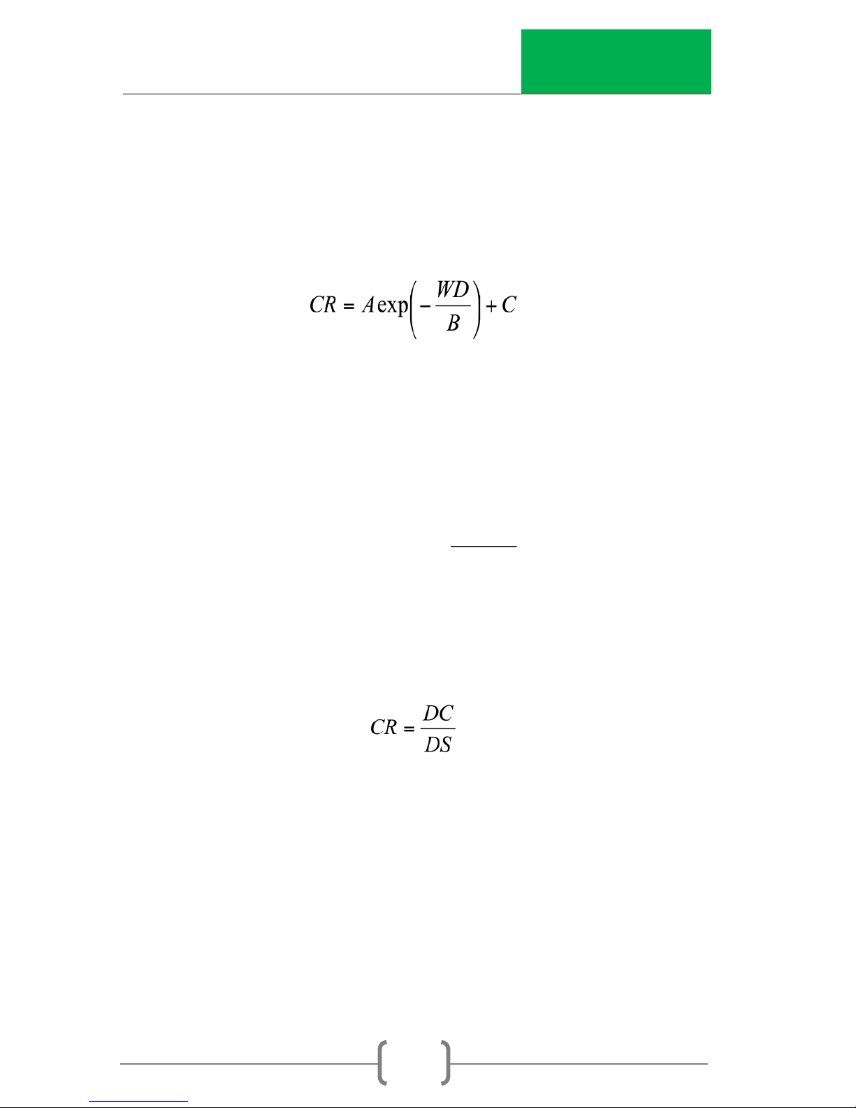
InstroTek
78
The final stage of the gauge manufacturing process is the
calibration. The density calibration method used by most
manufacturers utilizes an exponential equation that models the
relationship between the known densities and the counts.
InstroTek uses the following equation.
Where A, B and C are gauge parameters, CR is the count ratio
and WD is the material density. The A, B and C values are
commonly known as calibration constants. In the field when a
count is collected on the test material, the resulting wet density
(WD) displayed on the screen is calculated by:
Count ratio (CR) in the above equation is calculated by the
ratio of counts to reference standard counts. Test Count (DC) is
divided by Standard Count (DS).
Cs-137 has a half-life of 30 years, 2.2 % reduction in intensity per
year. The count ratio is used in this case to correct for natural
decay of the source. For this reason it is very critical that users
obtain an accurate reference standard count on a daily basis.
This will ensure that any decay in the counts is canceled by the
decay in the reference standard count. For example, six
months after calibration, the Cs-137 source will decay 1.1%
(1.1% reduction in counts). The 1.1% change will be reflected in
the test counts and the reference standard count. Ratio of
CCR
A
BWD ln
Page 83

InstroTek
79
these two counts will cancel the 1.1% effect on the counts and
will in effect normalize the counts, regardless of the date of
testing after calibration. Not using a count ratio will result in
erroneous readings, if source decay is not accounted for.
Gauge software uses the gamma count taken at the test site
and the standard count to automatically calculate and display
wet density (WD) for the material.
Moisture Measurement
Moisture measurement in the gauge is accomplished by using
an Americium-241: Beryllium (Am-241:Be) source, which emits
fast neutrons, and a single Helium 3 (He-3) tube. Neutron
measurements are always accomplished in the backscatter
mode. Both the Am-241:Be and the He-3 tube are fixed inside
the gauge base.
The average energy released by the Am-241:Be source is 4.5
Mev, with a spectrum energy ranging from 0 to 10 Mev. In the
moisture measurement process, fast neutrons from the source
interact with the hydrogen nucleus present in water and
thermalize (slow down). The thermal or slow neutrons are then
counted by the He-3 tube. Increase in water content results in
a proportional increase in thermal neutron counts detected by
the He-3 tube.
There are two assumptions made in the measurement of
moisture by neutron method. First is that any interaction
between the source and material is due to interaction with
hydrogen in the form of water. Reviewing the composition of
normal soils in the literature, the probability is very strong that
any thermalization in soils is due to interaction with hydrogen in
water. Second, that there are no elements that absorb
neutrons. However, in construction type soils, boron in some
Page 84
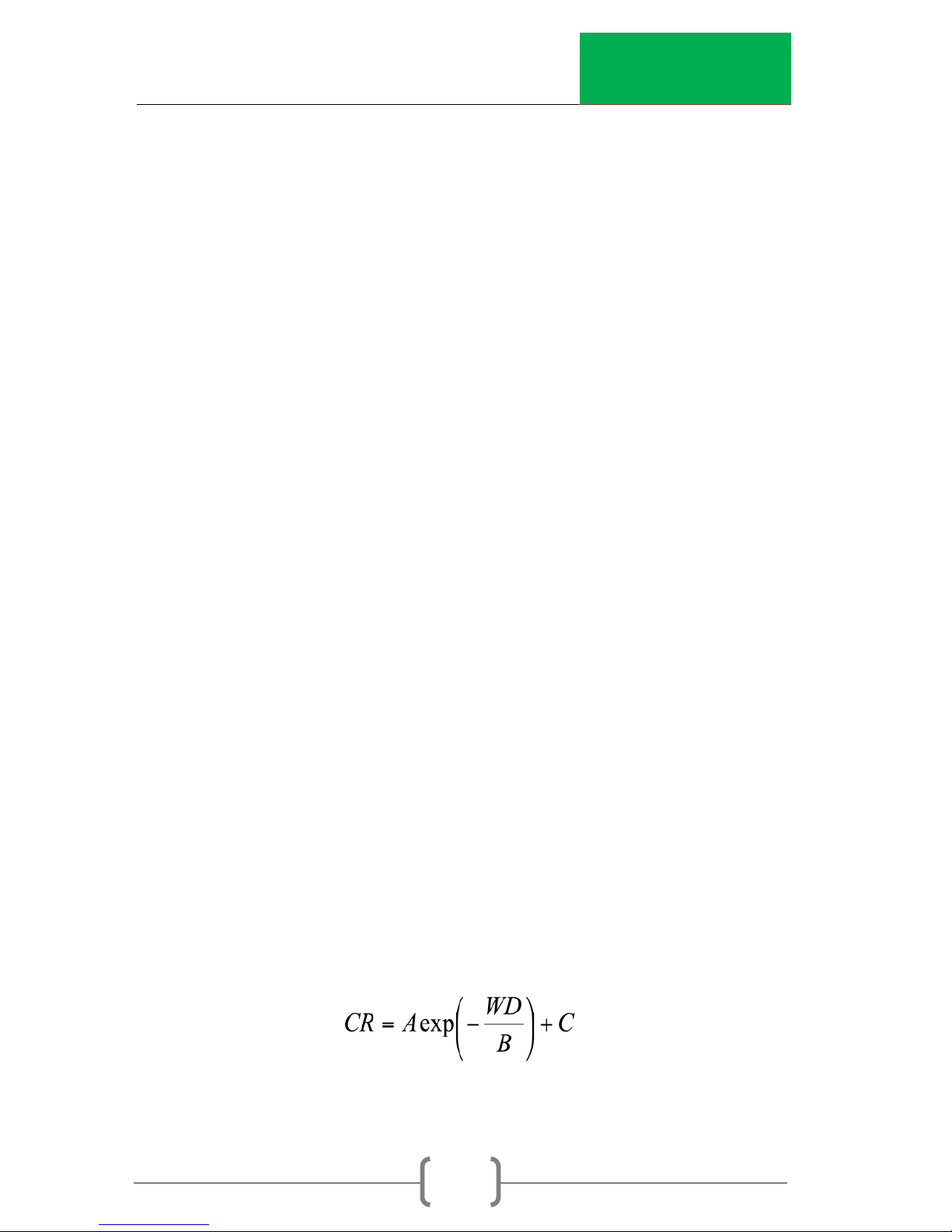
InstroTek
80
soils, chlorine in coastal soils, and iron oxide in deposits can be
encountered in sufficient concentration to affect the readings.
Gauge software contains offset features so that gauge
readings can be corrected for these influences in the field.
Depth of Measurement
In density backscatter mode, the depth of measurement is
independent of the density of the material. In backscatter
mode 85% of the density reading is from the top 2.5 inches (64
mm) of the material and the remaining 15% is from the top 2.5
to 4 inches (64 to 100 mm) of the material.
Moisture measurement depth depends on the gauge geometry
and moisture content of the material. The measurement of
moisture is heavily weighted by the material closest to the
gauge. In general a gauge with a range in moisture
measurement of 0-40 PCF (0 to 640 kg/m3); the measurement
depth is approximately 9 inches (230 mm) for soils containing 10
PCF (160 kg/m3) of moisture.
Calibration
Density Calibration - Calibration of density in the gauge is
achieved by using blocks of known density. The objective of
the calibration is to calculate the constants, A, B and C that are
used in the density equation. Once these constants are
determined, the gauge can be used in the field to calculate
wet density.
Page 85

InstroTek
81
Since the above density equation used in the gauge contains
three constants, it is necessary to use three known density
blocks at the factory to provide an original calibration. There
are many different methods of calibrating the gauge by
assuming certain criteria or by using historical data.
However, the bases of all these methods depend on having a
minimum of three different counts for three different known
density blocks.
Moisture Calibration - Gauge moisture calibration is
performed by utilizing at least two blocks of known hydrogen
density covering a range of moisture in the construction
materials. The two blocks routinely used for moisture calibration
are magnesium (0 lb./ft³, 0 kg/m3) and a combination block of
magnesium and polyethylene (~ 35 lb./ft³, ~560 kg/m³). The
gauge standard count and the counts on these blocks are
used in a linear equation such as the one below to calculate
the parameters E (intercept) and F (slope).
M= A* MCR - B
MCR is the moisture count ratio, which is the ratio of the
measured moisture count and the daily moisture reference
standard count. The daily reference standard count is
performed on a high-density polyethylene block provided with
each gauge. M is the moisture content of the material in PCF or
kg/m3. The A and B parameters are placed in the gauge
memory and are used in the field with the count ratio obtained
on the test material to calculate the moisture content from the
above equation.
Page 86

InstroTek
82
Gauge Errors
Density - There are three error parameters inherent in all gauges
manufactured: Nuclear Precision (P), Surface Roughness (SR),
and Composition Error (CE).
Precision or repeatability of the gauge is defined as the
variation in repetitive density reading on the same test spot for
a given counting time. Precision is calculated based on the
equation (P= √Count/ Slope) which depends on the number of
counts collected during a given period and the volume of the
test material measured by a specific gauge at a given depth.
Precision for a typical gauge for a one minute reading at the
time of manufacture is approximately ±0.5 PCF (8 kg/m3) at
backscatter and ±0.25 PCF (4 kg/m3) at 6” direct transmission
depth. The reduction in precision over the life of the gauge
(approximately 20 years) is insignificant.
Surface Roughness error is caused by streaming of photons
from the source to the detectors in the air space immediately
under the gauge. Surface roughness error at BS depth is much
higher than direct transmission. Surface error is usually
calculated by taking a reading with the gauge directly on
limestone block and repeating the reading on the same block
with 0.05” (1.3 mm) gap under the gauge (100% air voids). The
difference between the flush and raised reading is a measure
of the error expected from the gauge on rough surfaces, such
as open graded or base coarse asphalt. Filling the surface with
Portland cement or fine cement powder helps reduce this error,
when measurements are taken on rough materials.
Composition Error - is caused by the effect of material
characteristics on the gauge measured density. Since
attenuation of photons is effected by chemical composition of
the material, density measurements can be effected
Page 87
InstroTek
83
significantly by soils with compositions significantly different then
the references with which the gauge is calibrated. This error
indicates the amount of error you will have in your
measurements when going from one soil composition extreme
to another. Composition error is determined by measuring
limestone and granite standards with known densities.
Standards of limestone and granite that are homogenous are
available which have compositions that bracket the
composition of most soils. Composition error for nuclear gauges
is calculated by the following equation.
Lime (Gauge) and Granite (Gauge) are density of limestone
and granite standards measured by the gauge after
calibration. Lime (Actual) and Granite (Actual) are actual
density values of limestone and granite. This error indicates the
amount of error you will have in your measurement when going
from one soil composition extreme to the other.
Composition error in most gauges can be minimized by
appropriate filtering of the detection system and /or adjustment
of the source to detector distance. Even though this error can
be minimized, any adjustment to reduce this error can cause
an increase in surface error and reduction in gauge
repeatability. During design, it is extremely critical that the
gauge geometry is optimized to reduce all the above errors to
an acceptable limit.
Page 88

InstroTek
84
Moisture – The moisture source has a half-life of 430 years and
the reduction in moisture precision is insignificant over the life of
the gauge.
As mentioned in the previous sections of this manual, there are
two assumptions made in the measurement of moisture by
neutron method. First is that any interaction between the
source and material is due to interaction with hydrogen in the
form of water. Second, that there are no elements that absorb
neutrons. However, in construction type soils, boron in some
soils, chlorine in coastal soils, and iron oxide in deposits can be
encountered in sufficient concentration to affect the readings.
Also, variation in bound hydrogen in clay soils can cause
significant errors in gauge moisture readings and have to be
corrected for under the offset functions in the MENU.
Gauge software contains offset features to account for some of
these errors in the reading. Refer to the Menu functions for
more details on how to correct your gauge readings using
offset functions.
Page 89

InstroTek
85
8. Routine Maintenance and
Troubleshooting
This chapter covers routine maintenance items such as leak test
procedure, routine maintenance of gauge components, and
troubleshooting hints.
Leak Test Procedure
Leak test is required by your license and shall be performed at
least once every twelve months (1 year), unless indicated
differently by your license. To conduct a leak test on MC-3 Elite,
follow the below procedure:
1. Place the gauge in safe position.
2. Remove the four screws from the front panel
and lift the panel.
3. Locate the radiation label in the bottom of the
gauge.
4. Using InstroTek Leak Test Kit, moisten one swab
from part number 520.7200,
5. Wipe the radiation label with the swab.
6. Replace the front panel and tilt the gauge on its
side.
7. Use the swab and wipe around the source rod
opening under the gauge.
8. Place the swab in the plastic bag included with
kit.
9. Record the gauge and source information on
the form included with kit.
10. Package the swab and the information form
and mail to InstroTek for analysis.
11. Tighten the four screws on the front panel and
store the gauge.
Page 90

InstroTek
86
Routine Maintenance
Radiation sources
The MC-3 Elite contains two radioactive sources. The sources
require no maintenance. The small Americium-241:Beryllium
source is in the center of a lead cup. The source is inside a lead
cup which screws into the shielded area in the center of the
gauge base. Do not attempt to remove this source. The Cesium137 is inside the end of the source rod which is inside the guide
tube. The source is fixed inside the tip of the source rod. In the
safe position (source rod handle at the top of the guide tube
marked “safe”) the Cs-137 source is surrounded by lead and
tungsten shielding. Do not attempt to remove this source from
the source rod.
Bottom Plate
Maintenance in the bottom plate area of the gauge may be
required if the following problems are encountered while using
the gauge. Difficulty in lowering or raising the source rod when
pulling the handle up or down, and/or unusual density counts.
These are generally an indication that soil or other material has
migrated into the bottom of the gauge and it needs to be
cleaned and fresh grease added.
Important: InstroTek recommends use of only MagnaLube G as
a greasing agent in this gauge. MagnaLube has Teflon filler,
which provides superior and longer lasting performance in the
environment these gauges are typically used.
MagnaLube G is a trademark of SaundersEnterprises, Inc.
Teflon is a trademark of DuPont Company.
Page 91

InstroTek
87
Procedure
1. With the source rod in the “SAFE” position, place
the gauge on its side with the bottom plate to
your right or left. (This positioning will prevent
unnecessary radiation exposure to the operator.)
2. Examine the bottom plate. Clean the screw
heads if necessary to make removal easier and
to prevent the screw heads from stripping.
3. Use a Phillips screwdriver to remove the bottom
plate. It is normal to see evidence of wear,
however if deep grooves are present where the
sliding block slides, it may indicate that the plate
needs replacement. There should be a scraper
ring in the bottom plate hole where the source
rod extends; if the ring is worn or missing call
InstroTek for a replacement.
4. If a large amount of dirt has accumulated in the
cavity above the bottom plate, the scraper ring
has become worn and should the replaced.
Replace the scraper ring by removing the
retaining ring with a small screwdriver. It is
recommended that the scraper ring be
changed at least once a year or more often
depending on the use. The scraper ring can be
pushed out. Clean the entire plate of any debris
and install a new scraper ring and retaining ring.
Add a thin layer of grease where the sliding
block slides.
5. To remove the sliding tungsten shield, use a
screwdriver to pull the shield out by the spring.
Page 92

InstroTek
88
Remember to stand to the side with the source
rod in the safe position. Use a screwdriver and
rag to remove debris form the sliding block
cavity.
Caution: Do not use your hand to clean this area.
Clean the sliding block and spring, add a thin layer of grease to
the sides, top, bottom, and angle of the block; reinstall. Make
sure the end of the spring is centered in the spring holding
support so the sliding block moves straight in and out.
Source Rod Bearings
1. The source rod bearings will need periodic
lubrication with MagnaLube. Indications of this
are difficulty in moving the rod up and down or
binding of the rod. Add MagnaLube to the swab
and swab the source rod at the point of entry
into the gauge.
Cleaning
Most of the gauge cleaning should be done with a mild
cleaner such as 409 or a citrus based cleaner like GooGone.
We do not recommend using fuels (gasoline or diesel) or oils to
clean the gauge as these chemicals can damage plastic,
rubber, and synthetic materials. If the aluminum gauge bottom
becomes coated with asphalt, WD-40 or GooGone will remove
the asphalt. Keep the liquefied asphalt away from the plastic
surfaces and gaskets. Be sure to wipe off residue before putting
the gauge back in use.
Page 93
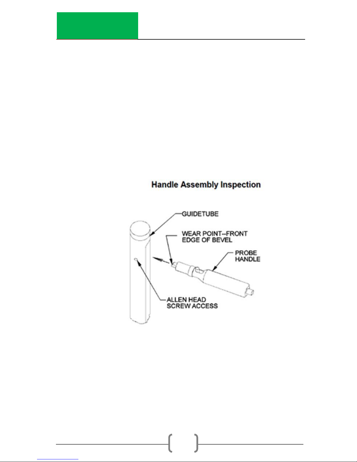
InstroTek
89
Handle Assembly Inspection
Inspect the handle assembly monthly for wear.
1. Set Handle in BS position
2. Loosen 5/32” in Allen head hex screw on side of
guide tube ONLY until handle is free. Do not
remove screw.
3. Pull Handle away from guide tube.
4. Check beveled front edge of handle latch for
excessive wear.
Fig. 8.1
5. Check notches inside guide tube for excessive
wear.
Page 94
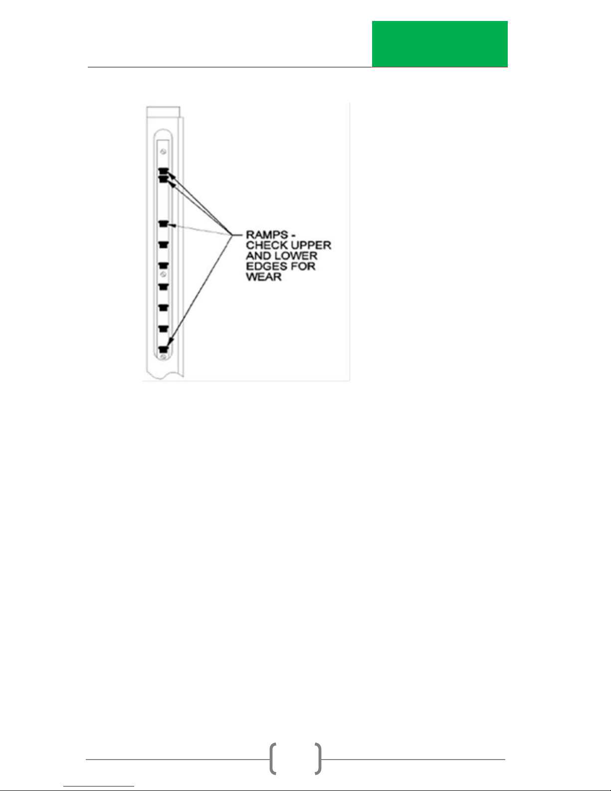
InstroTek
90
Fig 8.2
6. Reassemble handle to guide tube assembly and
Tighten the Allen screw.
Note: If wear on the notches or latch appears to be excessive,
contact your CPN-InstroTek service representative for
assistance.
Page 95
InstroTek
91
Troubleshooting
Symptom
Probable Cause
Gauge does not power on
1. Dead batteries, recharge or
change batteries
2. Gauge inside is wet, dry the
interior of the gauge
3. Ribbon cable inside the
gauge is defective or not
connected
4. Keypad is defective
Density readings are incorrect
1. Check calibration constants
2. Check standard count
Counts are erratic
1. Circuit problem, contact
InstroTek
Page 96
InstroTek
92
9. Specifications and Appendices
Specifications:
National and International
Standards
ASTM D6938, D2950, D7013,
D7759, C1040; AASHTO T310
Density Measurement Range
1120 to 2720 Kg/m3 (70 to 170
lbs./ft
3
)
Moisture Measurement Range
0 to 640 Kg/m3 (0 to 40 lbs./ft
3
)
Density Source
Cesium 137
Moisture Source
Americium 241: Beryllium
Density Source activity
0.37 GBq, 10 mCi
Moisture source activity
1.85 GBq, 50 mCi
Transport Index (TI)
0.4 mRem
BS Precision at 2000 Kg/m
3
7.8 kg/m3 (0.49 lbs./ft
3
)
Direct Transmission Precision at
2000 Kg/m
3
3.5 kg/m3 (0.22 lbs./ft
3
)
Moisture Precision at 240
Kg/m
3
4.42 kg/m3 (0.28 lbs./ft
3
)
Composition Error BS
16 kg/m3 (1.0 lbs./ft
3
)
Composition Error Direct
Transmission
13 kg/m3 (0.8 lbs./ft
3
)
Surface Error BS
48 kg/m3 3.0 lbs./ft
3
)
Surface Error 150 mm (6")
depth
16 kg/m3 (1 lbs./ft
3
)
Backlight Display and Keypad
Yes
Internal Temperature
Monitoring
Yes
Shielding Materials
Lead, Tungsten, and
Cadmium
Top Shell
UV stabilized plastic
Batteries
6 NiMH AA rechargeable and
one 9v Alkaline backup
battery
Base and tower
Aluminum
Source Rod
Stainless Steel
Guide Tube
Aluminum
Operating Temperature
Page 97
InstroTek
93
(ambient)
-10° to 70° C (14° to 158° F)
Maximum Surface
Temperature
170° C (338° F)
Gauge Size
67.8cm x 35.8cm x 24.8cm
(26.7"x14.1" x 9.75")
Weight
13Kg (28.5 lbs.)
Shipping Weight
40 Kg (90 lbs.)
Page 98

InstroTek
94
Appendix 1: Sample Bill of Lading
Bill of Lading
Shipper:
ABC Company, Inc.
1234 John Smith Rd
Raleigh, NC 27617
RQ, UN 3332, Radioactive Material, Special Form, NON FISSILE
OR FISSILE
EXCEPTED, 7
Type “A” Package, Containing:
Cs-137, 0.37 GBq (10 mCi)
Am-241:Be, 1.85 GBq (50 mCi)
Radioactive Yellow II Label, TI=0.4
******EMERGENCY CONTACT******
1-800-535-5053
Shipper
________________________________________________
(Signature)
Page 99

InstroTek
95
Appendix 2: Emergency Response Information
Nuclear Gauge Emergency Response Information for
Transportation
Reference DOT ERG 2016 pg 266-267 Guide 164, and 49CFR
Potential Hazard
1) Proper Shipping Name
UN3332 Radioactive Material Type A Package, Special
Form, 7, RQ
2) Health Hazards
Radiation presents minimal risk to transport workers,
emergency response personnel and the public during
transportation accidents. Packaging durability increases
as the potential hazard of radioactive content
increases.
Undamaged packages are safe; contents of damaged
packages may cause external radiation exposure and
much higher external exposure if contents (source
capsules) are released.
Contamination and internal radiation hazards are not
expected, but not impossible.
Packages (cartons, boxes, drums, articles, etc.)
identified as “Type A” by marking on packages or by
shipping papers contain non-life endangering amounts.
Radioactive sources may be released if Type A
packages are damaged in moderately severe
accidents.
Type B packages, and the rarely occurring Type C
packages, (large and small, usually metal) contain the
most hazardous amounts. They can be identified by
package markings or by shipping papers. Lifethreatening conditions may exist only if contents are
released or package shielding fails. Because of design,
evaluation, and testing of packages, life endangering
Page 100

InstroTek
96
releases are not expected in accidents except those of
utmost severity.
Radioactive White-I labels indicate radiation levels
outside single, isolated, undamaged packages are very
low (less than 0.005 mSv/h (0.5 mRem/hr)).
Radioactive Yellow-II and Yellow-III labeled packages
have higher radiation levels. The transport index (TI) on
the label identifies the maximum radiation level in
mRem/h one meter from a single, isolated, undamaged
package.
Radiation from the package contents, usually in durable
metal capsules, can be detected by most radiation
instruments.
Water from cargo fire control is not expected to cause
pollution.
3) Fire or Explosion
Packaging can burn completely without risk of content
loss from sealed source capsule.
Radioactivity does not change flammability or other
properties of materials.
Radioactive source capsules and Type B packages are
designed and evaluated to withstand total engulfment
in flames at temperatures of 800°C (1475°F) for a period
of 30 minutes.
Public Safety
CALL EMERGENCY REPSONSE Telephone number on
Shipping Paper first. If Shipping Paper is not available or
there is no answer, refer to the appropriate telephone
number listed on the inside back cover of the DOT
Emergency Response Guidebook.
EMERGENCY RESPONSE PHONE #:1-800-535-5053 (US & Canada)
1-352-323-3500
 Loading...