

CPN MC3 ELITE, MC-1 Elite Operating Manual
www.InstroTek.com
CPN MC3 ELITE
™
Moisture/Density Gauge
OPERATING MANUAL

‘This page may be removed from the
manual to prevent the unauthorized
access to the restricted menu functions of
the InstroTek/CPN MC-3 Elite.’
Restricted Menu Function
Access Code:
3548
Please note up to 2% of the mechanical components used in the gauge may
be recycled material.

This page may be removed from the
manual to prevent the unauthorized
access to the restricted menu functions of
the InstroTek/CPN MC-3 Elite.

© 2018 InstroTek, Inc.
MC-3 Elite Moisture/Density Nuclear Gauge
Operation Manual Version 4

InstroTek
1
1. Table of Contents
****************************************
1. INTRODUCTION AND GAUGE COMPONENTS 2
2. GETTING STARTED 4
3. MENU FUNCTIONS 25
4. RADIATION THEORY 47
5. RADIATION SAFETY AND HEALTH PHYSICS 53
6. TRANSPORTATION 65
7. GAUGE THEORY 77
8. ROUTINE MAINTENANCE AND TROUBLESHOOTING 85
9. SPECIFICATIONS AND APPENDICES 92
10. INDEX 101
11. WARRANTY 110

InstroTek
2
1. Introduction
Thank you for your purchase of the InstroTek/CPN Model MC-3
Elite. InstroTek/CPN has been a world leader in the
development and implementation of nuclear gauges for over
45 years. InstroTek/CPN design and manufacture gauges used
in variety of applications such as agriculture and irrigation
control, coal density and moisture determination, moisture in
pipe insulation and many more.
The Elite gauge was designed to meet the demands of the
construction market with reliability, accuracy and reduced
costs. It is designed to reduce the daily field effect of moisture
and dust, providing enhanced reliability and accuracy in all
rugged construction environments.
The software features are easy to follow. The four line display
provides large characters and intuitive instructions to help the
operators navigate through the different functions. The
diagnostics features allow the operators diagnose problems on
the field, increasing the gauge testing productivity.
Our technical staff includes some the most experienced
nuclear moisture/density gauge developers and engineers in
the world. We believe you will be impressed with the MC-3
Elite and its functionality.
We will provide you with a superior gauge, unmatched
expertise, and exceptional service.

InstroTek
3
Model MC-3 Elite and Standard Accessories
Model MC-3 Elite
1. MC-3 Elite
2. Reference standard block
3. Scraper plate
4. Extraction tool
5. Drill rod
6. Type A shipping case
7. AC and DC charger, one each
8. Manual of operation and gauge paperwork
9. Gauge and Case Lock, one each
8
6
Fig 1.1 MC-3 Elite Nuclear Gauge & Accessories
1
2 3 4
5
7
9
9
1

InstroTek
4
2. Getting Started
Before using this gauge, it is recommended that the user read
this manual and understand the operation of the gauge.
Operating your Model MC-3 Elite
This chapter covers the basic operation of your gauge from
powering on to taking a measurement. This manual should also
be used for Smart-MC electronic upgrade to older MC1 DRP
and MC3 gauges.
Important: In order to use this gauge, the operator is required to
meet and understand the provisions of the radioactive
materials license under which he/she is authorized to operate
this gauge.
Charging the Batteries
When the gauge is powered on, check for the low battery
warning (“N” or “NA” displayed). If the low battery warning
does not appear on the display, the gauge is ready for use and
does not require additional charge.
The MC-3 Elite contains 6 welded AA NiMH batteries. The
batteries are charged at the factory prior to calibration. Life of
rechargeable batteries depends on the number of
charge/discharge cycles. For best results, only charge your
batteries, when the battery low warning is displayed. The
gauge will display an “N” in the top right when the battery is
getting low. The gauge will display “NA” when the NiMH
batteries have been drained and the gauge has switched to
the alkaline backup.
The provided DC charger can be used for emergency charging
in the field. Plug this charger into your vehicle charger outlet
and charge the gauge for 30 minutes. This should provide
enough battery power to your gauge to complete your testing

InstroTek
5
for the day. Charge the gauge overnight after the day of
operation.
During a charging session a “C” will appear in the upper right
hand corner of the display. The gauge is designed with a
SmartCharge chip that prevents the battery from over
charging.
The gauge cannot be turned off while the unit is being charged.

InstroTek
6
Powering the Gauge On
Use the ON/YES key to power the gauge on. When the gauge
is powered on the CPN Elite will go through the following SelfTest screens:
Self-Test will take approximately 15 seconds and checks for
proper operation of the keypad, density and moisture
detectors, and the High Voltage. Place the gauge on the
standard block during self-test.
The Gauge will go to the Ready display after a successful SelfTest. If a failure is detected during Self-Test, one or all of the
following messages will display on the screen.
1. Keypad Test Failed - This indicates a faulty keypad or a
stuck key. Pressing any key on the keypad during this test
will display this error. If a key is pressed by mistake during
this test, simply restart the gauge by powering off and then
on again. However, if the error is displayed again, contact
your InstroTek representative.
2. He-3 Tube Failure - If the gauge is on the reference
standard block during self-test, then there is a potential
problem with the electronics or the He-3 tube. If the gauge
is not on the reference standard block, place it on the
reference standard block and repeat this test. Contact
your InstroTek representative if this error is repeated;
3. GM tube failure - This indicates if one or both GM tubes are
not operational. Contact your InstroTek representative.
CPN Elite
Version: #. ##
High Voltage Test
Calibration
Reminder

InstroTek
7
4. High Voltage Failure - This indicates the high voltage
module is not working properly.
Important: It is suggested to always power the gauge on and
allow the self-test to complete before leaving for a job site.
Place the gauge on the reference standard block and check
the results of the Self-Test and ensure there are no failures.
Charge the batteries if needed by the provided AC or DC
charger (Refer to the section on Charging Batteries).
Note: To preserve battery life for extended gauge operations,
the gauge will go into a shutdown mode if no key is pressed in
one hour. Simply press the ON key when you are ready to start
again. The gauge will not run the Self-Test if shut down was due
to an automatic one hour ‘inactive gauge shut down’ feature.

InstroTek
8
Setting Units of Measurement
The default for the gauge is lb. /ft3 (PCF). You may change the
units to kg/m3 or g/cc by completing the following steps.
Press the MENU button, the first screen will be:
Scroll DOWN 5 screens
Press 12, (button 1, then 2)
Use the number buttons to select 1 for PCF (pounds per cubic
foot), 2 for kg/m3, or 3 for g/cc.
After selecting the Unit of Measurement, the Elite returns to the
menu screen.
11. Auto Scroll
12. Set Units
Up/DOWN FOR Next
Select3, ESC Exit
1. PCF
2. kg/m3
3. GCC
Select#, ESC Exit
11. Auto Scroll
12. Set Units
Up/DOWN FOR Next
Select#, ESC Exit
1. Recall
2. Set Depth
Up/DOWN FOR Next
Select#, ESC Exit
InstroTek
9
Press ESC to return to the gauge ready screen
Setting Test Time
The gauge provides four different testing times: 15 seconds, 30
seconds, 1 minute, and 4 minutes. The gauge precision
improves with increased test time. In general, a one minute
count will result in a precision that is two times better than a 15
second count and a four minute count precision is twice as
good as a one minute count. Refer to your local specifications
for selection of an appropriate testing time.
Press the TIME button on the front panel.
Scroll UP or DOWN to set a desired count time (15 seconds, 30
seconds, 1 minute, or 4 minute)
Press YES when you have chosen the time. You will be returned
to the gauge ready screen.
GAUGE READY
COUNT TIME: 1 min.
Depth: BS OFFSET: N
02/16/2013 12:07 PM
Cnt Time: 15 sec.
UP/DOWN TO CHANGE
YES TO ACCEPT
ESC to Exit
GAUGE READY
COUNT TIME: 1 min
Depth: BS OFFSET: N
02/16/2013 12:07 PM

InstroTek
10
Measurement Depth
The Elite gauge is designed and is equipped with an automatic
non-contact magnetic depth indicator. The depth is
automatically read as you lower the source into measure
position and the appropriate constants are selected for
calculation of density.
The gauge can be placed into manual depth mode by
disabling the Automatic depth mode from the MENU functions
Taking a Daily Standard Count
It is important that a minimum of one daily standard count is
taken at each job site. The moisture standard count should be
within 2% and density standard count should be within 1% of the
average of the previous four standard counts. If the average of
the previous four standard counts is taken more than three
months from the current standard count, take four new
standard counts and generate a new average for comparison.
Check the density standard count and ensure it is within the
range of the expected standard count provided with the
calibration paperwork.
The standard count is used to correct for decay in the
radioactive source, especially for the Cs-137 density source.
Keeping a log of the daily standard counts is a good indicator
of gauge operation from day to day. Elite will store the last 30
standard counts in its memory. They can be recalled and
reviewed from the MENU functions. To obtain the most
representative standard count in the field, allow the gauge to
stabilize to the field environment for a minimum of 15 minutes.
Remember the following steps, when taking standard counts:
1. Find a level location close to the test site and
setup your polyethylene reference standard
block.
InstroTek
11
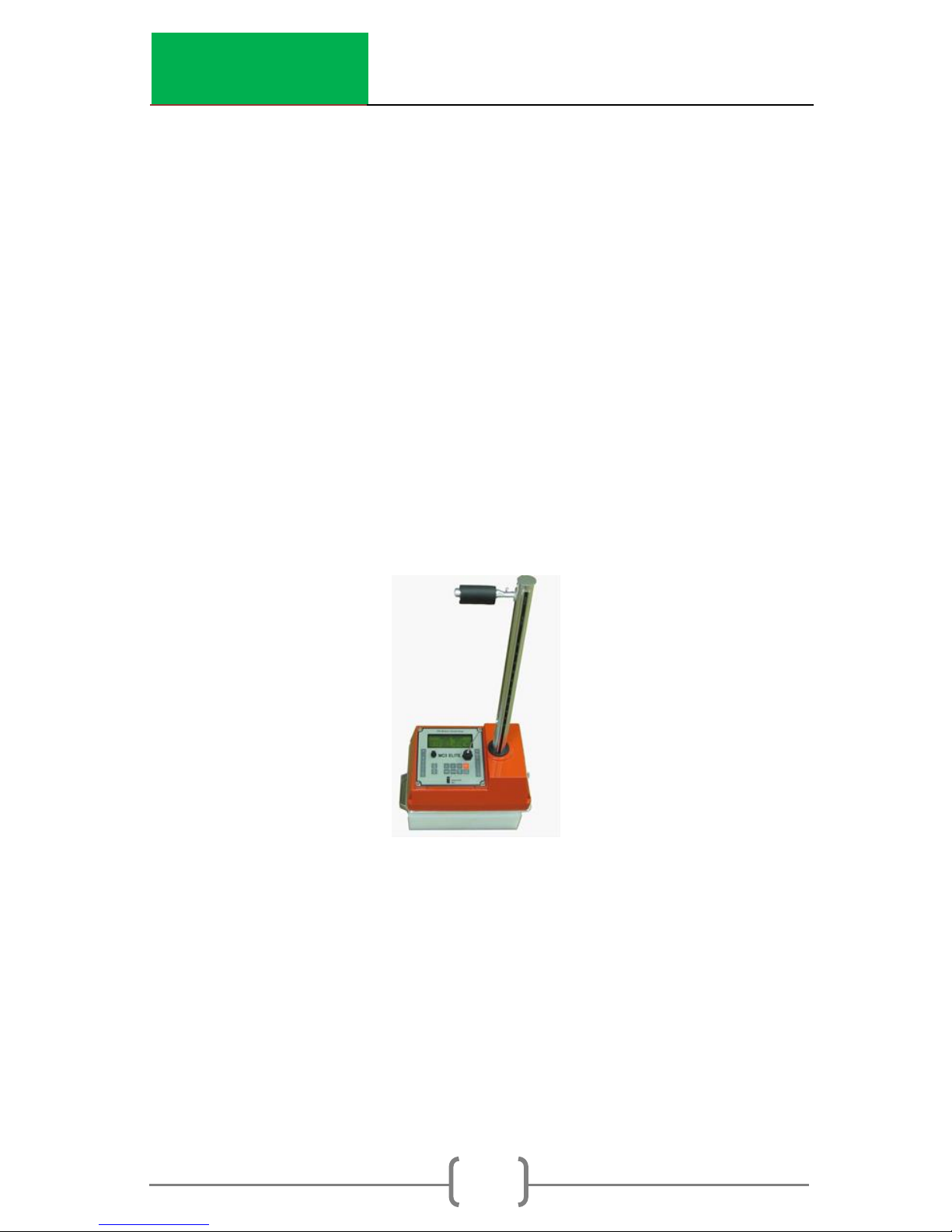
2. Place the gauge on top of the standard block on
a level surface; the keypad end of the gauge
should be pushed against the metal butt plate.
See Fig 2.1.
3. Ensure the reference standard block is placed on
a dense material, such as soil, asphalt, or
concrete. Do not take standard counts on truck
tailgates, tables, or non-solid floors.
4. When you place the source rod in the “SAFE”
position notch, gently tap it down without pulling
the trigger to make sure the handle plunger is
properly seated inside the notch. Ensure the
handle is reasonably parallel with the gauge.
Fig 2.1 Reference Standard Count Position

InstroTek
12
Press the STD button on the front panel. The Standard Count will
display with your previous standard count.
Press the ON/YES button to take a new count or press OFF/NO
to cancel and go to the gauge ready display.
Press the START/ENTER button. In Auto Depth mode, if the
source rod is not in the Safe position, the gauge will display a
message indicating “Depth not at Safe Position”
The time will begin to count down from 240 seconds (4 minutes).
After 240 seconds the results of your standard count will be
displayed
DS= ###
MS= ###
Take New Std Count?
Press YES or NO
Place Gauge on Poly
Std. Block in SAFE
Position
Press Start
Standard Count
Time: 240 sec.
DS= ###
MS=###
Use New STD CNT?
Press YES or NO

InstroTek
13
DS is the density standard count and MS is the moisture
standard count. Log these numbers into your Daily Standard
Log Record (notebook), and then press the ON/YES button
The gauge ready screen will appear and you are now ready to
begin testing.
Note: If there are no standard counts in the gauge, a message
will display indicating “Invalid Std”. Take a new standard count
prior to testing.
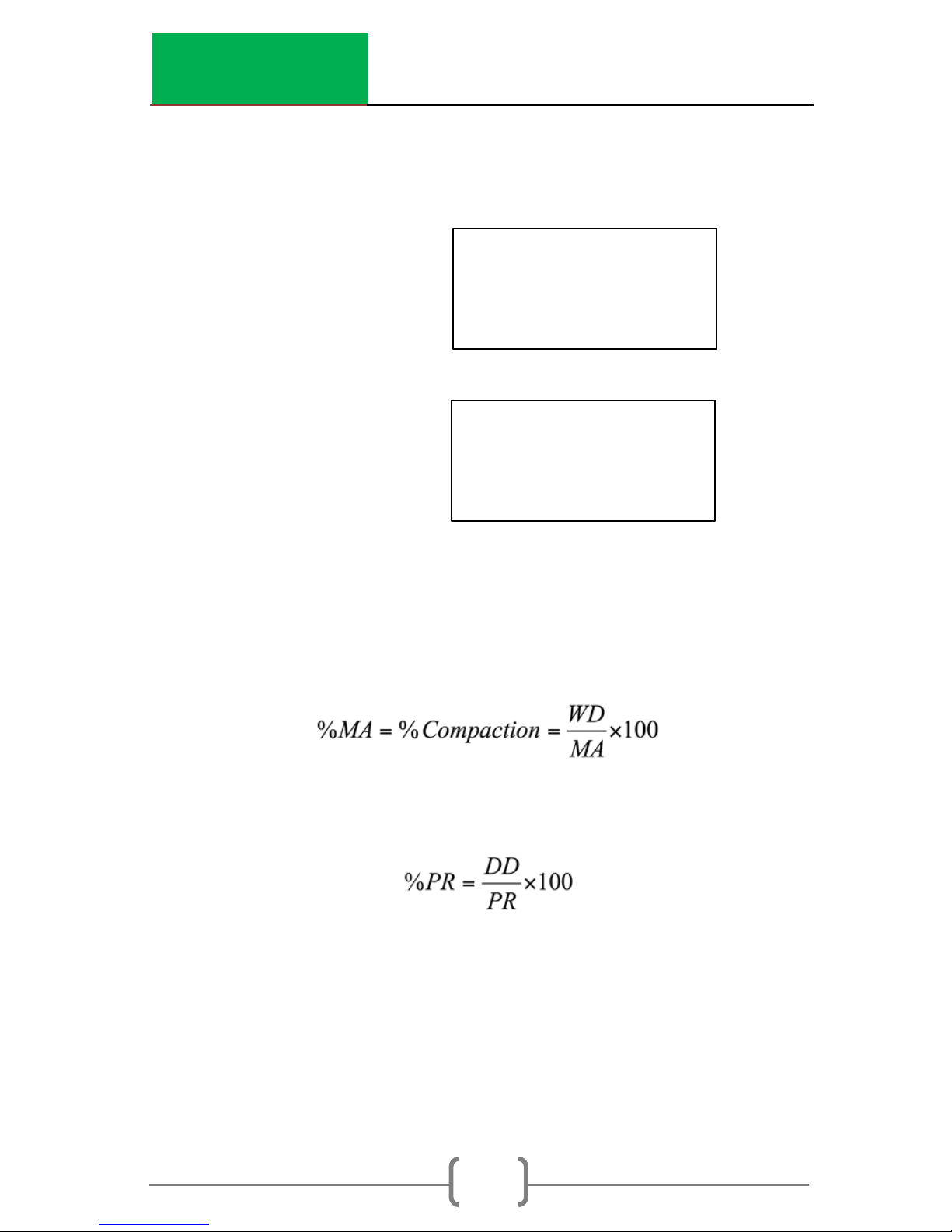
Setting Target/Laboratory Density Values
The gauge is capable of calculating and displaying percent
compaction based on user defined laboratory values. Pressing
the MAX/PR button allows the laboratory value to be entered.
Select PR (Proctor) for soil/aggregate materials and Max. Dens.
(Marshall or laboratory max (rice) density) for percent
compaction on asphalt materials. Soil Specific Gravity (SG)
(which is used to calculate % Soil Air Voids) can also be
entered. %MAX, %PR, and %Soil AV will be calculated and
displayed automatically after each measurement.
Press the MAX/PR button.
1. Proctor
2. Max. Dens
3. Soil SG

InstroTek
14
Press 1 for setting soil target value PR (Proctor), and
Press 2 for setting asphalt target value MAX (Max. Dens.).
Press 3 for setting soil specific gravity (SG).
Proctor
Press the ON/YES button
Once the PR value is entered, the gauge ready screen will
display.
Max Dens.
Press the ON/YES button
PR: #### PCF
Change value?
Press YES or NO
ESC to Exit
Enter Value For
Proctor: ### PCF
ENTER to Accept
ESC to Exit
MA: #### PCF
Change value?
Press YES or NO
ESC to Exit
Enter Value For
Max. Dens: ### PCF
ENTER to Accept
ESC to Exit
InstroTek
15
Once the MA value is entered, the gauge ready screen will
display.
Soil SG
Press the ON/YES button
Once the SG value is entered, the gauge ready screen will
display.
Equations used by the gauge
Where: WD (Wet Density) is measured by the gauge.
Where: DD (Dry Density) is calculated by the gauge. M
(Moisture) content is in PCF.
DD= WD - M
Soil SG: #### PCF
Change value?
Press YES or NO
ESC to Exit
Enter Value For
Soil SG: ### PCF
ENTER to Accept
ESC to Exit

InstroTek
16
% PR can also be used to determine % Solids, if the “void-less
density” of the material can be determined.
Where: DD is the dry density in g/cm³, SG is the soil specific
gravity provided by the user, and M is the moisture content in
g/cm³.

InstroTek
17
Site Preparation (soil, aggregates, and granular
materials)
1. Locate a test site away from other gauges and large
objects that could influence the gauge results. These
items include your truck, large concrete barriers or walls.
If the test site is required to be near or close to walls,
then refer to the special functions section, Offset and
Trench Correction.
2. Using the edge of the scraper plate provided, level the
test surface by removing raised areas and voids. If there
are any small voids that weren’t filled, use some
surrounding local soil or material to bring them up to
grade.
3. Place the extraction tool provided with the gauge over
one of the guides on the scraper plate.
4. Place the drill rod provided with the gauge into the
same guide as the extraction tool.
5. With a hammer of about 4-8 lbs., drive the drill rod into
the surface of the grade.
Caution: Eye, hand and shin protections must be worn
while forming a hole in the surface.
The drill rod has 6 notches spaced 2” apart, which are
numbered for the depth of the reading. These numbers
show the depth necessary to drive the rod for a
particular gauge depth reading. The rod depth
indicators automatically adds 2” extra depth to the
hole, which is necessary for accurate readings.

InstroTek
18
6. Removal of the drill rod should be done in a manner
that will not damage the hole. Using a twisting motion,
pulling straight up on the drill rod might be the best way
to extract the rod from the material. Care must be
taken to preserve the integrity of the hole. Collapsed or
larger than required holes can negatively influence your
readings.

InstroTek
19
Site Preparation (Asphalt)
1. Locate a test site away from other gauges and large
objects that could influence the gauge results. These
items would include work trucks, large concrete barriers
or walls.
2. For coarse, open graded mixtures, fine fill material, such
as Portland cement or fine sand, should be used to fill
the voids, but taking care not to completely cover the
surface of the asphalt. The gauge base should be
resting on the asphalt not the filler.
3. After the gauge has been placed on the test site, rock
the gauge back and forth by pressing on opposite
corners. Minimizing the amount of rock will ensure the
most accurate results achievable in the field.

InstroTek
20
Taking Measurements
Lower the source rod to the desired depth by pulling the
handle trigger back and pushing down on the handle. In
positions of measurement, always ‘lock’ in to the position by
allowing the trigger to engage the notch and then gently
pushing the handle down to ‘seat’ on the notch.
Caution: Never drive the source rod into the soil by hammering
the gauge handle down.
To start measurement, press START/ENTER. The gauge will then
begin taking counts.
After the gauge has completed its count time, it will display:
Depth: BS
Time: 15 sec.
If you exit out
of the results
information,
you can use
the Recall
function
under menu
to retrieve
your results.
M Count: ##
D Count: ##
MCR: ### DCR: ###
Press UP/DOWN
WD: #. # PCF
%MA: #. #
%Voids: #. #
Press UP/DOWN
Moist: #. # PCF
# DD: #. # PCF
%Mois: #. #%PR: #. #
PRESS UP/DOWN
To make
recording
this
information
easier, you
can set up
the Auto
Scroll Feature
under Menu.

InstroTek
21
Where:
M count = Moisture count
D Count = Density count
MCR = Moisture count ratio (M Count/MS)
DCR = Density count ratio (D Count/DS)
WD = Wet density
%MA = Percent Compaction ((WD/Max Dens.) X 100)
%Void = Percent air voids (100-%MA)
Moisture = Moisture density in PCF, Kg/m3 or gcc depending on
the unit selected
DD = Dry density (WD- Moisture)
% Mois. = Percent moisture ((Moisture/DD) X 100)
% PR = Percent Proctor ((DD/PR) X 100)
MM/DD/YYYY HH:MM AM
DEPTH: BS
Soil %AV: 10.0
PRESS UP/DOWN

InstroTek
22
Project Storage and Printing
The Elite is equipped with data storage capability. Up to 10
Projects and 40 stations (readings) per project can be stored in
the Elite. The stored data can be printed or transferred into a
USB external drive located on the front panel.
To access this feature and start a new project press the Project
Print button:
Select 2 to start a new project. Press each alphanumeric key
repeatedly to select a desired letter. Advance to next letter by
pressing another alphanumeric key. Use the UP/DOWN button
to advance to the next position, if letter required is on the same
key as the one you have just selected. Press YES to accept
Choose 1 to auto store each station within the project. Press 2
to manually enter the station number.
1. Auto Store
2. Start New Project
UP/DOWN for Next
Select #, ESC Exit
Enter Project
Name:
YES to Accept
ESC to Exit
Starting Station
Number: ##
YES to Accept
ESC to Exit
InstroTek
23
Choose the desired starting station number and press YES.
When Auto Store station is enabled, the station numbers will
increment up sequentially from the starting station number.
Choose YES to enable Auto Store to automatically store the
project after each reading. Otherwise, to store the data
manually, press the STORE key after each reading.
To use an existing Project or to print a Project, press the PROJECT
PRINT key on the front panel and select option 3.
Select Project from the list using the number choices.
To print, press the PROJECT PRINT key and select option 4.
Enable Auto Store?
Press YES or NO
3. Sel. Stored Proj.
4. Print Data
UP/DOWN for Next
Select #, ESC Exit
3. Sel. Stored Proj.
4. Print Data
UP/DOWN for Next
Select #, ESC Exit
Print Data
1. Print All Data
2. Print one Project
ESC to Exit

InstroTek
24
Select which data you would like to print and press the
corresponding number button.
After you have selected the print option connect the printer to
the gauge and press ENTER.
To store to a USB device press, press the PROJECT PRINT Key and
scroll down to the third page, option 5
Select which data you would like to save and press the
corresponding number button.
Insert a USB drive and press ENTER.
To review or delete data for a particular project select the
PROJECT PRINT button and scroll down to option 6 or 7.
5. Send Data to USB
6. Review Data
UP/DOWN for Next
Select #, ESC Exit

InstroTek
25
3. Menu Functions
This chapter contains functions that may not be used every
day. Features under Menu functions are important and will be
used periodically for testing under special circumstances and
special materials, performing diagnostics test and calibration
functions.
Pressing the MENU button on the front panel will access menu
functions. Some of the menu functions require an access code;
contact your RSO or your supervisor to obtain this code.
The following list of functions is available under MENU:
1. Recall – Recover/retrieve the most recent gauge test
results.
2. Offset – This mode provides three different offset
functions; Density, Moisture and Trench correction. Use
this function to offset factory calibration readings or
correct for influence of the trench wall in the field.
3. Auto Scroll – Helps users record data in the field. The test
screens automatically scroll every 5 seconds.
4. LCD Backlight – Enable/Disable the LCD backlight for
easy viewing of data and keypad during night work.
5. Diagnostic Test – Check the Battery Voltage, High
Voltage, Temperature, Memory Reset, Depth Sensor,
Key Pad Test, USB Store Test, Count Test, Shutdown Test,
Light Test and Extended Counts.
6. Drift Test – Test for electronic drift.
7. Stat Test – Test the electronic stability of the gauge.
8. Auto-Depth – Enable/Disable the calibration of the
Auto-Depth feature for calibration of the depth sensors.
9. Review STD Counts –View the last 30 Standard Counts
and the corresponding date for each standard count.

InstroTek
26
10. Select Language – Select either English or Spanish for the
language.
11. Set Units – Change units between lb./ft3, kg/m3, and
g/cc.
12. Standard Mode – Enable/Disable Average Standard
Mode, Decay Mode and Chi2 Test Mode.
13. Serial Number – Enter the serial number of the gauge.
14. Date/Time – Set the current date and time.
15. Buzzer ON/OFF – Enable/Disable the buzzer/alarm
function of the Elite.
16. Special Calibration – Adjust calibration constants for
local and special materials.
17. Nomograph Mode – Enable/Disable mode so the gauge
can be used on thin layer asphalt overlays.
18. Calibration Constants – Enter and store calibration
constants used for determination of the material density
and moisture. This function is for authorized users only.
Description of each MENU function
1. Recall
This function allows you to retrieve and review the most recent
test data.
1. Press the MENU button.
2. Press the 1 button.
3. You can now scroll through the test information.
2. Offset
There are three offset options in the gauge: Density, Moisture,
and Trench.
 Loading...