

CPN 503 ELITE Hydroprobe Operating Manual

www.InstroTek.com
CPN 503 ELITE
™
Hydroprobe
OPERATING MANUAL

‘This page may be removed from the
manual to prevent the unauthorized
access to the restricted menu functions of
the InstroTek/CPN 503 Elite Hydroprobe.’
Restricted Menu Function
Access Code:
3548
Please note up to 2% of the mechanical components used in the gauge may
be recycled material.

This page may be removed from the
manual to prevent the unauthorized
access to the restricted menu functions of
the InstroTek/CPN 503 Elite Hydroprobe.

© 2018 InstroTek, Inc.
503 Elite Hydroprobe ™
Operation Manual Version 12

InstroTek
1
1. Table of Contents
****************************************
1. INTRODUCTION 2
2. GAUGE FUNCTIONS 9
3. OPERATION 13
4. CALIBRATION 15
5. LOGGING AND PROJECTS 25
6. MENU ITEMS 37
7. MAINTENANCE 41
8. OPERATION PRECAUTIONS 45
9. TROUBLESHOOTING 46
10. PRINT DATA/TRANSFERS 48
11. STANDARD COUNT INFORMATION 50
12. COUNTING STATISTICS 53
13. CONNECTOR PINOUTS 62
14. EXCEL SPREADSHEET 64
15. APPENDICES 65
16. INDEX 70
17. WARRANTY 74

InstroTek
2
1. Introduction
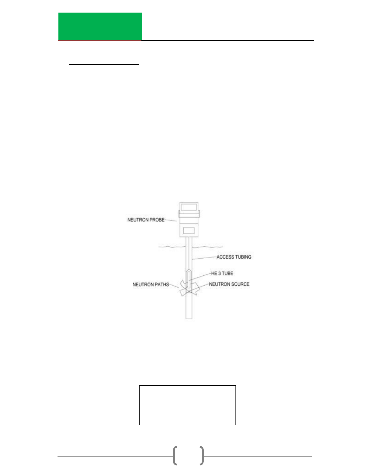
Thank you for your purchase of the InstroTek/CPN Model 503
Elite Hydroprobe. The Model CPN 503 Elite HYDROPROBE,
NEUTRON MOISTURE PROBE, measures the sub-surface moisture
in soil and other materials by use of a probe containing a
source of high-energy neutrons and a slow (thermal) neutron
detector. The probe is lowered into a pre-drilled and cased
hole that’s either 1.5 or 2 inches in diameter.
The source used in this gauge emits fast neutrons. Fast
neutrons from the source interact with Hydrogen in water and
thermalize (slow down) neutrons. The thermal or slow neutrons
are then counted by the He3 tube. Increase in water content
results in a proportional increase in thermal neutron counts
detected by the tube. The moisture data is displayed directly
in units of interest on the electronic assembly which is
connected to the source shield assembly.
This state-of-the-art instrument offers a simple to operate but
superior alternative to other methods of soil moisture
monitoring. The operator needs minimal instructions.
The probe is supplied with an 8 foot cable and ten adjustable
cable stops. Additional stops and longer cable lengths are
available upon request.
Upon retraction of the probe into the shield, the probe latches
automatically in place and must be locked during
transportation.
The complete assembly is supplied with a shipping and
carrying container which contains accessory items, cable,
operating manual, and other materials which the operator
may wish to carry.

InstroTek
3
CPN 503 Elite Features
The CPN 503 Elite Direct Readout Model Provides:
Integral microprocessor for simple function selection.
Rapid, precise repeatable soil moisture measurements.
Light weight and portable.
Field service and component exchange with tools
provided.
Storage and recall selection of linear calibrations for 32
soil or tubing types.
Operator selected time of test, logging format and
units of measurements.
Data transferred serially to a PC via a USB port using a
USB 2.0 A-male to B-male cable.
Data downloaded to a USB mass storage device
(Thumb Drive).
InstroTek
4
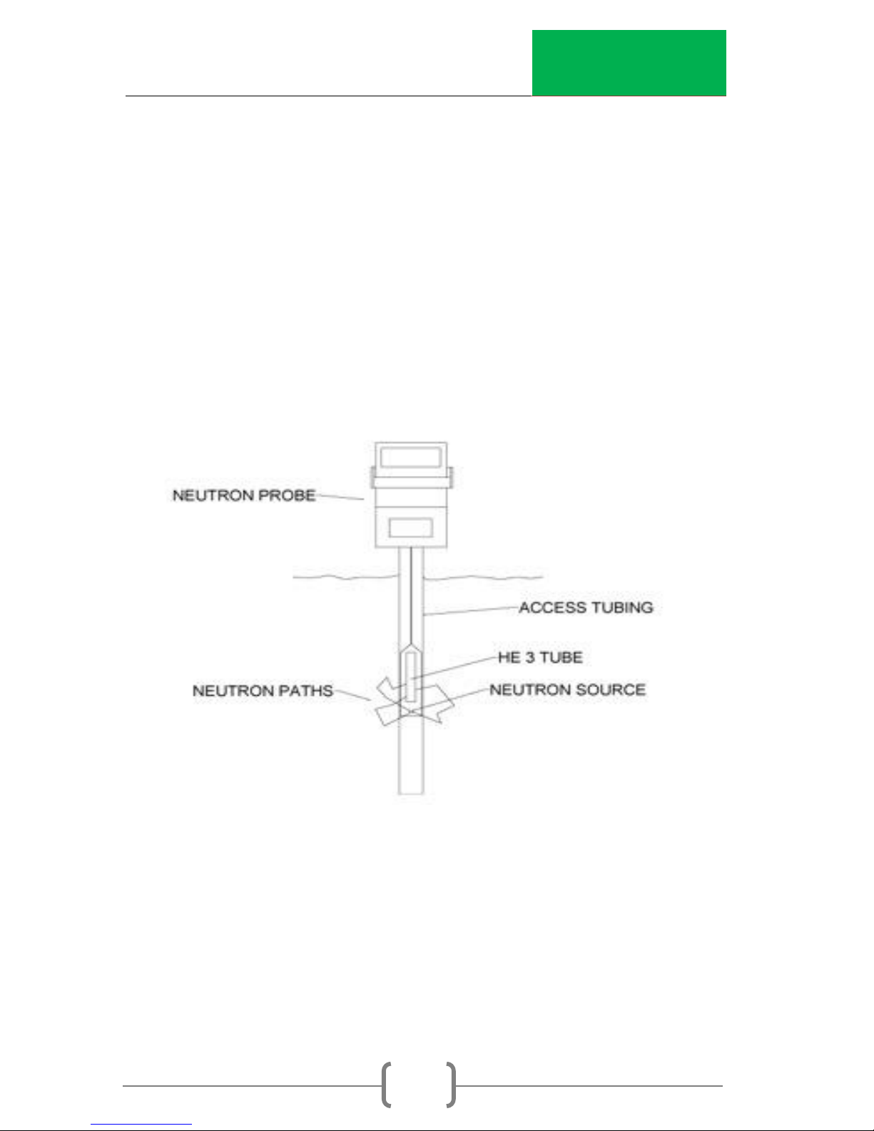
Functional Description
The CPN 503 Elite HYDROPROBE® operates by emitting
radiation from an encapsulated radioactive source,
Americium-241:Beryllium. To determine the moisture content in
the soil, the Americium-241:Beryllium source emits neutron
radiation into the soil under test. The high-energy neutrons are
moderated by colliding with hydrogen in the moisture of the
soil. Only low-energy, moderated neutrons are detected by
the Helium-3 detector. A soil that is wet will give a high count
per time of test. A soil that is dry will give a low count for the
same period of time.
Fig 1.1 Operation of the 503 Elite HYDROPROBE®
InstroTek
5
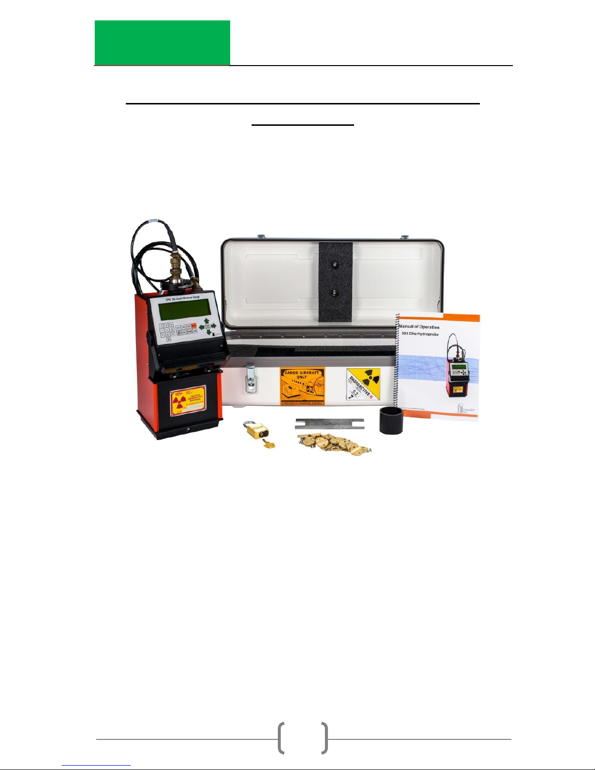
Model 503 Elite Hydroprobe and Standard
Accessories
Each 503 Elite is provided with a durable plastic shipping case
and the items shown listed below. There are no special
instructions for unpacking the 503 Elite Hydroprobe ®. It comes
fully assembled.
1. 503 Elite Hydroprobe®
2. Padlock with Keys – 2 Locks
3. Shipping Case
4. 8 ft. (2.44 meter) Cable
5. 10 Cable Stops
6. Access Collar (1.5”)
7. Operating Manual
8. Spanner Wrench
9. AC Charger
10. Gauge Certificate
11. Leak Test Certificate
7
6
Fig 1.2 Standard Equipment
2 3 4 5 1
8

InstroTek
4
Specifications
Dimensions/Shipping Weights:
Model
Weight
Length
Width
Height
Gauge
Only
15.7lbs
(7.12kg)
7.0”
(178mm)
6.8”
(173mm)
14”
(356mm)
Gauge &
Carry
Case
36.5lbs
(16.6kg)
13.0”
(330mm)
24.0”
(610mm)
10.0”
(254mm)
Probe
Weight
Length
Diameter
Model 1.5
1.7lbs
(0.77kg)
12.7”
(323mm)
1.50”
(38.1mm)
Performance:
Function - Sub-surface moisture measurements
Range - Linear calibration: 0 to 40% per volume, 0.40 g/cc, 25
pcf, 4.8 in/ft
Precision - 0.24% at 24% per volume at one minute
Count Time - User selectable from 1 to 960 seconds
Count Pre scale - 3.75 for 1 min, 15 for 4 min
Display - 4 lines x 20 character Liquid Crystal Display
Data
Storage - 2 GB of storage
Format - Operator programmable
Notes - 0-99 notes of 19 characters each
Counts - 0-99 counts per record

InstroTek
5
Data Output - USB A-B Male Cable download to personal
computer
Calibration - 32 user programmed (linear)
Units - in/ft, pcf, g/cc, %Moist, cm/30cm
Construction
Body - Aluminum with epoxy paint & hard-anodize finish
Wear Parts - Stainless Steel
Electrical:
Power
NiMH 7.5V 2500 mAh Battery Pack
Battery Life - 100 hours of operation
Environmental:
Operating Temperature
Ambient - 32º to 150º F (0º to 66º C)
Storage - -4º to 140º F (-20º to 60º C)
Humidity (Non-Condensing) - 95%
Radiological:
Neutron Source - Maximum 1.85 GBq (50 mCi) Americium-
241:Beryllium
Encapsulation - Double-sealed capsule CPN-131
Shielding - Silicon-Based Paraffin

InstroTek
6
Shipping Requirements:
RQ, UN 3332, RADIOACTIVE MATERIAL, TYPE A PACKAGE,
SPECIAL FORM, 7
Special Form Approval - CZ/1009/S
An NRC or agreement state license is required for domestic use.
Contact CPN - InstroTek for assistance in obtaining training for a
license.
CPN - InstroTek reserves the right to change equipment
specifications and/or design to meet industry requirements or
improve product performance.

InstroTek
7
CPN 503 Elite HYDROPROBE® Inspection
To familiarize yourself with the CPN 503 Elite HYDROPROBE®,
perform the following review.
1. Remove the HYDROPROBE®
from the shipping case and
place it on a solid flat surface,
such as a concrete floor.
2. Examine the keyboard, the
display screen, the cable,
probe, and shield box.
NOTE
The radioactive source is
located at the bottom part of
the probe.
Do not touch this part of the
probe or place yourself in front
of it.
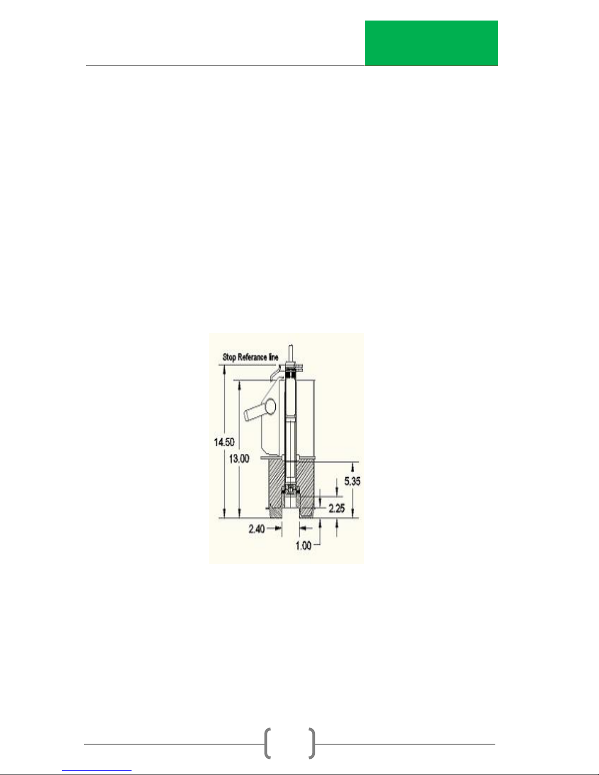
3. Cable Stops
The gauge is supplied with ten each clamp-on cable stops. This
will allow taking measurements at half foot increments in a root
zone up to five feet deep. For a deeper root zone or for smaller
increments, order more stops. Figure 1.4 shows a cross-section
of the gauge. Use it to position the first stop so that the
measurement point on the probe (as indicated by the band) is
in the middle of the top foot of the root zone. Its actual location
will depend upon how high the access tubes stick out of the
soil. Install all tubes to the same height.
Fig 1.3 CPN 503 Elite
HYDROPROBE®
InstroTek
8
For example, if the base of the gauge is 5.0 inches above the
soil, and you want to take the first measurement at 6 inches,
place the stop at 5.35 + 5.0 + 6.0 =16.35 inches above the stop
reference line.
4. Tube Adapter Ring
The bottom of the gauge contains an oversize hole to allow
inserting an adapter ring with a diameter to match the type of
access tubing being used. The ring is secured by a screw
through the front of the casting. Unless specified otherwise at
the time of order, an adapter ring for aluminum tubing will be
supplied. Adapter rings for other types (e.g. diameters) are
available from CPN/InstroTek, Inc. or can be constructed
locally.
Fig 1.4 503 Cross Section
InstroTek
9
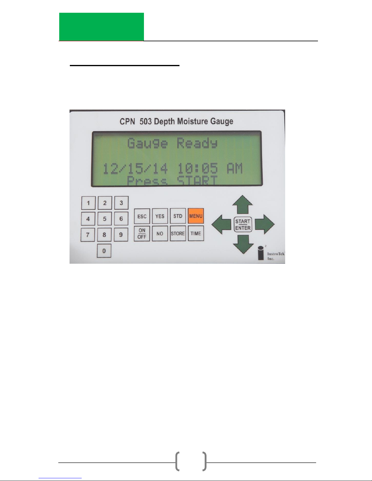
2. Gauge Functions
The CPN 503 Elite includes an updated keypad interface with
menu related function keys.
Function
Start/Enter: Take a reading and select from drop down
menu functions
On/Off: Power on/off function
No: Function key for software/menu requests
Yes: Function key for software/menu requests
Store: Store data and settings to an internal SD card
Time: Enter count time for the length of a reading
Esc: Escape key used to return to main menu or
previous screen
STD: Select Standard Count menu

InstroTek
10
Menu: 14 Item gauge control functions (See Sect. 6 for
details)
Arrow Keys: Navigate through the menus
Numeric Expanded keypad aids in project and data
Keys: entry

InstroTek
11
Standard Count
Taking a Standard Count
Note: A new standard count should be taken at least once a
day.
With the case on the ground, place the gauge on the CPN
nameplate depression on the top of the case. No other
radioactive sources should be within 30 feet of the gauge, and
no source of hydrogen should be within 10 feet after starting
the reading.
To initiate a new standard count, press STD. The display will show
the last standard count and asks you “Would you like to take a
new STD Count?” Select either (Yes/No).
The wax in the shield is not an infinite volume. Thus a standard
count taken in this manner is subject to surrounding conditions.
It is important that the standard count be taken in the same
conditions as that used to establish the calibration, and that the
conditions are the same each time.
See section 11 for further discussion on standard count.
Select TIME
The counting time is selected by pressing the TIME button on the
keypad.
For a given counting rate, the counting time interval determines
the precision of the measurement. The longer the time
selected, the more precise the measurement. Correspondingly,
the longer the counting times the fewer measurements that
can be made in a day. Thus the time interval is normally
selected as the minimum time that will meet your specific
precision.

InstroTek
12
For scheduling-type operation, a count time of 15 seconds will
provide sufficient precision for irrigation scheduling.
See section 11 on Standard Count for a further discussion of
precision.
Select UNITS
Gauge units are under menu item 8.
These are the different units the user can choose:
1. g/cc- grams of water/cubic cm of soil
2. lb/cf – pounds of water/cubic foot of soil
3. in/ft – inches of water/foot of soil
4. cm/30cm – centimeters of water/30 cm of soil
5. %moist – Water content (vol.%) = a* count ratio + b
6. Count – Raw gauge counts/unit time
The choice of display units will depend upon your use.
Researchers will normally prefer grams per cubic centimeter (1)
or percent volume (5), while irrigation schedulers use inches per
foot (3) or centimeter per 30 centimeters (4).
Counts (6) are used for downloading to a software program
and are helpful for troubleshooting. It is the same data, only
differing by the conversion factor.
Once the units have been selected, then each time a Reading
is taken, the display will be in the units selected.
InstroTek
13
Fig 3.1 Operation of the 503 Elite
HYDROPROBE®
3. Operation
Operating Procedures
Taking A Reading (Standard Count Required to Calculate
Moisture)
Before taking a reading, you must select UNITS, TIME and
CALIBRATION, or PROJECT. After this, lower the probe to the
appropriate depth and press START.
Note: The gauge must have a valid standard count to function
correctly.
After the count time, the gauge will display the results.
Project ORCHARD1
MC=1024 R=0.89

InstroTek
14
Test Results
MC Moisture Count: Raw gauge counts/unit time
R Ratio: MC/Standard Count
M Moisture in selected units. (See page 12 for
changing units.)
The moisture is calculated with the following formula:
𝑀 = 𝑅 𝑥 𝐴 + 𝐵
A and B are from the selected calibration that is stored in the
gauge.
32 different calibrations can be stored in the gauge. (See
Section 4, Calibration)
InstroTek
15
4. Calibration
The neutron probe is a source of fast or high energy neutrons
and a detector of slow or thermal neutrons.
The fast neutrons are
slowed down by collision
with the nucleus of matter
in the soil, and then
absorbed by the soil
matter. Since the mass of
the nucleus of hydrogen is
the same as that of a free
neutron, the presence of
hydrogen will result in a
high field of thermal
neutrons. Heavier elements
will also slow down the
neutrons, but not nearly so effectively. While it takes, on the
average, only 18 collisions with hydrogen, it takes 200 with the
next element normally found in agricultural soil.
The thermal neutrons are continually being absorbed by the
matter in the soil. Boron, for example, has a high affinity for
thermal neutrons. The resulting thermal neutron flux will depend
upon a number of factors, both creating and absorbing
thermal neutrons, but most importantly will be how much
hydrogen is present. The neutron probe may thus be used as a
measuring device for moisture in the soil, but it may require
calibration for local soil conditions.
Field Calibration
A field calibration requires the probe, a volume sampler, a
scale and a drying oven. Install the access tube in a
representative point in the soil. Take probe readings in the tube
and volume samples in pairs around the tube. Take them at the
same depth and within a foot or two of the tube.
Seal the volume samples in a sample can or plastic seal bag
immediately after removing from the soil. Be careful not to
InstroTek
16
compact the surrounding soil when taking the samples. Ideally
(20) such measurement pairs should be taken over a range of
moisture conditions.
An alternate method is to use a sampler of smaller diameter
than the tube and take volume samples at each depth while
making the hole to install the access tube. Then take probe
readings at the same depths. This has the advantage that the
calibration is performed on the tube to be used for scheduling.
Another alternate, popular with irrigation schedulers, is to only
take two measurement pairs, one pair at field capacity and a
second at a soil moisture condition near 50% depletion.
Weigh the soil samples wet and dry (24 hrs at 105º C in a vented
oven). Calculate the moisture by weight and the dry soil
density, and then combine to determine the soil moisture
content in inches per foot as follows:
Ww – Wd (gm water) x Wd (gm soil) x 1 (cc water) x12
Inches per foot= Wd(gm soil) V(cc soil) (gm water)
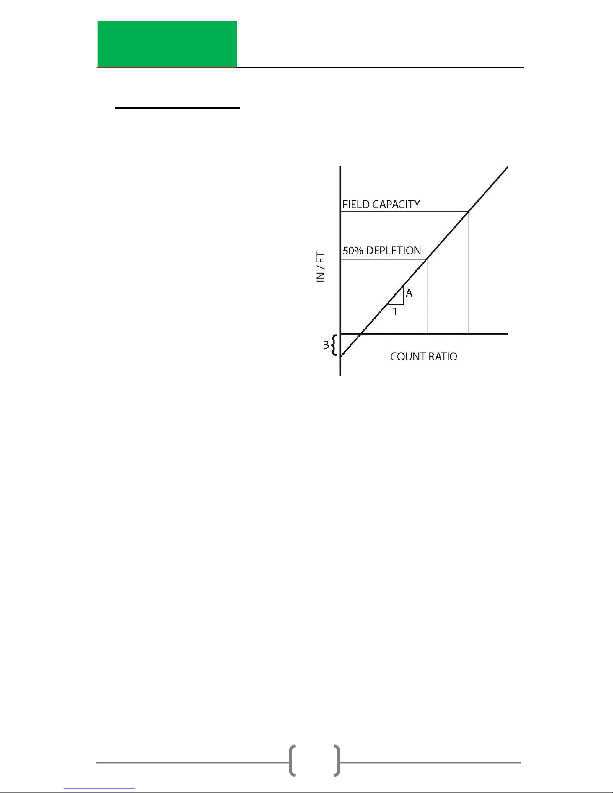
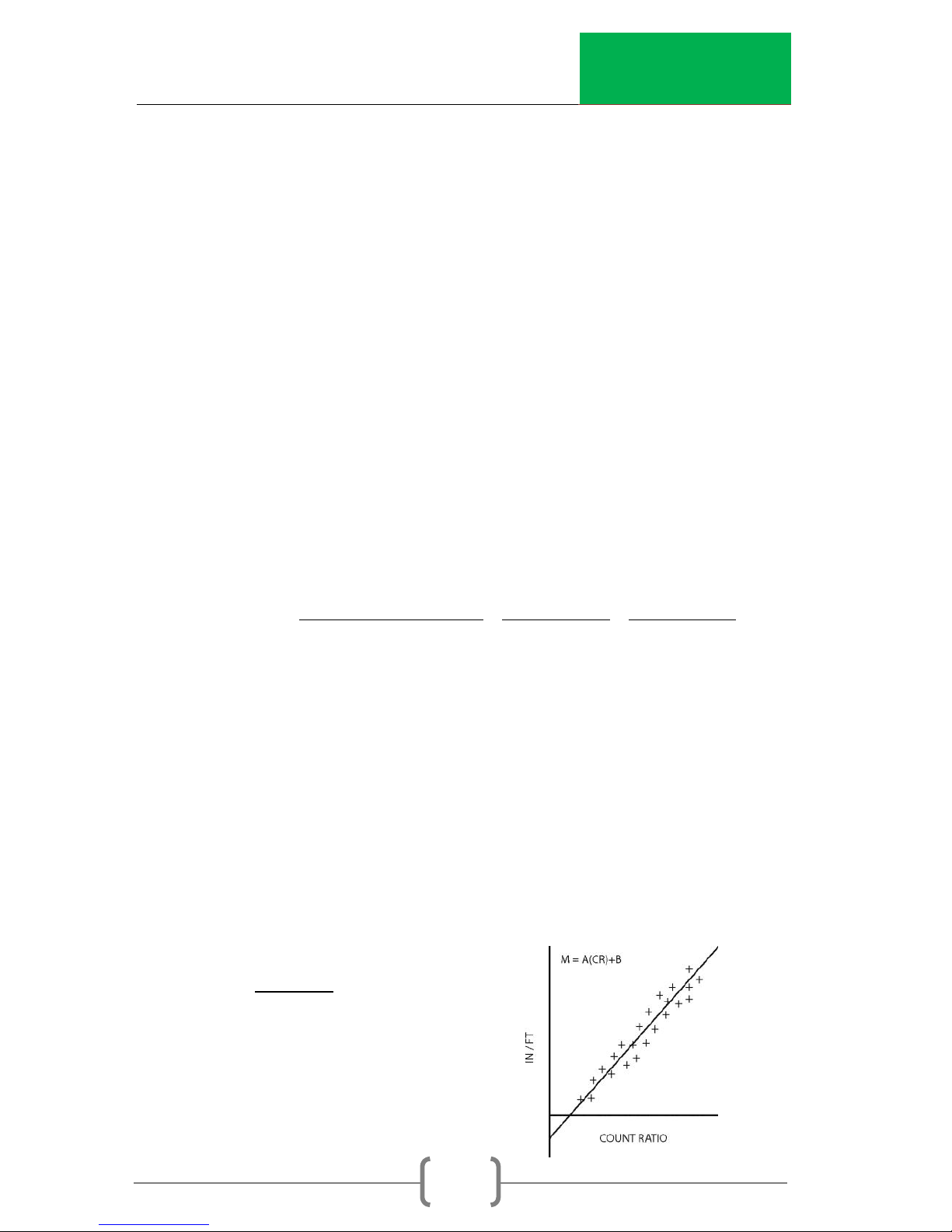
Using linear graph paper, plot the probe readings in count ratio
versus the volume samples in inches per foot.
Calibration
Fit the graph to a straight line. For a scatter diagram of 10 to 20
data pairs, do a linear regression on a hand calculator. For only
two pairs, use the following equations to determine the slope
and intercept.
MH - ML
Slope: A = RH – RL
Intercept: B = ML – A x RL
Then: M = (A x r) + B
InstroTek
17
Where:
m = moisture in inches per foot
MH = high moisture value in inches per foot
Example:
A field capacity of 3.8 in/ft gives a ratio of 1.500, while 50
percent depletion gives a ratio of 0.77.
3.8 - 1.90
A = 1.5 - 0.77 = 2.603 in / ft / count ratio
B = 1.9 - 2.603 x 0.77 = -0.1043 or
M = 2.603 x r - 0.1043
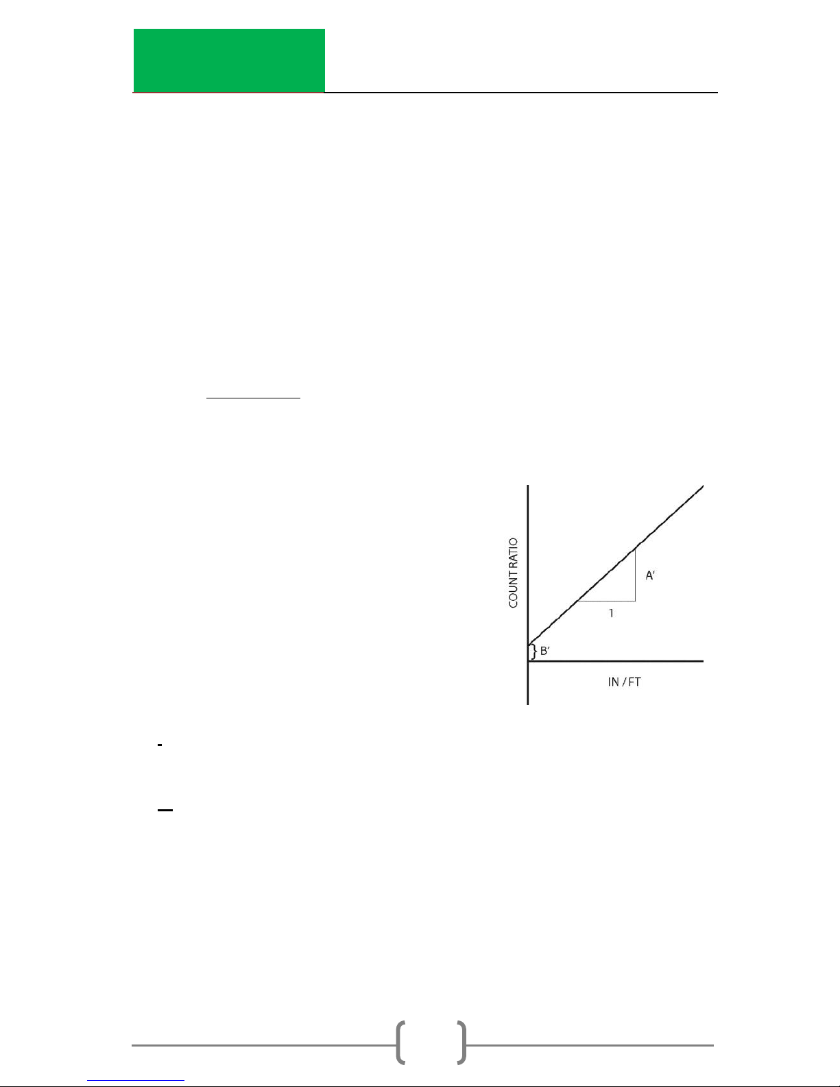
The 503 Elite defines the slope and
intercept with water on the vertical
axis and ratio on the horizontal axis.
If your data has been plotted with
the axis reversed as shown in the
following Figure, it will be necessary
to transpose the slope and
intercept terms before entering in
the DR.
l
A=A’
B’
B=A’
Laboratory Calibration
For a laboratory calibration, two known calibration points are
needed. A high calibration standard can be a barrel of sand
saturated with water (typically 0.32 gm/cc. i.e. 0.32 grams of
InstroTek
18
water per cubic centimeter of soil, or 32% water by volume, or
3.84 inches of water per foot of soil). A low standard of dry sand
would be 0.0 gm/cc. This is how the factory calibration is
determined. It will be applicable for sandy soils with no
significant organics.
Range
The linear calibration supplied with the 503 Elite is useful over the
most commonly used moisture range, 0 to 40%. For use in
moisture contents higher than this, it is necessary to have a
special calibration that covers the intended range of use.
Entering Calibrations
Calibrations can be entered manually or by self-calibration.
Changing Existing Calibration:
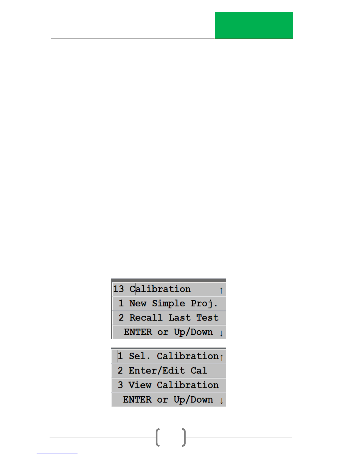
Press MENU – Use Arrow keys to select ’13. Calibration’
Press ENTER.
Use Arrow keys to select ‘2. Enter/Edit Cal’. Press Enter.
InstroTek
19
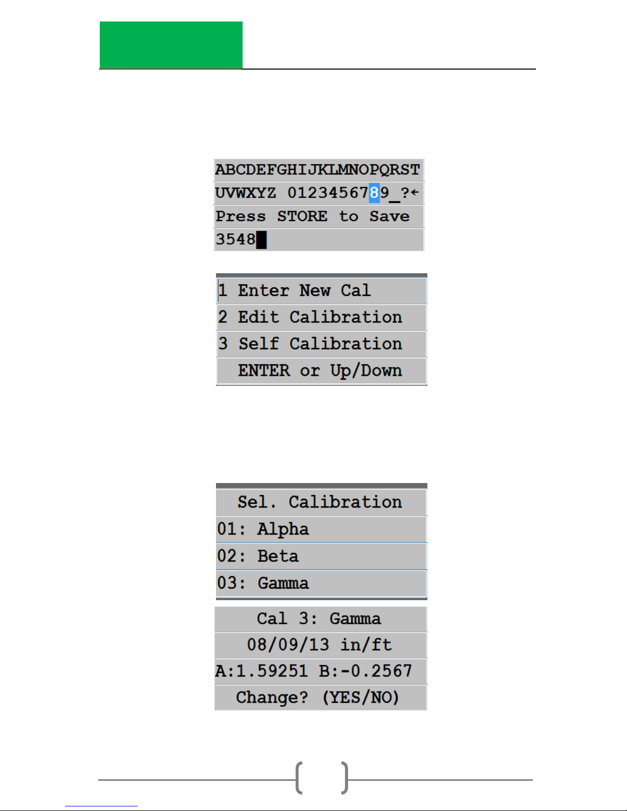
You will be prompted to enter the Password (3548). Enter it
and press STORE.
Use the Arrow keys to select ‘1. Enter New Cal’. Press ENTER.
Use the Arrow keys to select the calibration you wish to
change. You will be asked if you really wish to change the
calibration.
Press YES.
 Loading...