

CPI Communications TTP216 User Manual

Instruction Manual
TTP216 Series
Multi-Frequency
Tone Termination Panel
1/2013
CPI Communications 941 Hensley Lane Wylie, Texas 75098
Phone (972)429-7160 (800)869-9128 Fax (972)429-7165 (888) 437-5360 www.cpicomm.com

TTP216 Specifications
Specifications: Subject to change without notice
Size: 5.5" wide
1.5" high
7.5" length
Weight: 1.6 lbs.
Connections: modular and screw terminals to phone line (remote)
modular and screw terminal to radio
modular desk microphone connection
Input voltage: +12 to +13.8 VDC @150mA (18 mA idle)
Line impendence: 600 ohms
Line output to phone line +10 dBm max. preset to 0 dBm
Line output from phone line -40 dBm to +10 dBm (function tone referenced)
RX input from radio: 70 mVrms or greater
Notch filter: 2175 down 50 dB from 1000 Hz reference
Control tones: Guard tone = 2175 Hz for 40 mS
Function tones
F1 = 1950 Hz for 40 mS
F2 = 1850 Hz for 40 mS
F3 = 1750 Hz for 40 mS
F4 = 1650 Hz for 40 mS
F5 = 1550 Hz for 40 mS
F6 = 1450 Hz for 40 mS
F7 = 1350 Hz for 40 mS
F8 = 1250 Hz for 40 mS
F9 = 1150 Hz for 40 mS
F10 = 1050 Hz for 40 mS
F11 = 950 Hz for 40 mS
F12 = 850 Hz for 40 mS
F13 = 750 Hz for 40 mS
F14 = 650 Hz for 40 mS
F15 = 550 Hz for 40 mS
F16 = 450 Hz for 40 mS
Monitor = 2050 Hz for 40 mS
Hold Tone = 2175 Hz for duration of PTT
Control function outputs: PTT and Monitor selection are
form "C" relay contacts. 1 amp @ 30 VDC
F1/F2 are form "C" relay contact or open collector
F3-F16 are open collector
I. Connectors
connector location function
J1
J2
J3
J4
J5
J6, J7
II. Connector Pinouts
front panel connects to local mic when modular interconnection configuration is used
front panel connects to radio when modular interconnection configuration is used
back panel connects to remotes
board, rear
board, rear auxiliary 4-wire TX connection to remotes
board, front
auxiliary 2-wire or 4-wire RX connection to remotes
auxiliary 12 Volt D.C. supply connection
connects to radio and local mic when hand-wired interconnection configuration is
used
pin function
J1-1
J1-2
J1-3
J1-4
J1-5
J1-6
J1-7
J1-8
pin function
J3-1
J3-2
J3-3
J3-4
J3-5
J3-6
n.c.
n.c.
Local Mic PTT output
Local Mic Audio output
ground
Local Mic Monitor output
n.c.
n.c.
n.c.
4-Wire TX
2-Wire; 4-Wire RX
2-Wire; 4-Wire RX
4-Wire TX
n.c.
pin function
J2-1
J2-2
J2-3
J2-4
J2-5
J2-6
J2-7
J2-8
pin function
J4-1
J4-2
J4-3
J4-4
pin function
J5-1
J5-2
J5-3
Radio RX Audio output
n.c.
Radio PTT input
Radio TX Modulation input
ground
Radio Monitor input
Radio F1/F2 input
n.c.
power supply ground
+12 Volts D.C. input
2-Wire; 4-Wire RX
2-Wire; 4-Wire RX
4-Wire TX
n.c.
4-Wire TX
pin function
J6-1
J6-2
J6-3
J6-4
J6-5
J6-6
J6-7
J6-8
J6-9
J6-10
+12 Volts D.C. input
power supply ground
PTT output
RX Audio input
Monitor relay output common
Monitor relay output normally open
Monitor relay output normally closed
TX Modulation output
Local Mic Audio input
Squelch Control input
pin function
J7-1
J7-2
J7-3
J7-4
J7-5
J7-6
J7-7
J7-8
J7-9
J7-10
+12 Volts D.C. input
power supply ground
F1/F2 relay output common
F1/F2 relay output normally open
F1/F2 relay output normally closed
F1 open-collector output
F2 open-collector output
F3 open-collector output
F4 open-collector output
F5 open-collector output
III. Front Panel Indicators
indicator color function
PTT
MON
F1
F2
F3
F4
F5
red PTT on
green Monitor on
yellow F1/BCD0 output on (open collector low)
yellow F2/BCD1 output on (open collector low)
yellow F3/BCD2 output on (open collector low)
yellow F4/BCD3 output on (open collector low)
yellow F5/BCD4 output on (open collector low)
IV. Front Panel Adjustments
adjustment trimpot location function
RX AUD
TX MOD
MIC AUD
LINE AUD
BALANCE
R105 front panel adjusts radio RX audio output level to remotes
R106 front panel
adjusts remote audio level to radio TX modulation
input *
R107 front panel adjusts local mic level to remotes
R108 front panel
adjusts remote line audio level for all termination
panel functions *
R104 circuit board sets hybrid balance of remote line
* adjustment is affected by JP2 setting
V. Option Settings
Options are selected by setting jumpers. Pin 1 of each jumper group is toward the left side or the back of the board, depending upon its orientation
in the layout. The following descriptions show the position of each jumper on the board when the board is positioned with the front to the bottom
of the illustration.
JP1 2-Wire / 4-Wire Select
Selects remote line interface
1-2 (default) selects 2-wire interface
2-3 selects 4-wire interface
JP2 Line Audio Gain Mode
Selects Manual or Automatic Line Audio Gain
1-2 (default) selects automatic gain control
2-3 selects manual gain control -- use Line Aud (R108) to adjust.
JP3 Mod Out Source Impedance
Selects low or high Mod Out impedance
1-2 (default) selects low impedance (nominal 600 Ohms)
2-3 selects high impedance (47K Ohms)
JP4 Local Mic Audio Gain
Selects gain of the Local Mic amplifier
1-2 (default) selects low gain
2-3 selects high gain
JP5 Squelch Control Mode
Selects Squelch Control input logic level
1-2 (default) mute RX Audio when input low
2-3 mute RX Audio when input high
JP6 RX Audio Gain
Selects gain of the RX Audio amplifier
1-2 (default) selects low gain
2-3 selects high gain
JP7 PTT Keying
Selects PTT Keying output
1-2 (default) key = ground; unkey = open
2-3 key = +12 Volts; unkey = open
JP8 Local Mic Audio Control
Selects Local Mic Muting logic during remote PTT -should be set the same as JP7
1-2 (default) key to ground
2-3 key to + voltage (≥ 5 Volts D.C.)
JP9 F1 / F2 Ground
Selects internal ground on F1 / F2 output
JP11 Monitor With PTT
Selects automatic Monitor with all remote PTT's
1-2 (default) automatic monitor disabled
2-3 automatic monitor enabled
JP12 Monitor Mode
Selects duration of monitor output
1-2 (default) latched -- on with Monitor command; off with PTT
2-3 momentary on with Monitor command
JP13 Monitor Ground
Selects internal ground on Monitor output
1-2 (default) internal ground disabled
2-3 internal ground enabled
JP14 Local Mic Termination
Selects Local Mic biasing and input resistance
1-3 (default) no termination
1-2 +12 Volt bias; R86 sets input resistance
3-4 input to ground; R86 sets resistance
1-2 (default) internal ground disabled
2-3 internal ground enabled
JP10 F1 / F2 Relay
Selects F1 / F2 output relay
1-2 (default) relay enabled -- use F1/F2 outputs at J2, J7
2-3 relay disabled -- use F1/BCD0 output at J7
VI. J1 and J2 Configuration Settings
Jumper groups E1-x and E2-x directly enable configuration of the J1 and J2 connectors. Alternatively, connectors E1 and E2 can be manually
wired in any configuration.
jumper jack signal
E1-1
E1-2
E1-3
E1-4
E1-5
E1-6
E1-7
E1-8
E2-1
E2-2
E2-3
E2-4
E2-5
E2-6
E2-7
E2-8
J1 - Local Mic
J1 - Local Mic
J1 - Local Mic PTT
J1 - Local Mic Mic Audio
J1 - Local Mic Ground
J1 - Local Mic Monitor
J1 - Local Mic
J1 - Local Mic
J2 - Radio RX Audio
J2 - Radio
J2 - Radio PTT
J2 - Radio TX Mod
J2 - Radio Ground
J2 - Radio Monitor
J2 - Radio F1/F2
J2 - Radio
VII. Programming
A. Hardware
The programming hardware is located on the right-hand side of the circuit board, and consists of Tone Select pushbutton S1, eight-position DIP
switch S2 and a row of twenty LED's, identified with the numbers 450 through 1950 (EIA Tone LED’s) and the letters A through D (ABCD
LED’s). Functions of the individual S2 DIP switch sections are as follows:
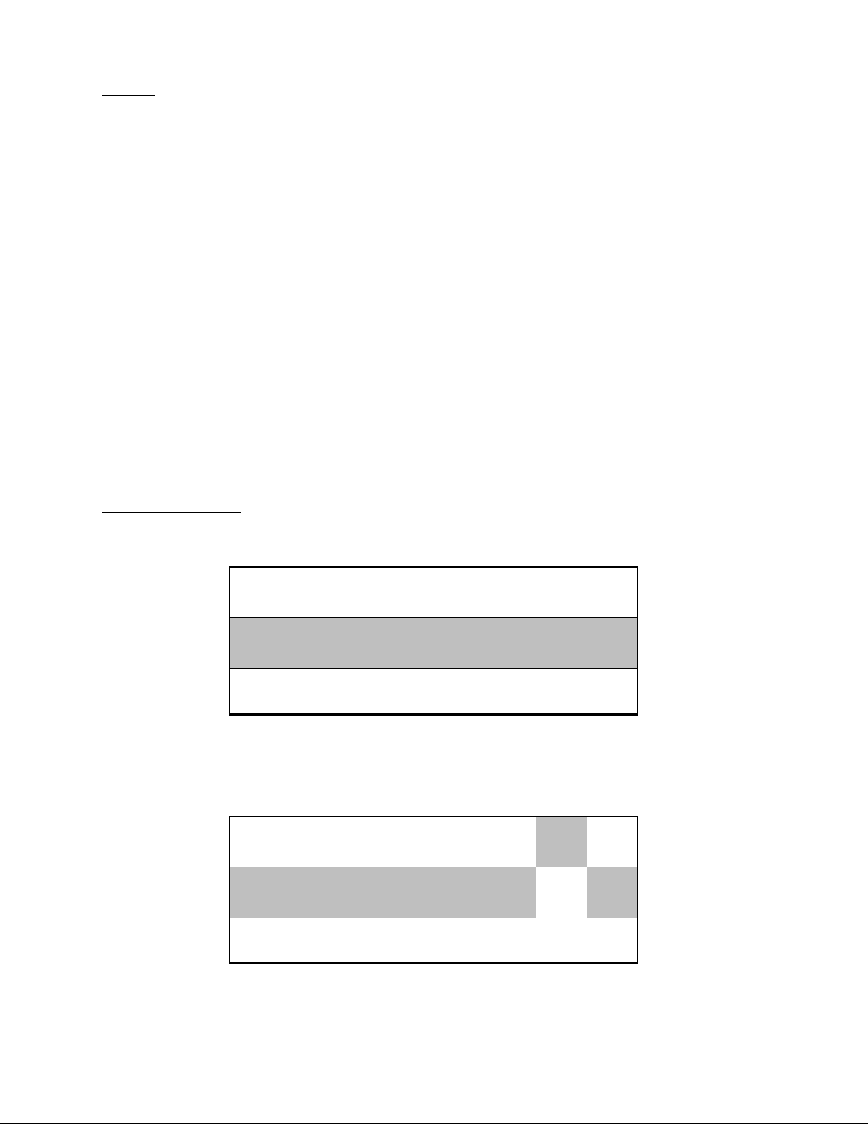
OFF OFF OFF OFF OFF OFF OFF OFF
ON ON ON ON ON ON ON ON
8 7 6 5 4 3 2 1
Y X F5 F4 F3 F2 F1 PROG
switch function
S2-1
S2-2
S2-3
S2-4
S2-5
S2-6
S2-7
S2-8
Program Mode Enable
F1 select
F2 select
F3 select
F4 select
F5 select
X
Y
B. Options
The TTP200 is programmed by selecting a pre-programmed "EIA Tone-to-Output" assignment pattern, or "Pre-Set." Pre-Sets are available for
several different output options:
1. Discrete 1 of 5 Outputs
Pre-Sets 1 through x assign the 16 standard EIA tones to activate one, and only one, of the "Fx" outputs at a time.
2. Discrete "Split" Outputs
Pre-Sets x though y split the five "Fx" outputs into two groups, one containing “ 1 of 3” outputs F1 through F3 and the other containing “1 of 2”
outputs F4 and F5.
3. Discrete "Wildcard" Outputs
Pre-Sets x though y establish outputs F1 through F4 as discrete outputs and use F5 as a "wild card" output that toggles independently of the other
outputs.
4. BCD Output
Pre-Sets x through y produce a BCD output based on the 16 EIA tones.
5. Customized Output
Once a Pre-Set has been loaded, it can be customized by manually re-programming some or all of the individual EIA Tone-to-Output
assignments. Blank Pre-Sets are provided for each of the four output types (three discrete and one binary) to facilitate building up custom EIA
Tone-to-Output assignments "from scratch."
6. Inverted Output
Leaving S2-2 (F1) ON during normal operation inverts the "Fx" outputs.
C. Settings and Procedures
1. S2 Setting -- Normal Operation:
OFF OFF OFF OFF OFF OFF OFF OFF
8 7 6 5 4 3 2 1
Y X F5 F4 F3 F2 F1 PROG
2. S2 Setting -- Inverted Outputs:
OFF OFF OFF OFF OFF OFF OFF
ON
8 7 6 5 4 3 2 1
Y X F5 F4 F3 F2 F1 PROG

3. To Check the Existing Program:
OFF OFF OFF OFF OFF OFF OFF
8 7 6 5 4 3 2 1
Y X F5 F4 F3 F2 F1 PROG
a. Turn the PROG switch ON.
b. During the first three seconds, the ABCD LED’s indicate the number of the currently loaded Pre-Set in binary form. This indication
flashes if the PRE-Set has been customized.
c. After the ABCD LED’s go out, switches F1 through F5 can be used to select a specific output to be checked.
d. The front panel LED's and the EIA Tone LED's indicate individual EIA Tone-to-Output assignment of the selected Output.
e. Normal operation resumes when all switches are returned to the OFF position. The existing settings are not modified.
4. To Load a Pre-Set:
OFF OFF OFF OFF OFF OFF
ON ON ON ON ON ON
ON ON
8 7 6 5 4 3 2 1
Y X F5 F4 F3 F2 F1 PROG
a. Turn the X switch ON.
b. Turn the PROG switch ON.
c. The ABCD LED's indicate Pre-Set number in binary form, starting with 0001.
d. Use the Tone Select pushbutton to step through the Pre-Sets. Press and release the Tone Select pushbutton to advance to the next
Pre-Set. Stop when the number of the desired Pre-Set is indicated in binary form on the ABCD LED’s.
e. To complete loading of the Pre-Set:
i. Turn the X switch OFF.*
ii. Turn the PROG switch OFF.*
The TTP200 will then return to normal operation.
*Turning the PROG switch OFF before turning the X switch OFF exits the Load function without saving the new Pre-Set.
Example: Loading Pre-Set #3
a. Turn the X switch ON.
b. Turn the PROG switch ON.
c. Press and release the Tone Select pushbutton until the ABCD LED’s indicate the number “3” in binary form, that is,
LED A = ON
LED B = ON
LED C = OFF
LED D = OFF.
d. Turn the X switch OFF.
e. Turn the PROG switch OFF.
f. The TTP200 is now ready for use.
 Loading...