

CPI VZC-6967AG, VZC-6967AT, VZC-6967AB, VZC-6967AH, VZC-6967AJ Installation, Operation And Preventive Maintenance Manual
...Page 1

INSTALLATION, OPERATION, AND
PREVENTATIVE MAINTENANCE
MANUAL
CHPA (COMPACT HIGH POWER AMPLIFIER)
For Use With Model Numbers...
Service Center Headquarters and Design Center
West Coast Operations
811 Hansen Way
Palo Alto, CA 94303
Manufacturing
East Coast Operations
45 River Drive
Georgetown, ON
Canada L7G 2J4
VZC – 6967AT
VZC – 6967AN
VZC – 6967AM
VZC – 6967AD
VZC – 6967AB
VZC – 6967AG
VZC – 6967AJ
VZC – 6967AH
VZU – 6997AC
VZU – 6997AB
VZU – 6996AB
VZU – 6996AC
VZU – 6997AE
VZU – 6997AG
VZU – 6995AY
VZU – 6997AA
VZU – 6997AD
VZU – 6997AJ
VZU – 6996AY
VZU – 6997CY
VZU – 6997AX
VZU – 6997AY
DOC.01023245 REV.K
THIS DOCUMENT IS THE PROPERTY OF COMMUNICATIONS & POWER INDUSTRIES.
REPRODUCTION OR RELEASE WITHOUT EXPRESS PERMISSION IS STRICTLY PROHIBITED
Page 2

CHPA SERIES
PROPRIETARY INFORMATION
The design and other information contained in this document are provided solely for the
installation, operation, and maintenance of CPI equipment. Except for rights expressly granted
by contract, all such information is the exclusive property of CPI, Satcom Division. This
document may not be duplicated, in whole or in part, or be used for manufacture without
written permission of CPI, Satcom Division.
Copyright © 2009 by Communications & Power Industries, Inc. All rights reserved.
ii
THIS DOCUMENT IS THE PROPERTY OF COMMUNICATIONS & POWER INDUSTRIES.
REPRODUCTION OR RELEASE WITHOUT EXPRESS PERMISSION IS STRICTLY PROHIBITED
DOC.01023245 REV.K
Page 3

CHPA SERIES
Table of Contents
SAFETY................................................................................................................................................... S-1
INTRODUCTION................................................................................................................................... S-1
HIGH VOLTAGE EQUIPMENT......................................................................................................... S-1
PERSONNEL OPERATING GUIDELINES ....................................................................................... S-1
WHEN IS VOLTAGE "HIGH"?.......................................................................................................... S-1
GENERAL GUIDELINES................................................................................................................... S-2
MICROWAVE RADIATION................................................................................................................ S-4
PERSONNEL OPERATING GUIDELINES ....................................................................................... S-4
MICROWAVE DISCUSSION............................................................................................................. S-5
GENERAL MICROWAVE GUIDELINES......................................................................................... S-5
PHYSICAL SAFETY........................................................................................................................... S-6
LIFTING HEAVY OBJECTS..............................................................................................................S-6
EXTENDING RACK SLIDES.............................................................................................................S-6
CHAPTER 1 INTRODUCTION............................................................................................................1-1
1.1 OVERVIEW................................................................................................................................. 1-1
1.2 ABOUT THIS MANUAL............................................................................................................1-3
1.3 MAJOR SUBSYSTEMS AND THEIR FUNCTIONS..............................................................1-4
1.4 TECHNICAL DESCRIPTION...................................................................................................1-4
1.4.1 RF SUBSYSTEM..................................................................................................................1-4
1.4.2 POWER SUPPLY SUBSYSTEM .........................................................................................1-6
1.4.3 POWER FACTOR CORRECTION MODULE ....................................................................1-7
1.4.4 POWER PROCESSOR MODULE........................................................................................1-7
1.4.5 HIGH-VOLTAGE MODULE ...............................................................................................1-7
1.4.6 RF POWER MONITOR MODULE......................................................................................1-7
1.4.7 CONTROL AND DISPLAY MODULES.............................................................................1-8
1.5 LRU PHILOSOPHY ...................................................................................................................1-8
1.6 OPTIONAL FEATURES............................................................................................................1-9
CHAPTER 2 UNPACKING AND INSTALLATION..........................................................................2-1
OC.01023245 REV.K
D
THIS DOCUMENT IS THE PROPERTY OF COMMUNICATIONS & POWER INDUSTRIES.
REPRODUCTION OR RELEASE WITHOUT EXPRESS PERMISSION IS STRICTLY PROHIBITED
iii
Page 4

CHPA SERIES
2.1 OVERVIEW................................................................................................................................. 2-1
2.2 PRE-INSPECTION .....................................................................................................................2-1
2.3 UNPACKING...............................................................................................................................2-1
2.4 PREPARING FOR INSTALLATION....................................................................................... 2-2
2.5 INSTALLATION.........................................................................................................................2-2
2.5.1 MECHANICAL INSTALLATION.......................................................................................2-2
2.5.2 ELECTRICAL CONNECTIONS..........................................................................................2-3
2.5.3 PRIME POWER ....................................................................................................................2-3
2.5.4 GROUNDING .......................................................................................................................2-4
2.5.5 I/O INTERFACES.................................................................................................................2-4
2.5.6 RF CONNECTIONS .............................................................................................................2-4
2.5.7 RF OUTPUT (WAVEGUIDE CONNECTION)(J3).............................................................2-5
2.5.8 COOLING CONSIDERATIONS..........................................................................................2-5
CHAPTER 3 INTERFACES ..................................................................................................................3-1
3.1 OVERVIEW................................................................................................................................. 3-1
3.2 CHPA CONTROL MODE HIERARCHY................................................................................3-1
3.3 SERIAL REMOTE INTERFACE ............................................................................................. 3-2
3.4 RF SWITCH SYSTEM INTERFACE.......................................................................................3-4
3.4.1 RELAY DEFINITIONS ........................................................................................................3-4
3.5 EXTERNAL INTERLOCKS INTERFACE .............................................................................3-6
3.6 COMPUTER INTERFACE........................................................................................................3-8
3.6.1 CIF HARDWARE CONFIGURATION ...............................................................................3-8
3.7 COMPUTER INTERFACE (CIF) PROTOCOL .....................................................................3-9
3.8 PROTOCOL MESSAGE STRUCTURE...................................................................................3-9
3.9 COMMAND AND RESPONSE FORMAT.............................................................................3-10
3.9.1 HEADER AND ENDING BYTES...................................................................................... 3-10
3.9.2 ADDRESS BYTE................................................................................................................3-11
3.9.3 COMMAND BYTE.............................................................................................................3-11
3.9.4 RESPONSE BYTE(S) .........................................................................................................3-11
iv
THIS DOCUMENT IS THE PROPERTY OF COMMUNICATIONS & POWER INDUSTRIES.
REPRODUCTION OR RELEASE WITHOUT EXPRESS PERMISSION IS STRICTLY PROHIBITED
DOC.01023245 REV.K
Page 5

CHPA SERIES
3.9.5 REJECT BYTE(S)...............................................................................................................3-11
3.9.6 CHECK BYTE.....................................................................................................................3-12
3.9.7 CARRIAGE RETURNS AND LINE FEEDS.....................................................................3-13
3.10 COMMANDS .............................................................................................................................3-13
3.10.1 SLOW COMMANDS..........................................................................................................3-16
3.11 STATUS BYTE DEFINITIONS...............................................................................................3-17
3.12 ID/VERSION MESSAGE .........................................................................................................3-21
CHAPTER 4 INITIAL POWER ON AND CHECKOUT ...................................................................4-1
4.1 OVERVIEW................................................................................................................................. 4-1
4.2 PRE-POWER PROCEDURES...................................................................................................4-1
4.3 USING THE FRONT PANEL....................................................................................................4-2
4.4 INITIAL POWER-ON PROCEDURES....................................................................................4-3
4.4.1 POWER-ON SELF-TEST AND HEATER TIME DELAY..................................................4-3
4.5 VERIFYING OPERATIONAL SETTINGS.............................................................................4-4
4.6 SETTING THE FAULT AND ALARM TRIP POINTS..........................................................4-4
4.7 SETTING SERIAL REMOTE AND CIF PORT PARAMETERS.........................................4-6
4.8 VERIFYING RF OUTPUT LEVEL ..........................................................................................4-7
4.9 VERIFYING RF ALARM AND RF FAULT TRIP POINTS..................................................4-8
4.10 TESTING THE CHPA VIA COMPUTER CONTROL ..........................................................4-9
4.11 TESTING OPTIONAL EQUIPMENT......................................................................................4-9
4.11.1 REMOTE CONTROL INTERFACE ....................................................................................4-9
CHAPTER 5 OPERATION....................................................................................................................5-1
5.1 OVERVIEW................................................................................................................................. 5-1
5.2 ESSENTIAL CHPA OPERATING PROCEDURES...............................................................5-2
5.2.1 TRANSMIT...........................................................................................................................5-2
5.3 NORMAL SHUTOFF .................................................................................................................5-3
5.4 BASIC CHPA OPERATION......................................................................................................5-3
OC.01023245 REV.K
D
THIS DOCUMENT IS THE PROPERTY OF COMMUNICATIONS & POWER INDUSTRIES.
REPRODUCTION OR RELEASE WITHOUT EXPRESS PERMISSION IS STRICTLY PROHIBITED
v
Page 6

CHPA SERIES
5.5 CHPA STATES AND DESCRIPTION......................................................................................5-4
5.6 INITIALIZATION AND POWER-ON SELF-TEST (POST) STATE...................................5-4
5.7 HEATER TIME DELAY (HTD) STATE..................................................................................5-5
5.8 STANDBY STATE ......................................................................................................................5-6
5.9 TRANSMIT STATE....................................................................................................................5-7
5.10 FAULT STATE............................................................................................................................5-7
5.11 CHPA CONTROL MODES AND HIERARCHY....................................................................5-8
5.12 RF CONTROL MODES .............................................................................................................5-9
5.13 SPECIAL CHPA FUNCTIONS ...............................................................................................5-10
5.13.1 FACTORY AUTHORIZED ACCESS MODE ...................................................................5-10
5.14 TERMINOLOGY ...................................................................................................................... 5-10
5.15 EXITING A MENU...................................................................................................................5-11
5.16 DATA ENTRY RULES.............................................................................................................5-11
5.17 QUICK ACCESS CODES.........................................................................................................5-13
CHAPTER 6 MAINTENANCE .............................................................................................................6-1
6.1 OVERVIEW................................................................................................................................. 6-1
6.2 SCHEDULED PREVENTIVE MAINTENANCE....................................................................6-1
6.3 MECHANICAL PREVENTIVE MAINTENANCE.................................................................6-2
6.4 VISUAL INSPECTION...............................................................................................................6-4
6.4.1 INSPECTING AND CLEANING AIR FILTERS.................................................................6-5
6.4.2 CHECKING A3 LEDS AND DISPLAY...............................................................................6-5
6.4.3 COLLECTOR AIR SYSTEM MAINTENANCE .................................................................6-5
6.4.4 CHECKING B1 COLLECTOR BLOWER...........................................................................6-6
6.4.5 MISCELLANEOUS CLEANING.........................................................................................6-6
6.5 ELECTRICAL PREVENTIVE MAINTENANCE ..................................................................6-6
6.6 SPARE TWT MAINTENANCE AND PERIODIC OPERATION OF THE AMPLIFIER. 6-6
6.7 PERFORMANCE TESTING .....................................................................................................6-8
vi
THIS DOCUMENT IS THE PROPERTY OF COMMUNICATIONS & POWER INDUSTRIES.
REPRODUCTION OR RELEASE WITHOUT EXPRESS PERMISSION IS STRICTLY PROHIBITED
DOC.01023245 REV.K
Page 7

CHPA SERIES
6.8 POWER AND GAIN ...................................................................................................................6-8
CHAPTER 7 DRAWINGS AND SCHEMATICS................................................................................7-1
CHAPTER 8 SUPPLEMENTARY DATA............................................................................................8-1
APPENDIX A SPECIFICATIONS.......................................................................................................A-1
APPENDIX B CONTROL APPEARANCE AND CONTENT ..........................................................B-1
B.1 OVERVIEW................................................................................................................................B-1
B.2 BUTTONS ...................................................................................................................................B-1
B.3 LEDS............................................................................................................................................B-2
B.4 BEEPER.......................................................................................................................................B-3
B.5 ALPHANUMERIC DISPLAY DEFINITION .........................................................................B-3
B.6 METERS......................................................................................................................................B-5
B.6.1 HVPS METER DISPLAY LIST: .........................................................................................B-5
B.6.2 RF METERS.........................................................................................................................B-5
B.6.3 METER ORDER ..................................................................................................................B-5
B.6.4 METER LIST........................................................................................................................B-6
B.7 FAULT MESSAGES THAT CORRESPOND TO DIGITAL STATUS LINES...................B-6
B.8 FAULT MESSAGES GENERATED BY LIMIT COMPARISONS .....................................B-7
B.9 ALARMS.....................................................................................................................................B-8
B.10 CONTROL MENU.................................................................................................................B-9
B.11 DATA ENTRY RULES..........................................................................................................B-9
B.11.1 CATEGORIES....................................................................................................................B-13
B.11.2 RF CONTROL....................................................................................................................B-13
B.11.3 LINEARIZER CONTROL (OPTIONAL)..........................................................................B-14
B.12 LINEARIZER ADJUSTMENT...........................................................................................B-15
B.13 RF TRIP LIMITS/SWITCH PORT RELAY SETTINGS................................................B-16
B.13.1 FAULT LOG ......................................................................................................................B-17
B.13.2 FACTORY AUTHORIZED ACCESS CODE (FAAC).....................................................B-18
B.13.3 FAULT TRIP SETTING ....................................................................................................B-19
OC.01023245 REV.K
D
THIS DOCUMENT IS THE PROPERTY OF COMMUNICATIONS & POWER INDUSTRIES.
REPRODUCTION OR RELEASE WITHOUT EXPRESS PERMISSION IS STRICTLY PROHIBITED
vii
Page 8

CHPA SERIES
B.13.4 FACTORY TESTS.............................................................................................................B-19
B.13.5 RESET ELAPSED TIME METERS ..................................................................................B-19
B.13.6 RESET TO FACTORY DEFAULTS.................................................................................B-20
B.13.7 CHPA HVPS TEST MODE ...............................................................................................B-20
B.13.8 USER TESTS......................................................................................................................B-21
B.13.9 TIME/DATE SET...............................................................................................................B-22
B.13.10 REMOTE/COMPUTER INTERFACE PARAMETERS...............................................B-23
B.13.11 SOFTWARE VERSIONS...............................................................................................B-26
B.13.12 ELAPSED HOURS INFORMATION............................................................................B-26
B.14 QUICK ACCESS CODES....................................................................................................B-27
B.15 POST FAULTS .....................................................................................................................B-29
B.16 SOFTWARE ERROR CODES............................................................................................B-29
B.16.1 FLASH RAM - OPERATION AND PROGRAMMING................................................... B-30
B.16.2 TO FORCE THE CHPA TO USE EPROM CONTENTS..................................................B-30
B.16.3 REPROGRAMMING THE FLASH RAM.........................................................................B-30
B.16.4 TROUBLESHOOTING AND ERROR MESSAGES ASSOCIATED WITH THE FLASH
RAM B-32
APPENDIX C REPLACEABLE PARTS.............................................................................................C-1
APPENDIX D WARRANTY AND SUPPORT INFORMATION.....................................................D-1
APPENDIX E OPTIONS AND FEATURES .......................................................................................E-1
APPENDIX F OPTIONAL L-BAND BUC .......................................................................................... F-1
F.1 OVERVIEW................................................................................................................................F-1
F.2 PRECAUTIONS .........................................................................................................................F-2
viii
THIS DOCUMENT IS THE PROPERTY OF COMMUNICATIONS & POWER INDUSTRIES.
REPRODUCTION OR RELEASE WITHOUT EXPRESS PERMISSION IS STRICTLY PROHIBITED
DOC.01023245 REV.K
Page 9

CHPA SERIES
List of Figures
Figure 1-1. The CHPA ...........................................................................................................................1-2
Figure 1-2. CHPA RF Diagram.............................................................................................................1-4
Figure 1-3. Power Supply Block Diagram ..........................................................................................1-6
Figure 2-1. Rear Panel of CHPA...........................................................................................................2-3
Figure 3-1. Setting Termination Resistors...........................................................................................3-3
Figure 3-2. Setting Serial Format..........................................................................................................3-7
Figure 4-1. The CHPA Series Front Panel...........................................................................................4-2
Figure 5-1. Control Panel ......................................................................................................................5-1
Figure 5-2. Example: Accessing CHPA Features...............................................................................5-9
Figure 6-1. TWT Amplifier Test Setup ..............................................................................................6-10
Figure B-1. Front Panel Picture ........................................................................................................... B-1
List of Tables
Table 1-1. CHPA Model Number and Frequency Ranges ...............................................................1-1
Table 1-1. CHPA Model Number and Frequency Ranges (continued)..........................................1-2
Table 3-1. Serial Remote Interface Pin Assignment (J6)....................................................................3-3
Table 3-1. Serial Remote Interface Pin Assignment (J6) (continued) ..............................................3-4
Table 3-2. Low RF Relay Function.......................................................................................................3-5
Table 3-3. RF Switch Pin Assignment (J5) ..........................................................................................3-6
Table 3-4. Interlocks Interface Pin Assignments (J8).........................................................................3-7
Table 3-5. CIF (Computer Interface) Pin Assignment (J7)................................................................3-9
Table 3-6. Reject Bytes .........................................................................................................................3-11
Table 3-6. Reject Bytes (continued)....................................................................................................3-12
Table 3-7. Query Commands..............................................................................................................3-14
Table 3-8. CHPA Commands .............................................................................................................3-15
Table 3-8. CHPA Commands (continued)........................................................................................3-16
Table 3-9. Slow Commands ................................................................................................................3-16
Table 3-10. Interface Commands........................................................................................................3-16
Table 3-11. Summary Status Bytes.....................................................................................................3-17
OC.01023245 REV.K
D
THIS DOCUMENT IS THE PROPERTY OF COMMUNICATIONS & POWER INDUSTRIES.
REPRODUCTION OR RELEASE WITHOUT EXPRESS PERMISSION IS STRICTLY PROHIBITED
ix
Page 10

CHPA SERIES
Table 3-12. Secondary Status Bytes....................................................................................................3-18
Table 3-13. Fault and Miscellaneous Status......................................................................................3-19
Table 3-13. Fault and Miscellaneous Status (continued) ................................................................3-20
Table 3-14. Information/Error Messages..........................................................................................3-20
Table 3-14. Information/Error Messages (continued) ....................................................................3-21
Table 4-1. Helix and RF Settings Ranges ............................................................................................4-5
Table 4-1. Helix and RF Settings Ranges (continued).......................................................................4-6
Table 5-1. Front Panel Categories ......................................................................................................5-11
Table 5-1. Front Panel Categories (continued).................................................................................5-12
Table 5-1. Front Panel Categories (continued).................................................................................5-13
Table 6-1. Preventive Maintenance Schedule CHPA........................................................................6-2
Table 6-1. Preventive Maintenance Schedule CHPA (continued)...................................................6-3
Table 6-2. Recommended Test and Service Equipment Description..............................................6-3
Table 6-2. Recommended Test and Service Equipment Description (continued) ........................6-4
Table 7-1. Compact HPA Drawings ....................................................................................................7-1
Table B-1. Front Panel Button Description ........................................................................................ B-2
Table B-2. Front Panel LEDs................................................................................................................ B-3
Table B-3. Front Panel Categories..................................................................................................... B-10
Table B-3. Front Panel Categories (continued) ............................................................................... B-11
Table B-4. Default Values For User Features................................................................................... B-12
Table B-5. RF Display Preferences .................................................................................................... B-13
Table B-6. RF Alarms and Faults....................................................................................................... B-16
Table B-7. User Tests and Results ..................................................................................................... B-21
Table B-8. Time/Date Settings .......................................................................................................... B-22
Table B-9. Computer Interface Parameters...................................................................................... B-23
Table B-9. Computer Interface Parameters (continued) ................................................................ B-24
Table B-10. Computer Interface Parameters.................................................................................... B-24
Table B-10. Computer Interface Parameters (continued) .............................................................. B-25
Table B-11. Software Versions........................................................................................................... B-26
Table B-12. Elapsed Hours Feature................................................................................................... B-26
Table B-13. POST Faults ..................................................................................................................... B-29
Table B-14. Software Error Codes..................................................................................................... B-29
x
THIS DOCUMENT IS THE PROPERTY OF COMMUNICATIONS & POWER INDUSTRIES.
REPRODUCTION OR RELEASE WITHOUT EXPRESS PERMISSION IS STRICTLY PROHIBITED
DOC.01023245 REV.K
Page 11

CHPA SERIES
Table C-1. Replaceable Parts Listing ..................................................................................................C-1
Table C-1. Replaceable Parts Listing (continued).............................................................................C-2
OC.01023245 REV.K
D
THIS DOCUMENT IS THE PROPERTY OF COMMUNICATIONS & POWER INDUSTRIES.
REPRODUCTION OR RELEASE WITHOUT EXPRESS PERMISSION IS STRICTLY PROHIBITED
xi
Page 12

CHPA SERIES
This page is intentionally left blank.
xii
THIS DOCUMENT IS THE PROPERTY OF COMMUNICATIONS & POWER INDUSTRIES.
REPRODUCTION OR RELEASE WITHOUT EXPRESS PERMISSION IS STRICTLY PROHIBITED
DOC.01023245 REV.K
Page 13

S-1
CHPA SERIES
Safety
Introduction
In addition to the High Voltage Equipment Personnel Operating Guidelines given in this chapter,
included by reference are the following pertinent sections of the International Standard EN60215,
Safety Requirements for Radio Transmitting Equipment:
• Appendix D, Guidance on Assessing the Competence of Personnel for Designation as
Skilled, and also Sub-clause 3.1 of the Standard.
• Appendix E, Guidance on Safety Precautions to be Observed by Personnel Working on
Radio Transmitting Equipment, and also Sub-clauses 3.2, 3.7, and 22.1 of the Standard.
High Voltage Equipment
Personnel Operating Guidelines
This guideline document presents operating practices for operators and technicians who work
with high voltage equipment. In the context of this discussion any voltage that is lethal is viewed
as "high voltage." Therefore, even prime power (115 to 440VAC) is dangerous because prime
power potentials have been known to cause death or injury.
Electrical circuits operate quickly and do not allow a careless individual a second chance. When
dealing with high voltage, the results are very consistent and predictable and hazards associated
with high voltage are always present. The fact that the control switch says OFF does not mean
you are safe.
Note: The guidelines presented in this chapter are not academic. They are
based on the experience of engineers and technicians who have years of
experience with high voltage circuits.
When is Voltage "High"?
As stated earlier, any voltage that can kill you should be treated as high voltage. Voltages
associated with prime power generally do not jump the air gap between people and the
equipment. Usually exposed circuit elements such as a terminal, bare piece of wire, or some noninsulated surface must be touched.
D
OC.01023245 REV.K
THIS DOCUMENT IS THE PROPERTY OF COMMUNICATIONS & POWER INDUSTRIES.
REPRODUCTION
OR RELEASE WITHOUT EXPRESS PERMISSION IS STRICTLY PROHIBITED
S-1
Page 14

CHPA SERIES
One of the problems associated with prime power is some equipment can be "floating" above
ground. In this case, if you place one hand on the equipment chassis and the other on earth
ground, you can be jolted, injured, or killed. 440VAC can stimulate an involuntary muscle
response that will either literally throw you across a room or seize and hold you across the voltage
terminals. 600 or more volts can hold you indefinitely. If the potential is sufficient to drive 200
milliamps through your body you will be held indefinitely. Some people consider the 200 to 600
volt range to be worse than potentials of thousands of volts.
General Guidelines
In addition to the above, the following practices have proven effective for personnel who deal
with high voltage equipment.
a. Hands off. Avoid contact with any potential source of high voltage. Keep hands out
of the equipment when it is operating.
b. Avoid accidental contact. Make sure that some other part of your body does not come
in contact with the high voltage circuits. It is easy to forget the hazards when you are
concentrating on a frustrating or interesting task. Pens and badges in shirt pockets
could contact the equipment.
c. Never work on high voltage circuits when you are alone. If anything should happen
to you, your only chance may be prompt action by some other person. Be sure
someone else is present and knows what to do in any emergency (e.g., how to shut
equipment off, first aid, who to call, etc.)
d. Use one hand when working with high voltage circuits. Many people recommend
that you put one hand in your pocket when you use a probe or other piece of
equipment inside a high voltage section.
e. Do not float measuring equipment above ground. Make all measurements with
respect to ground. If you float an instrument, do not reach inside the equipment.
Although it is more difficult to get the right setup, it is well worth the effort.
f. Do not assume that the level of risk is a function of size. Some large high power
voltage equipment looks docile. One reason the equipment is so big is to get the
proper separation between high voltage points. On the other hand, just because the
equipment is small is no assurance of safety. Dense packaging results in more difficult
access and increases the chance that you will accidentally hit the wrong point.
g. Always discharge high voltage capacitors. High voltage capacitors store a lot of
energy for long periods of time. High voltage capacitors also exhibit a "memory" in
that they can recover after discharge and reach lethal levels. In addition to the
"memory" problem, there have been instances where the built-in safety features have
failed or have been miswired. Each and every time you go to work on a piece of high
voltage equipment, use a discharge device with a long handle to discharge every
high voltage capacitor.
h. Do not depend on the automatic features of the equipment to save you. You never
know when someone has left a circuit disabled, if there has been a wiring error, or if a
component has failed.
S-2
THIS DOCUMENT IS THE PROPERTY OF COMMUNICATIONS & POWER INDUSTRIES.
REPRODUCTION
OR RELEASE WITHOUT EXPRESS PERMISSION IS STRICTLY PROHIBITED
DOC.01023245 REV.K
Page 15

CHPA SERIES
i. Take personal responsibility to assure that no one can turn on the high voltage
circuits when you are working on the equipment. Precautions would include taping
down (or installing a keeper) on controls/circuit breakers and/or disconnecting the
power source to the high voltage circuits, activating interlocks that prevent high
voltage turn on, etc. Know where the power disconnects are and use them. Do NOT
rely on anyone not to turn on the high voltage.
j. Set up your test equipment with the power off. Conduct the power-on operations
when you have your hands out of the equipment.
k. Do not use short probes for high voltage measurements. A short probe does not
allow any margin for error. If your hand slips you could accidentally come into contact
with a danger point. A long probe avoids the whole problem.
l. Read the instruction manual. The best insurance is foreknowledge of hazards.
m. Create a favorable environment for safe operations. This means that if people are
crowding you, stop the operation if it involves high voltage. Pressure can lead to
carelessness. In the same way, fatigue is also an enemy. STAY ALERT AT ALL TIMES
WHEN WORKING WITH HIGH VOLTAGE.
n. Do not become over-confident. Maintain a healthy respect for high voltage.
o. A good operating practice is to check the potential between the equipment chassis
and earth ground before you complete the circuit with your body. As voltage levels
increase, the protection you get from insulation and air gap diminishes. For example,
in a piece of equipment that involves beam voltages of about 16kV, the beam
transformers look very safe with massive insulation on the outside of the coils.
Physical contact with the beam coil when the system is operating can be fatal.
Although the equipment is placard to warn people of the presence of high voltage, it is
virtually impossible to placard every point of danger in a system.
p. If you do not know how the equipment works and what the hazards associated with
the equipment are in specific terms, do NOT handle the equipment. The greatest
protection you can have when dealing with high voltage equipment is specific detailed
knowledge on that particular piece of equipment.
q. Avoid "haywire" test setups. It is easy to get in trouble if the setup you are using has a
jumble of wires.
r. Make sure your connections are secure. Do NOT allow leads to slip off and move
about in an uncontrolled fashion. Even if it is not one of the high voltage leads, a free
lead could (and generally does) move exactly to where you do not want it. The only
safe connection is a mechanically secure one.
s. Watch out for unterminated high voltage leads. Some connectors depend on circuit
loading to avoid arcing between closely spaced terminals. Unloaded high voltage lines
or plugs can lead to arcing situations.
D
OC.01023245 REV.K
THIS DOCUMENT IS THE PROPERTY OF COMMUNICATIONS & POWER INDUSTRIES.
REPRODUCTION
OR RELEASE WITHOUT EXPRESS PERMISSION IS STRICTLY PROHIBITED
S-3
Page 16

CHPA SERIES
t. Shut off the high voltage when you are making low voltage measurements. It does
not make sense to increase danger needlessly. While there may be times when you
cannot shut off the high voltage during a low voltage measurement, this is generally
not the case.
u. Remove the test equipment when you have finished a measurement program. There
have been many instruments destroyed or damaged because a test program was
conducted in a haphazard manner, rather than in an orderly progression from start to
finish. Experience has shown in many instances when a little order would have
prevented a tragedy or avoided an expensive mistake.
v. Be extremely wary when making filament voltage measurements. The cathode of
tubes is elevated above (or below) ground and the filament voltages usually cannot be
measured with reference to ground. Do everything you can to assure that the high
voltage cannot be turned on when you are making your measurements. This includes
disconnecting the high voltage drive source, shorting out appropriate leads, taping
down switches, and anything else you can think of to protect yourself.
w. When troubleshooting a unit, assume that the switches and components are
defective. You may shut off the high-voltage switch in some systems, but if the switch
were defective, the high voltage would still be on. Returned units are potential booby
traps.
x. Make sure that your workstation is stable. Flimsy work surfaces or supports for the
equipment or the test instruments represent a real threat. Do NOT use a setup that you
know is unstable and/or dangerous.
y. Use a 1-minute rule. Wait 1 minute or more after you have shut off the equipment
before you work on a unit. Part of the reason for a 1-minute rule is that some of the
dielectrics (insulators) used for high voltage circuits can store a charge. While the
amount of charge stored is a function of the size of the object, a 1-minute rule provides
an additional margin of safety.
z. Maintain a healthy respect for any kind of live circuit. Complacency can hurt or kill
you. Your continued wariness is your best insurance against injury or death.
Microwave Radiation
Personnel Operating Guidelines
This guideline presents operating practices appropriate for operators and technicians who work
with equipment involving microwave radiation. Keep in mind that levels of microwave radiation
that do not induce immediate physical discomfort in most individuals can be sufficiently high to
induce longer-term effects.
S-4
THIS DOCUMENT IS THE PROPERTY OF COMMUNICATIONS & POWER INDUSTRIES.
REPRODUCTION
OR RELEASE WITHOUT EXPRESS PERMISSION IS STRICTLY PROHIBITED
DOC.01023245 REV.K
Page 17
CHPA SERIES
CPI Satcom Division equipment usually is related to amplification of a RF signal from an external
source. Even if a source is not connected to the amplifier you are working with, there are
situations where the amplifier can go into a self-induced mode and generate high levels of RF
energy. This condition can exist if the unit is operated with high voltage ON and without proper
termination on the input and output of the amplifier.
CAUTION! PROTECT YOURSELF AND THOSE AROUND YOU FROM UNWANTED RF
EXPOSURE. ALWAYS TERMINATE THE AMPLIFIER INPUT AND OUTPUT WITH A
RF DUMMY LOAD BEFORE YOU TURN THE HIGH VOLTAGE ON. THIS WILL
REDUCE THE CHANCES OF OSCILLATION DUE TO INTERNAL AMPLIFIER NOISE.
Microwave Discussion
Limit exposure to microwave radiation to prevent unwanted biological effects. There are other
effects that can lead to problems if you are careless in operating or servicing microwave
equipment. The permissible levels are quite low in comparison to the power levels of the
amplifiers built by CPI (e.g., less than 10 milliwatts vs. 20 to 10,000 Watts delivered by different
units)
Local radiation levels can be detected with the proper equipment. The permissible levels are
currently being studied by a number of organizations. In the past the U.S. Safety Codes
established a dosage rate of 10mw/cm. Sq. Recently the permissible level has been reduced to
1mw/cm. sq. in the United States, as has been the case in several European countries.
General Microwave Guidelines
The purpose of these guidelines is to provide practical approaches to control unwanted
microwave energy associated with the operation and servicing of CPI Satcom Division equipment.
The following approaches are effective in both laboratory or field environments:
a. Always terminate the output waveguide or coaxial connector with a dummy RF load
(capable of dissipating full CW RF power). Similarly, terminate the input to avoid the
possibility of the amplifier being driven by stray leakage signals. Incorporate the
terminations prior to applying prime power to the amplifier. This procedure prevents selfoscillation and irradiation of the local equipment.
b. Do not look into the output port of the powered RF amplifier. Treat the powered amplifier
as though it is a loaded gun. Your eyes are particularly vulnerable parts of your body.
c. Shut off the unit if you are trying to locate a RF leak. As noted earlier, the levels of concern
are very low. Examine the physical unit with the high voltage OFF. If you have to survey the
RF runs with the power ON to find the leaky joint or component, start by testing the system
with low RF input and a radiation meter.
If the microwave radiation exceeds 0.5mw/cm. sq., shut OFF the high power voltage and consult
your supervisor. Work quickly (not at a panic pace) to minimize the dose level. The dose you get
is directly proportional to the power level and the time you are exposed. Exposure to microwave
radiation can induce both thermal and non-thermal biological effects, especially with the eyes.
D
OC.01023245 REV.K
THIS DOCUMENT IS THE PROPERTY OF COMMUNICATIONS & POWER INDUSTRIES.
REPRODUCTION
OR RELEASE WITHOUT EXPRESS PERMISSION IS STRICTLY PROHIBITED
S-5
Page 18

CHPA SERIES
If you damage the lens of your eyes by exposure to microwave radiation, cataracts can result.
Consider that small microwave ovens are very effective in cooking foods. If you follow these
guidelines you can minimize exposure of yourself and other people in the operations that you
control.
Physical Safety
Lifting Heavy Objects
Back and other injuries can result from one person trying to lift too much weight.
Use extreme caution when lifting klystrons. Klystrons weigh up to 100 pounds (45 kg) and
require two persons to lift them.
Due to the weight of the drawers, at least two persons are required for installation of the drawers
to the final rack assembly. At least two people are also required for removal of the drawers from
the rack assembly.
Extending Rack Slides
a. Serious injuries can result from heavily loaded racks or drawers falling forward.
b. Due to the weight of the drawers, the rack must be securely bolted to the floor in all four
corners to prevent tipping when the drawer slides are extended.
c. Verify that all slides are securely mounted and that all latches and stops are functioning
properly.
d. Serious injuries can also result from hands, fingers, or clothing getting caught in slides and
drawers when extended drawers are being pushed back into a rack.
e. Exercise extreme caution when sliding extended drawers back into a rack.
S-6
THIS DOCUMENT IS THE PROPERTY OF COMMUNICATIONS & POWER INDUSTRIES.
REPRODUCTION
OR RELEASE WITHOUT EXPRESS PERMISSION IS STRICTLY PROHIBITED
DOC.01023245 REV.K
Page 19
1-1
CHPA SERIES
Chapter 1
Introduction
1.1 Overview
The new Compact High Power Amplifier (CHPA) series is designed for satellite communication
earth stations, satellite news- gathering vehicles, and fly-away applications operating in the C
and Ku and DBS frequency bands. Radio frequency (RF) power of up to 700 watts (for C- and
Ku- and DBS band amplifiers) is available in this series.
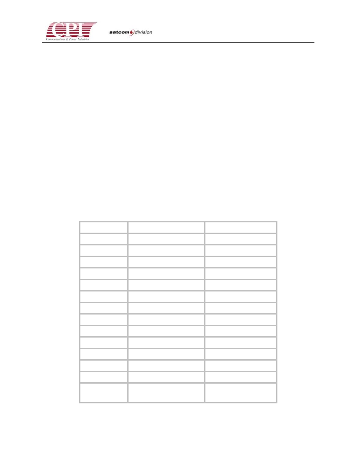
The model numbers, frequency ranges, and rated output power at the waveguide flange of the
high power CHPA series are as follows:
Table 1-1. CHPA Model Number and Frequency Ranges
Model No. Frequency Range (GHz) Rated Power (Watts)
VZC-6967AM 5.850 - 6.725 650
VZC-6967AN 5.850 - 7.075 650
VZC-6967AT 5.850 - 6.650 650
VZC-6967AD 5.715 - 6.425 602
VZC-6967AB 5.850 - 6.650 602
VZC-6967AG 5.850 - 7.075 602
VZC-6967AJ 5.725 - 6.725 602
VZC-6967AH 6.425 - 7.100 650
VZU-6996AB 12.75 - 14.50 501
VZU-6997AB 12.75 - 14.50 650
VZU-6997AC 13.75 - 14.50 602
VZU-6996AC 13.75 - 14.50 501
VZU-6997AE 14.00 - 14.80 602
OC.01023245 REV.K
D
VZU-6997AG 14.70 - 15.32 602
(549 above 15GHz)
THIS DOCUMENT IS THE PROPERTY OF COMMUNICATIONS & POWER INDUSTRIES.
REPRODUCTION OR RELEASE WITHOUT EXPRESS PERMISSION IS STRICTLY PROHIBITED
1-1
Page 20
CHPA SERIES
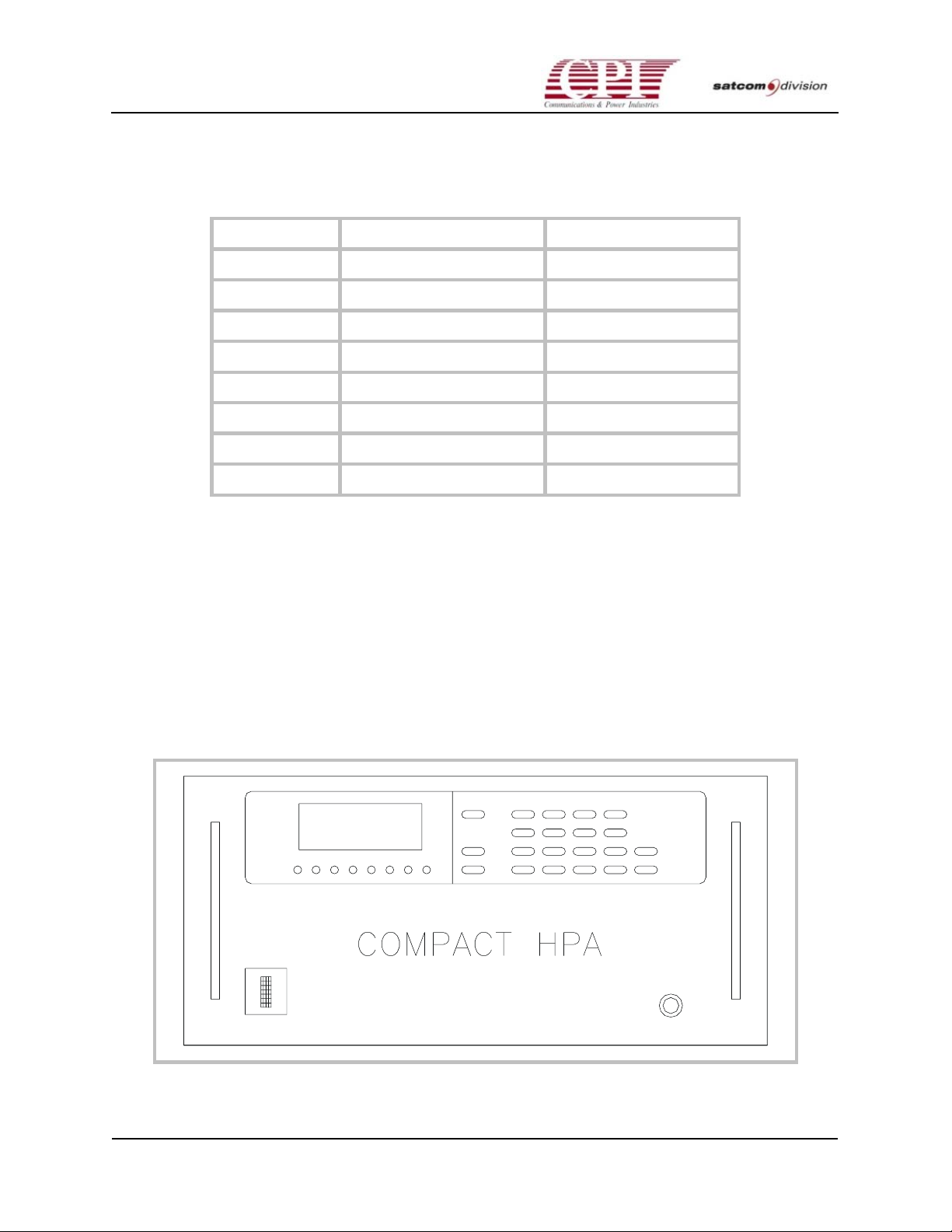
Table 1-1. CHPA Model Number and Frequency Ranges (continued)
Model No. Frequency Range (GHz) Rated Power (Watts)
VZU-6997AA 13.00 - 13.25 602
VZU-6997AD 13.75 - 14.50 650
VZU-6997AJ 12.75 - 13.25 650
VZU-6995AY 17.30 - 18.40 407
VZU-6996AY 17.30 - 17.80 501
VZU-6997CY 17.30 - 18.40 650
VZU-6997AX 17.30 - 18.40 624
VZU-6997AY 17.30 - 18.10 624
The CHPA series has been specifically designed for enhanced performance and ease of
operation. In addition, the CHPA incorporates the use of a microprocessor control system,
thereby simplifying interfacing with remote control and monitor facilities. Flash RAM allows
firmware updates to be made without opening the unit. Implementation of a compact,
lightweight, wideband TWT (traveling wave tube) permits continuous, efficient use across the
entire frequency band. The CHPA also supports the unique internal linearizer, which can be
controlled from the front panel, optional remote panel, and serial computer interface.
Design of the CHPA is also based on the extensive use of LRUs (line replaceable units).
Comprehensive diagnostic procedures allow field personnel to quickly isolate a faulty LRU;
extensive use of captive hardware on the LRU helps to speed the replacement of the LRU so
that the CHPA can be returned to service with a minimum of downtime.
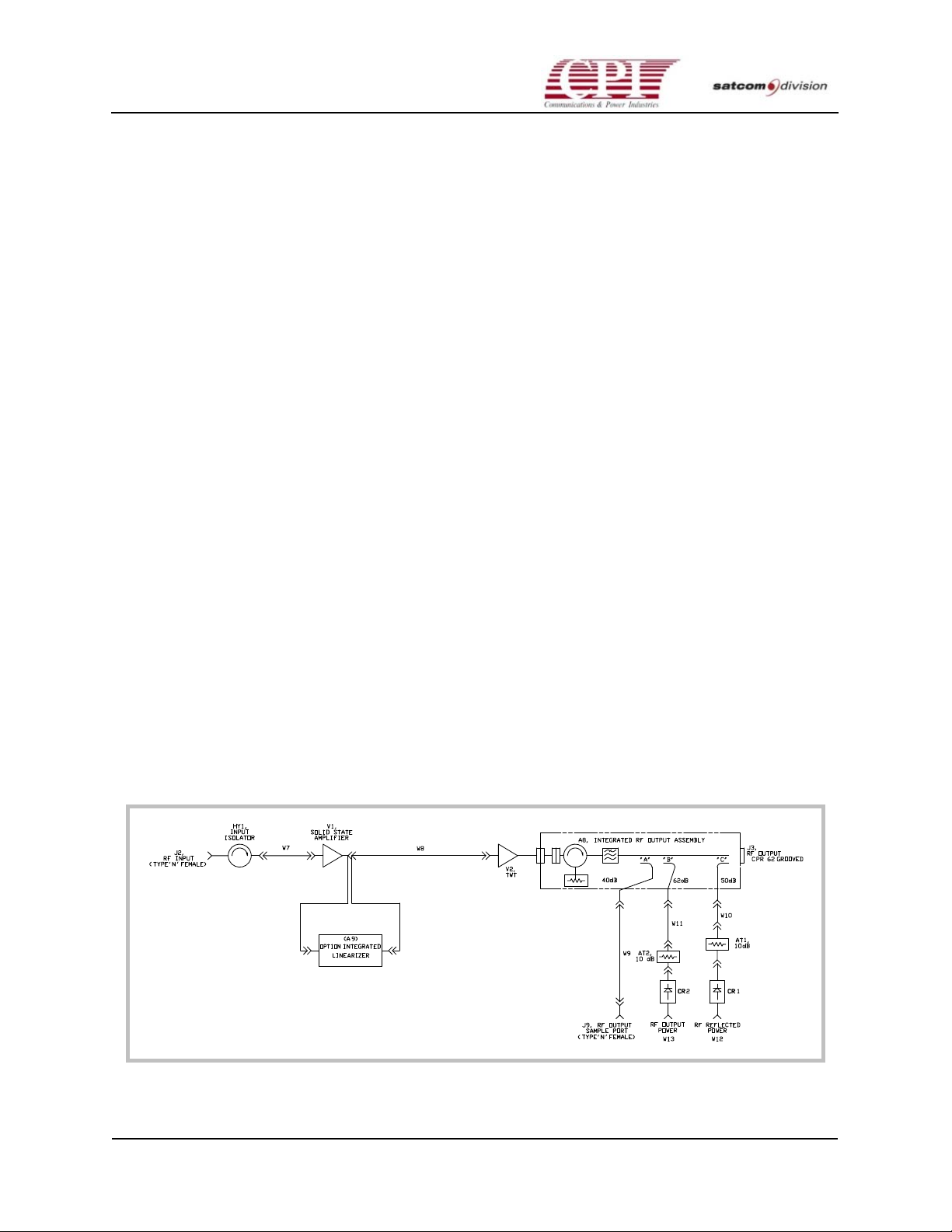
Figure 1-1. The CHPA
1-2
THIS DOCUMENT IS THE PROPERTY OF COMMUNICATIONS & POWER INDUSTRIES.
REPRODUCTION OR RELEASE WITHOUT EXPRESS PERMISSION IS STRICTLY PROHIBITED
DOC.01023245 REV.K
Page 21

CHPA SERIES
1.2 About This Manual
This manual contains information that describes installation, operation, and maintenance
procedures for the Compact High Power Amplifier (CHPA) series. Because specialized training
is required for some phases of installation and repair, certain parts of this manual are directed
only to trained personnel. Warnings appear at the appropriate points to caution all users of
potential RF or high-voltage hazards.
Each chapter begins with a clearly marked tab; this allows the reader to have rapid access to a
particular section. A “Contents,” “List of Figures,” and “List of Tables” are included at the
beginning of the manual for reference to each section.
Chapter 1, “Introduction,” contains a brief overall description and a detailed technical
description of the CHPA. The design philosophy and a brief description of the optional features
are also included in this chapter.
Chapter 2, “Unpacking and Installation,” contains procedures for preparing the site for
installation and unpacking the CHPA. It also describes the steps required to make the
necessary power connections.
Chapter 3, “Interfaces,” describes the CHPA’s built-in interfaces to external devices; also listed
are detailed descriptions for each connection. The communication protocol and command set
used for computer control of the CHPA are also included in this chapter.
Chapter 4, “Initial Power-On and Checkout,” describes the TWT (traveling wave tube)
preconditioning procedures, use of the Front Panel to start up and check out the CHPA, and
instructions for configuring the CHPA for the particular site installation; this includes setting
serial port parameters.
Chapter 5, “Operation,” contains procedures for normal start-up, shutdown, and detailed
operational modes of the CHPA.
Chapter 6, “Maintenance,” contains procedures for scheduled maintenance; also explained are
fault and alarm conditions.
Chapter 7, “Drawings and Schematics,” contains drawings of the various frequency band
CHPAs. It also includes detailed RF schematics and an overall system interconnect drawing.
Chapter 8, “Supplementary Data,” consists of five appendixes; contained are detailed
specifications for the CHPA, a listing of control and display functions, and a summary of
optional features that are available from CPI. Also contained are service and warranty
information and a list of replaceable parts.
OC.01023245 REV.K
D
THIS DOCUMENT IS THE PROPERTY OF COMMUNICATIONS & POWER INDUSTRIES.
REPRODUCTION OR RELEASE WITHOUT EXPRESS PERMISSION IS STRICTLY PROHIBITED
1-3
Page 22
CHPA SERIES
1.3 Major Subsystems and Their Functions
The CHPA (Figure 1-1) is packaged in an 8.75-inch-tall slide-mounted drawer suitable for
standard 19-inch rack mounting. This enclosed assembly houses both the RF and power supply
sections. The overall amplifier enclosure measures approximately 19" (w) x 8.75" (h) x 24" (d),
plus fan and external air duct adapters, and weighs approximately 90 lb.
The RF section includes the TWT (traveling wave tube), SSIPA (solid-state intermediate power
amplifier) with integrated PIN diode attenuator, input/output isolation circuits, RF detectors,
and output filter.
The power supply section includes the power factor correction, power processor, and highvoltage regulation circuitry as well as monitor and control circuitry.
Microprocessor circuits provide automatic sequencing to control both CHPA operation and
continuous monitoring of critical parameters.
The front panel of the unit serves as the primary user interface housing all monitor and control
functions including a type “N” RF connector to sample and measure output RF power.
Protection circuits are included to permit safe, efficient, and reliable operation of the CHPA.
Detailed specifications for the CHPA are provided in Appendix A of Chapter 8,
“Supplementary Data.”
1.4 Technical Description
1.4.1 RF Subsystem
A conservative, field-proven approach is used in the CHPA RF subsystem. The RF block
diagram (Figure 1-2) identifies all major circuit elements for this technical description.
1-4
Figure 1-2. CHPA RF Diagram
THIS DOCUMENT IS THE PROPERTY OF COMMUNICATIONS & POWER INDUSTRIES.
REPRODUCTION OR RELEASE WITHOUT EXPRESS PERMISSION IS STRICTLY PROHIBITED
DOC.01023245 REV.K
Page 23

CHPA SERIES
A low-level RF input signal is applied to the CHPA via a type “N” connector (isolator) located
at the rear of the enclosure. The isolator limits the input voltage standing wave ratio (VSWR) to
a level of 1.3:1 or less back to the source. The RF input is then routed to the SSIPA, which
includes an integrated PIN diode attenuator. The attenuator, controlled via the front panel, has
a control range of a nominal 20 dB with quick response and excellent linearity. Built-in memory
circuits are provided to return the attenuator to a previously set level in the event of prime
power outages.
The SSIPA is designed to be transparent to final amplifier RF parameters and is temperature
compensated to minimize drift. As a result, the overall TWT CHPA gain is specified to be
stable within ± 0.25 dB/24 hours with 10 percent line voltage variations. The output of the
SSIPA is connected to an isolator that protects the SSIPA from TWT failure. The SSIPA and
TWT provide a combined subsystem gain of at least 75 dB at maximum rated power for the Cband and 75 dB for the Ku-band.
The TWTs employed in this power amplifier feature air-cooled, dual depressed collectors for
efficient operation, and periodic permanent magnet (PPM) focused helix design. They are
designed especially for compact, lightweight applications involving satellite uplink service. The
output waveguide assembly interfaces to the TWT and protects the tube from abnormal or
transient conditions that could permanently damage the TWT. This assembly consists of a fourport circulator, harmonic filter, receive reject filter, and three-port directional coupler. The
high-power isolator provides a low VSWR to the external waveguide run and antenna feed.
The isolator assists in protecting the TWT from excessive reflected power due to
damaged/broken waveguides or antenna components. The isolator is rated such that it will
safely dissipate all reflected power equal to the full rated output of the CHPA for the duration
of time until the protection circuits shut off the high-voltage power supplies. In addition, the
isolator is designed such that it can safely dissipate a VSWR mismatch of 2.0:1 (12 percent of
forward RF power) indefinitely.
The harmonic filter contained in the output waveguide assembly provides a minimum of 60 dB
attenuation at the second harmonic and 45 dB attenuation at the third harmonic. The receive
reject filter serves as a high-pass filter cutting off below-band signals. Finally, the three-port
directional coupler provides one reflected power port coupled via a detector to the RF power
monitor assembly for reverse power protection, and two for forward power: one for the user to
monitor forward RF power via a type “N” connector on the front panel, and one for use by the
optional forward power metering circuit, which uses a similar detector to process the RF signal.
The RF sample port, calibrated in coupling ratio versus frequency, permits independent
monitoring of CHPA output power levels through the use of an external spectrum analyzer or
portable power meter. High reflected RF protection circuitry is standard, and reflected power
information is sent to the front panel for display. User-settable low and high RF power alarms
are also available.
The output and reflected power level readouts are also available for remote monitoring via the
optional CPI remote control panel or via the Computer Interface (CIF) port located at the rear of
the enclosure. The RF drive is adjustable via the Serial Remote and CIF port. Also, the RF
sample port, calibrated in coupling ratio versus frequency, permits independent monitoring of
CHPA output power levels through the use of an external spectrum analyzer or portable power
meter.
OC.01023245 REV.K
D
THIS DOCUMENT IS THE PROPERTY OF COMMUNICATIONS & POWER INDUSTRIES.
REPRODUCTION OR RELEASE WITHOUT EXPRESS PERMISSION IS STRICTLY PROHIBITED
1-5
Page 24
CHPA SERIES
The standard RF output interface, provided by the user, to connect the CHPA to the external
waveguide run is a CPR-137F (flange) termination for the C-band, and WR-75F for the Ku-band.
1.4.2 Power Supply Subsystem
The power supply portion of the CHPA provides all of the internal voltages necessary to
operate the TWT, RF driver (SSIPA), the forced-air cooling system, and auxiliary circuits for
control, monitoring, and protection of the CHPA. Other than the AC input power, no other
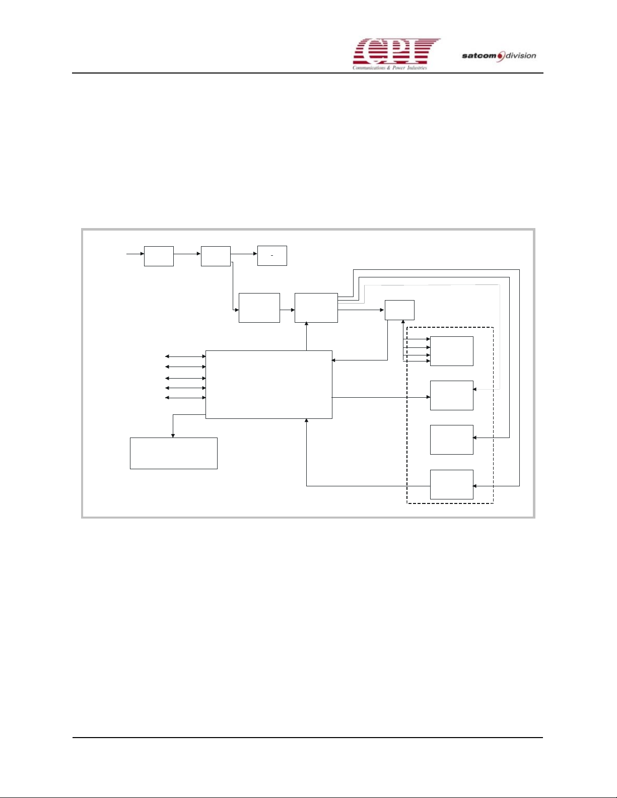
external power supplies or voltages are required for operation. A simplified block diagram of
the power supply is shown in Figure 1-3.
AC
Input
Flash RAM Programming
Serial Remote Control
(For use with CPI Remote Panel)
Switching I/F
Computer I/F
User Interlocks
EMI
Filter
Control
&
Display
Circuit
Breaker
220-240
VAC
Power Factor
Correction
Module
Micro-controller
Fans
375 VDC
Power
Processor
DC Power
RF Metering
& Faults
Control
&
Monitor
Control
HV
Module
Figure 1-3. Power Supply Block Diagram
Helix
Cathode
Coll. 1
Coll. 2
RF Subsystem
TWT
Linearizer
(optional)
SSIPA
RF Monitor
DC
Power
DC
Power
DC
Power
The traveling wave tube derives its operation from four DC power supplies: a low-voltage
filament (heater) supply, a high-voltage helix supply, and two high-voltage collector supplies.
The power supply design utilized in the CHPA is of the SMPC (switch mode power
conditioner) type, which has an excellent reputation for reliability and stability. An added
advantage of the SMPC approach over outdated linear power supplies is its intrinsic high
efficiency and safe operation. By limiting the amount of the instantaneous stored energy in the
power supply, the risk of permanent damage to the CHPA due to abnormal or transient
conditions is avoided. The momentary level of stored energy (measured in joules) is well below
the maximum limit of energy that the tube can safely dissipate during normal operation. The
principal circuit modules are discussed in the following paragraphs.
1-6
THIS DOCUMENT IS THE PROPERTY OF COMMUNICATIONS & POWER INDUSTRIES.
REPRODUCTION OR RELEASE WITHOUT EXPRESS PERMISSION IS STRICTLY PROHIBITED
DOC.01023245 REV.K
Page 25

CHPA SERIES
1.4.3 Power Factor Correction Module
Input primary power––single-phase, 208-240 VAC, 47-63 Hz––flows via an EMI filter and the
main circuit breaker to both the cooling system power supply and the Power Factor Correction
Module. This module provides a regulated 375 VDC to the power processor and allows the
CHPA to meet the requirements of IEC-555 regarding total harmonic distortion.
1.4.4 Power Processor Module
The power processor circuits provide the necessary line and load regulation of the input 375
VDC bus, which is converted via the switch regulator and bridge circuit to a nominal 230 VAC,
25 kHz to drive the high-voltage module. A sample of the helix high-voltage output is returned
to the switch regulator for error feedback correction and sends a pulse-width modulated signal
through an optical isolator to the switching transistors. This approach allows careful regulation
of the TWT helix and collector voltages and protects both supplies from
overvoltage/undervoltage or short-circuit conditions. Low-voltage outputs produced by the
power processor (+/-15 VDC, +5VDC, and 16 VAC) are used to operate various internal circuit
functions as well as provide power for the RF monitor circuit, front panel display, SSIPA, and
optional internal linearizer. Internal sensors provide the necessary over-current protection
functions.
1.4.5 High-Voltage Module
The High-Voltage Module provides the following key power supply functions: regulated TWT
heater supply, regulated TWT high-voltage helix and collector supplies, helix supply
current/voltage monitoring, and fault protection.
The High-Voltage Module contains the transformers, rectifiers, filters, and voltage/current
sense circuits for all critical TWT voltages and currents. The incoming 230 VAC, 25 kHz signal
is applied to the primary of a multi-section high-voltage transformer, which provides all of the
high-voltage levels necessary to operate the traveling wave tube. Since the helix and collectors
share the same transformer and regulator, the high-voltage circuit design establishes the
collector voltages at 52 percent (collector #1) and 26 percent (collector #2) depression below the
helix voltage. This relationship permits optimum efficiency and substantial energy savings
while extending the useful life of the TWT. A separate step-down transformer with rectifier and
filter network operating off the 16 VAC supply is employed to provide the regulated low
voltage to power the TWT heater.
1.4.6 RF Power Monitor Module
The RF power monitor assembly receives signals from the reflected and forward power RF
detectors for use in fault/alarm sensing and power metering. This monitor assembly feeds
voltages to the microprocessor controller; it is the controller that monitors the RF levels to
determine RF high/low faults or high/low alarms. This assembly also contains hardware for
peak measurements. The reflected RF fault sensor protects the TWT against excessive reflected
power due to abnormal waveguide or antenna conditions.
OC.01023245 REV.K
D
THIS DOCUMENT IS THE PROPERTY OF COMMUNICATIONS & POWER INDUSTRIES.
REPRODUCTION OR RELEASE WITHOUT EXPRESS PERMISSION IS STRICTLY PROHIBITED
1-7
Page 26

CHPA SERIES
1.4.7 Control and Display Modules
The Control and Display modules are designed to assure correct operation of the power
amplifier with minimal operator training. These microprocessor-based modules provide
automatic sequencing of CHPA operation and monitoring and control of all critical parameters
via both the front and rear panel interfaces. Flash RAM allows firmware updates to be made
without opening the unit.
The Display Module communicates to the user all necessary information required to monitor
and control the amplifier. Measured readings such as reflected RF power, helix voltage, helix
current, attenuator setting, and forward RF power are all available via the alphanumeric
display. Status LEDs are also included on the panel.
Detailed fault information and user-settable interface parameters are available to the user
through a menu system.
The Control Module is central to the CHPA. All control, input/output, and decision making,
with the exception of critical module, level decisions, is done by the Control Module. All rear
panel user interfaces are also communicated to via the Control Module. To survive AC power
loss, all user settings and operating parameters such as RF trips, TWT operating voltages, serial
port baud rate, and PIN diode attenuation setting, etc., are stored in the battery-backed random
access memory (RAM).
1.5 LRU Philosophy
The maintenance concept employed in the CHPA series is to localize a malfunction or circuit
failure down to the level of an LRU (line replaceable unit), extract the LRU, and replace it with
an equivalent part provided in the spares kit. This procedure can be completed in the field
without resorting to the costly practice of returning the entire CHPA to the depot for servicing.
The philosophy is to configure the LRUs as building blocks with a specific function that can be
monitored by sensors and fault indicators on a real-time basis.
The CHPA contains circuitry to protect itself from operational damage caused by abnormal AC,
DC, RF faults, or insufficient cooling.
Personnel safety is of utmost importance and is safeguarded by proper grounding and also by
access interlocks and covers that prevent physical entry into the high-voltage sections.
1-8
THIS DOCUMENT IS THE PROPERTY OF COMMUNICATIONS & POWER INDUSTRIES.
REPRODUCTION OR RELEASE WITHOUT EXPRESS PERMISSION IS STRICTLY PROHIBITED
DOC.01023245 REV.K
Page 27

CHPA SERIES
1.6 Optional Features
To customize and enhance the functioning of the CHPA, CPI provides a range of options.
These include the following:
• An Internal Linearizer. The internal linearizer extends the linear operating region of the
amplifier. It is easily installed inside the CHPA and is controlled through the front panel,
optional remote panel, and serial computer interface.
• A Separate Remote Control Panel. This Remote panel has identical functions and
configuration as the one supplied with the CHPA.
• Redundant and Power Combined Subsystems. The TWT amplifier can be configured in a
1:1, 1:2, or 1:3 auto switching or power combined configuration as required by the end user.
OC.01023245 REV.K
D
THIS DOCUMENT IS THE PROPERTY OF COMMUNICATIONS & POWER INDUSTRIES.
REPRODUCTION OR RELEASE WITHOUT EXPRESS PERMISSION IS STRICTLY PROHIBITED
1-9
Page 28

CHPA SERIES
This page is intentionally left blank.
1-10
THIS DOCUMENT IS THE PROPERTY OF COMMUNICATIONS & POWER INDUSTRIES.
REPRODUCTION OR RELEASE WITHOUT EXPRESS PERMISSION IS STRICTLY PROHIBITED
DOC.01023245 REV.K
Page 29

2-1
CHPA SERIES
Chapter 2
Unpacking and Installation
2.1 Overview
This chapter contains instructions for site preparation, unpacking, and installation of the
Compact High Power Amplifier (CHPA). Instructions for the optional CHPA Remote Control
and Switching/Power Combined subsystems are supplied separately with those items. The
CHPA’s built-in interface connections for optional equipment are described in Chapter 3,
“Interfaces,” of this manual.
2.2 Pre-Inspection
Inspect the exterior of each for evidence of damage in shipment. If damage seems evident,
immediately contact the carrier that delivered the equipment and submit a damage report.
Failure to do so could invalidate future claims.
2.3 Unpacking
Carefully unpack and remove all items (inspect the interior of the container for damage). Save
all packing material until all inspections are complete. It is recommended that all packing
material be saved for potential future use. Verify that all items listed on the packing slips have
been received.
Inspect all items for evidence of damage in shipment. If damage seems evident, immediately
contact the carrier that delivered the equipment and file a claim. Failure to do so could
invalidate future claims. Check the unit thoroughly for damaged or loose parts. To remove the
top cover of the unit, remove the screws around the sides of the cover and lift the cover off.
After visual inspection is complete, reinstall the cover and carefully tighten all screws.
OC.01023245 REV.K
D
THIS DOCUMENT IS THE PROPERTY OF COMMUNICATIONS & POWER INDUSTRIES.
REPRODUCTION OR RELEASE WITHOUT EXPRESS PERMISSION IS STRICTLY PROHIBITED
2-1
Page 30

CHPA SERIES
2.4 Preparing For Installation
It is recommended that an electrical inspection for verification of customer interface connections
be performed before and after the installation of the equipment in its final operational location;
the following basic steps must be completed:
1. Verify proper CHPA RF input and output terminations. (See Warning.)
2. Verify that all CHPA user interface connectors to be used match pin-out data in Chapter 3,
“Interfaces.”
3. Verify proper prime power connection to the CHPA. See Drawings & Schematics in
Chapter 7, for AC voltage specifications.
Warning: Operating the Compact High Power Amplifier (CHPA) without
proper termination or under excessive load voltage standing wave ratio
(VSWR) could cause destruction of the traveling wave tube (TWT) and will
void the warranty. (See specifications in See Drawings & Schematics in
Chapter 7.)
2.5 Installation
Installation of the CHPA includes four phases:
• Mechanical installation
• Electrical connections
• RF connections
• Cooling considerations
2.5.1 Mechanical Installation
The CHPA is designed for rack slide mounting in a standard 19-inch (48.3 cm) wide rack
cabinet. Use the following procedure for this installation:
1. Determine the required front panel arrangement and exact panel locations for the CHPA on
the rack cabinet.
2. Mount the mating slides (supplied) to the rack cabinet using the supplied hardware.
3. Install the CHPA on the mating slides and securely fasten the front panel to the rack cabinet
rails.
Once the unit is installed on the slides and fastened to the cabinet, the balance of the installation
procedures can be completed.
2-2
THIS DOCUMENT IS THE PROPERTY OF COMMUNICATIONS & POWER INDUSTRIES.
REPRODUCTION OR RELEASE WITHOUT EXPRESS PERMISSION IS STRICTLY PROHIBITED
DOC.01023245 REV.K
Page 31
CHPA SERIES
2.5.2 Electrical Connections
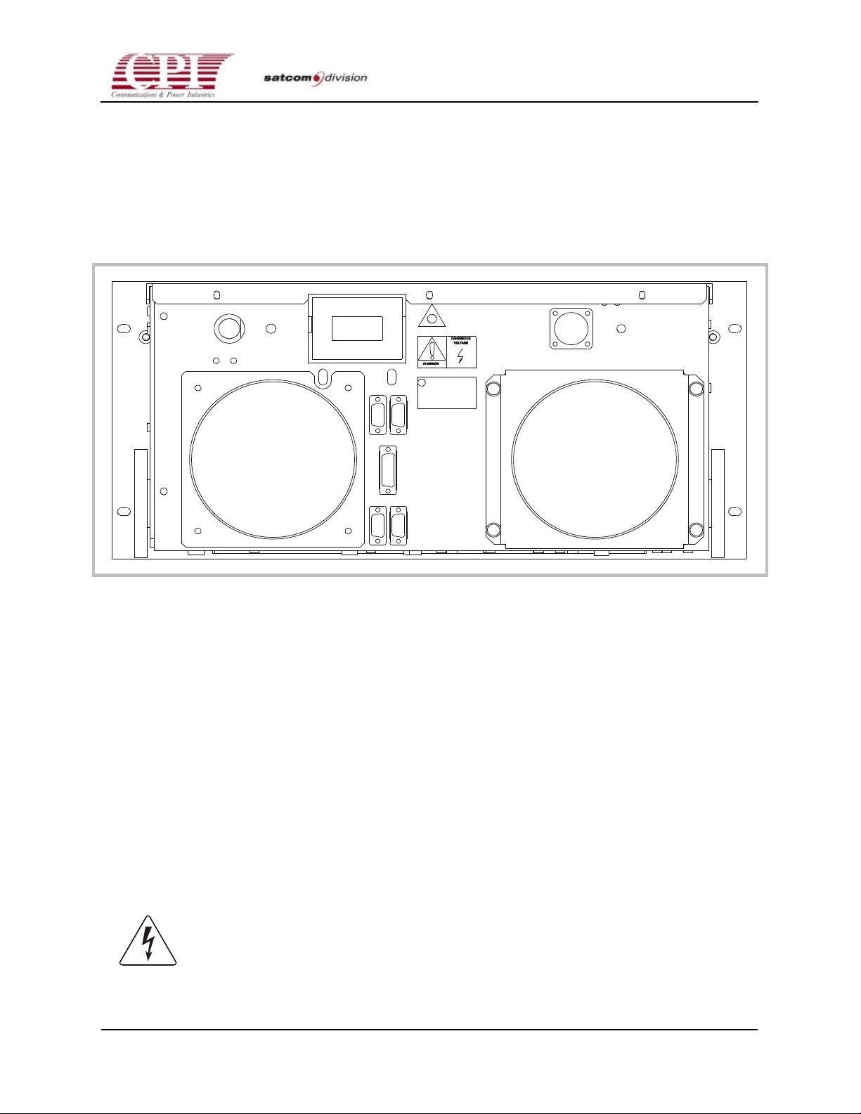
The locations of the connectors referred to in this section are shown in Figure 2-1. Electrical
interconnections to the system consist of prime power, ground strap, and external connections
including computer interface (CIF), remote control, switch interface, and user interlocks, if
applicable. The auxiliary serial port is used for Flash RAM programming and is connected only
during programming.
Figure 2-1. Rear Panel of CHPA
2.5.3 Prime Power
The prime power requirement for the equipment is nominal 208-240 VAC, 47-63 Hz, singlephase. The wiring used for applying prime power to the system should be sized in accordance
with National Electrical Code considering the total input power required. (See Specifications in
See Drawings & Schematics in Chapter 7.)
Prime power is applied to connector J1 located on the rear panel of the CHPA via the connector
provided. The wiring used should be HAR type. The pins of the prime power connector should
be wired as follows:
Pin A—line
Pin B—neutral
Pin C—ground
WARNING! AC PRIME POWER MUST BE REMOVED VIA AN EXTERNAL CIRCUIT
BREAKER BEFORE DISCONNECTING OR CONNECTING THE PRIME POWER
CONNECTOR ON THE CHPA. DO NOT APPLY POWER TO THE CHPA UNTIL
COMPLETION OF THE INSTALLATION.
OC.01023245 REV.K
D
THIS DOCUMENT IS THE PROPERTY OF COMMUNICATIONS & POWER INDUSTRIES.
REPRODUCTION OR RELEASE WITHOUT EXPRESS PERMISSION IS STRICTLY PROHIBITED
2-3
Page 32
CHPA SERIES
2.5.4 Grounding
Note: Proper grounding of the CHPA amplifier to the station ground buss
or to earth ground is necessary for personnel and equipment safety. The
ground screw on the CHPA rear panel must be used for this purpose.
2.5.5 I/O Interfaces
I/O interface connections are made at the rear panel of the CHPA via J4-J8, which are all
standard D-shell connectors. All of the D-shell connectors (except J8) on the rear panel of the
CHPA are female or “socket,” meaning that interface cables constructed by the user must utilize
male or “pin” gender D-shell connectors. Shielded cables should be used with these interfaces.
For best EMI performance, use metal shell connectors and connect the cable shield directly to
the connector shell. (Refer to Chapter 3, “Interfaces,” for pin-out information.)
• Switch Port (J5) 15-pin
• Serial Remote Control (J6) 9-pin
• Computer I/F (J7) 9-pin
• User Interlock (J8) 9-pin
• Aux Serial Port (J10) 9-pin
Note: Connectors J5 and J8 are shipped with jumper interlock connectors
attached. These jumpers are explained in Chapter 3; do not remove them
until you have read that chapter.
Note: Install 9-pin M-F adapter connector (part of ship kit) to CIF port (J7).
2.5.6 RF Connections
The following two RF connections are made at the rear of the CHPA:
• RF Input (J2)—Type “N” female provided. User needs type “N” male on interface
connection.
• RF Output (J3)—Either a CPR-137 (C-band), WR-75 (Ku-band), WR-62 (high Ku-band)
waveguide flange. See details below.
• The following (optional) RF connection is made on the front panel of the CHPA:
• RF Output (sample) Monitor—Type “N” female provided. User needs type “N” male on
interface connection.
2-4
THIS DOCUMENT IS THE PROPERTY OF COMMUNICATIONS & POWER INDUSTRIES.
REPRODUCTION OR RELEASE WITHOUT EXPRESS PERMISSION IS STRICTLY PROHIBITED
DOC.01023245 REV.K
Page 33

CHPA SERIES
2.5.7 RF Output (Waveguide Connection)(J3)
The output waveguide flange of the CHPA is located on the rear panel of the CHPA. The
standard RF output interface, provided by the user, to connect the CHPA to the external
waveguide run is a flange termination. Use the following waveguide flange depending on the
CHPA band:
• CPR-137 for C-band
• WR-75 for Ku-band
• WR-62 for high Ku-band (typically used for DBS applications).
The CHPA comes equipped with a grooved, threaded rear connector. An O-ring gasket is
supplied in the ship kit.
To install the waveguide flange, proceed as follows:
1. Install the O-ring gasket (supplied) in the output flange of the CHPA.
2. Position the interconnecting waveguide so that it aligns precisely with the waveguide flange
at the rear of the CHPA.
3. If alignment is not precise, or if the installation is subject to motion or severe vibration, a
flexible waveguide section should be installed between the output of the CHPA and the
interconnecting waveguide.
4. After alignment is verified in all three planes, loosely attach the interconnecting waveguide
to the output waveguide flange of the CHPA. Start all bolts and verify proper alignment
before uniformly tightening the bolts.
5. Carefully tighten all bolts (in opposite pairs rather than sequentially around the perimeter of
the flange) so that the connection is firm. Do not over tighten because this can strip the
threads or distort the mating flange. Recommended torque is 30 in-lbs for #10-32 (C-band)
and 10 in-lbs for #6-32 (Ku-band).
2.5.8 Cooling Considerations
The CHPA is forced-air cooled. The exhaust air from the CHPA may be at a relatively high
temperature (approximately 35°C above ambient temperature), and heat dissipation may be as
high as 2000 watts. To prevent excessive heat buildup in the rack cabinet, it is recommended
that the exhaust air be ducted away from the CHPA; an air duct is provided for this purpose.
The external ducting must have a cross-sectional area at least equal to that of the exhaust
opening. Minimum airflow required for proper cooling of the CHPA is 120 CFM at sea level
(540 LB/HR). To meet this airflow requirement, external back pressure or intake drag must be
limited to 0.10 inch of water column (0.25 cm). Exhaust duct bends and transitions must be
smooth and bend radii should be as large as possible to promote proper cooling.
OC.01023245 REV.K
D
THIS DOCUMENT IS THE PROPERTY OF COMMUNICATIONS & POWER INDUSTRIES.
REPRODUCTION OR RELEASE WITHOUT EXPRESS PERMISSION IS STRICTLY PROHIBITED
2-5
Page 34

CHPA SERIES
Generally speaking, a 0.10 inch H20 pressure drop in a 5-inch-diameter flex-type hose
corresponds to approximately 10 ft in length. It is therefore recommended that for longer duct
runs, a transition be made to perhaps 8-inch duct as near the CHPA exhaust as possible; 8-inch
plumbing will significantly reduce pressure drop and permit much longer duct runs. Use of 4inch-diameter ducting should be strictly avoided.
It is highly recommended that a heating, ventilation, and air-conditioning (HVAC) engineer be
consulted before ducting is installed as insufficient cooling will significantly impact TWT
(traveling wave tube) longevity.
2-6
THIS DOCUMENT IS THE PROPERTY OF COMMUNICATIONS & POWER INDUSTRIES.
REPRODUCTION OR RELEASE WITHOUT EXPRESS PERMISSION IS STRICTLY PROHIBITED
DOC.01023245 REV.K
Page 35

3-1
CHPA SERIES
Chapter 3
Interfaces
3.1 Overview
Each CHPA is provided with interfaces that can be used to connect it with several optional
external devices. All remote and computer interface cables must be foil or braid-foil shielded to
0
meet EMC/EMI standards. The shields must be connected 360
Pig-tail wiring must not be used. These interfaces are listed below:
• Serial Remote Interface—The default setup for this interface is for connection to a CPI
Remote Control Panel. This port can also be set up for communication with a computer via
a RS-422/485 (4-wire multi-drop) serial link.
to metallic D-sub connectors.
• RF Switch System Interface—This interface enables switch system controllers, such as 1:1
or 1:n, and combiner system controllers to interface with the CHPA.
• External Interlocks Interface—These interlocks enable the user to interlock the CHPA with
external safety devices.
• Computer Interface—This interface enables the user’s computer equipment to control the
CHPA via RS-422/485 or RS-232 serial communication. Users must write all necessary
software for their computers.
• Auxiliary Serial—This RS-232 or RS-422/485 serial port is factory configured for RS-232
operation and is used for Flash RAM programming. Refer to Appendix B for Flash RAM
programming details.
Interface connectors for these devices are located at the rear panel of the CHPA, and are
described in the sections that follow.
3.2 CHPA Control Mode Hierarchy
The Compact High Power Amplifier (CHPA) may be controlled from five points: RF Switch
port, Interlock Interface, Local, Serial Remote, and Computer Interface (CIF). The RF Switch
port and Interlock Interface connect to switching systems and user-defined interlocks. The RF
Switch port and Interlock Interface have the highest level of control. They are active at all times;
all commands that are issued by the user through these ports must be acknowledged and acted
upon if the CHPA may physically do so.
OC.01023245 REV.K
D
THIS DOCUMENT IS THE PROPERTY OF COMMUNICATIONS & POWER INDUSTRIES.
REPRODUCTION OR RELEASE WITHOUT EXPRESS PERMISSION IS STRICTLY PROHIBITED
3-1
Page 36

CHPA SERIES
The Local, Remote, and Computer modes are the main user interface modes.
• All control points will always provide status.
• Front panel push-button labeled LCL/RMT will toggle between all control points. The front
panel is the “super-user” and may transfer the control point at any time.
• If the control point is transferred from the front panel (LOCAL) to the remote panel
(REMOTE) or the CIF, the remote panel may transfer control between itself and CIF.
• No control transfer may be commanded via the CIF port.
3.3 Serial Remote Interface
The CHPA Serial Remote Interface is typically used to support serial communications with a
remote control unit, such as the CPI CHPA Remote unit. This port does support multi-drop RS422/485 (4-wire) serial communications; even at high baud rates (such as 9600 baud) this port
will support communications over a 4000-ft (1200-m) serial cable.
The Serial Remote Interface can be configured for use with the CHPA Remote unit or for use
with a remote computer similar to the CIF port. To configure the port type, press the MENU
button until the selection RMT CONFIGURATION is displayed. PORT TYPE should be
displayed on Line 4 (press the FUNCTION key if it isn’t); use the arrow keys to select either
USER or RMTPNL. RMTPNL will configure the port for the CHPA Remote panel. No other
entries will be available. USER will make the port act similarly to the CIF port. All of the same
protocol and command set choices will be available (press the FUNCTION button to access
these selections). The port will still be subject to the control mode hierarchy described at the
beginning of this section.
The CHPA Serial Remote Interface (J6) is a dual-function port. The user can select one of two
modes: remote panel control mode (RMTPNL) or remote computer control mode (USER). The
CHPA Front Panel controls and indicators are used to configure this port. Selection of
RMTPNL automatically configures the port for “plug and play” operation with a CPI CHPA
Remote Control Panel. In this mode, the remote panel is connected to the port with a “straight”
cable (pin to pin connection) and after connection is immediately available for normal REMOTE
operation. When RMT is selected on the Front Panel of the CHPA (LCL/RMT pushbutton), all
remote control are enabled. Refer to Appendix D for a description of the Remote Control Panel
controls and indicators, and Chapter 5, CHPA Control Modes and Heirachy for more detail on
the remote control operation.
Note: The physical size of the Remote Control Panel is not the same as the
Front Panel of the CHPA.
In the remote computer control mode (USER), this port provides a second computer control
interface that has all of the functions and capability of the “CIF” port (J7). This port supports
multi-drop RS-422/485 (4-wire) serial communciations at high band rates (e.g., 9600 baud) over
a 4000 ft, (1200 m) serial cable.
3-2
THIS DOCUMENT IS THE PROPERTY OF COMMUNICATIONS & POWER INDUSTRIES.
REPRODUCTION OR RELEASE WITHOUT EXPRESS PERMISSION IS STRICTLY PROHIBITED
DOC.01023245 REV.K
Page 37
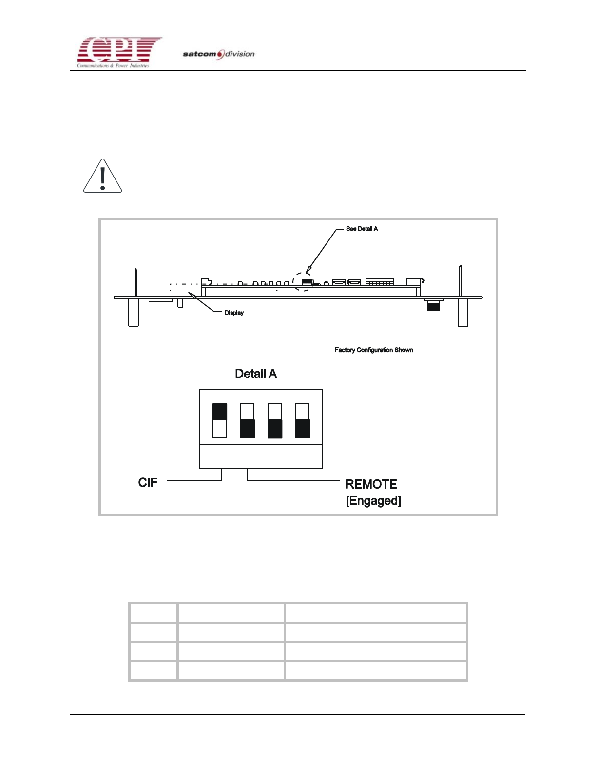
CHPA SERIES
If RMTPNL is selected, no further entries are required. If USER is selected, the port becomes a
second CIF port. When USER is selected, the port must be reconfigurated from the default
(RMTPNL) to a user defined configuration. Refer to Table 3-1 for J6 pin assignments.
Refer to the “Computer Interface” discussion later in this chapter for information on how to
configure J6 for computer control operation.
Note: Use a shielded cable and ground the shield on both ends for
EMC/EMI compliance.
OC.01023245 REV.K
D
Figure 3-1. Setting Termination Resistors
Table 3-1. Serial Remote Interface Pin Assignment (J6)
Pin # Signal Name Remarks
1 Shield Ground
2 Not used
3 Send Data (-) Data sent out of CHPA (RS-422/485)
THIS DOCUMENT IS THE PROPERTY OF COMMUNICATIONS & POWER INDUSTRIES.
REPRODUCTION OR RELEASE WITHOUT EXPRESS PERMISSION IS STRICTLY PROHIBITED
3-3
Page 38
CHPA SERIES
Table 3-1. Serial Remote Interface Pin Assignment (J6) (continued)
Pin # Signal Name Remarks
4 Receive Data (-) Data received by CHPA (RS-422/485)
5 Signal Ground
6 Receive Data (+) Data received by CHPA (RS-422/485)
7 Not used
8 Not used
9 Send Data (+) Data sent out of CHPA (RS-422/485)
Table 3-1 Note:
The Serial Remote Interface uses a protocol and command set very similar to the Computer Interface port. Refer to that portion of
ASCII Byte Decimal Command Defination
\ 92 Set Control Mode. If the CHPA is in either Remote or CIF
this section for programming reference. Additionally, the Serial Remote port includes the following command:
mode, the Serial Remote port may shift control between
Remote and CIF. To specify Remote, follow the command with
the number 0 (ASCII 30 Hex. 48 Dec.); to specify CIF, use the
number 1 (ASCII 31 Hex.49 Dec.).
3.4 RF Switch System Interface
The RF Switch System interface provides the relay-reported CHPA status and RF Inhibit
command required by a waveguide switch controller. Three relays provide CHPA status: Low
RF, Fault, and Sum Fault. The relay coil is de-energized to indicate a condition; this fail-safe
mode means that a loss of power will provide condition indications on all relays. The only
command on this interface, RF Inhibit, is active at all times and is not subject to the control
mode hierarchy. If an RF Switch port RF Inhibit is issued while the low RF Relay indicates a low
RF condition, the Low RF Relay will continue to indicate Low RF. Once the RF Switch Port RF
Inhibit disappears, the Low RF Relay will report existing conditions.
3.4.1 Relay Definitions
The Low RF Relay indicates that the CHPA’s RF output is below the Low RF Alarm level or that
the CHPA is in the Fault state; a waveguide switch system usually uses this information to
trigger automated switching action. The Low RF Relay may be toggled to either Flexible mode
or Rigid mode via the front panel under the RF TRIP LIMITS menu selection. Press the MENU
button until the selection RF TRIP LIMITS is displayed. Press the FUNCTION button until the
selection LOW RF RELAY is displayed; use the arrow keys to select either FLEX (for Flexible
mode) or RIGID (for Rigid mode).
3-4
THIS DOCUMENT IS THE PROPERTY OF COMMUNICATIONS & POWER INDUSTRIES.
REPRODUCTION OR RELEASE WITHOUT EXPRESS PERMISSION IS STRICTLY PROHIBITED
DOC.01023245 REV.K
Page 39
CHPA SERIES
In Rigid mode, the Low RF Relay will indicate that the CHPA’s RF output is below the Low RF
Alarm level any time this condition occurs, except during an RF Switch port RF Inhibit
command. The Rigid mode can be thought of as the strictest operation of the Low RF Relay.
In Flexible mode, the Low RF Relay will indicate that the CHPA’s RF output is below the Low
RF Alarm level any time this condition occurs during the Transmit state, except during any RF
Inhibit, and during Fault state. The Flexible mode allows the user to operate a switch controller
in Automated Switching mode without triggering waveguide switch action while operating the
CHPA in any normal operating state or issuing RF Inhibit commands. Table 3-2 describes the
two modes in more precise detail.
The Fault relay indicates that the CHPA is in the Fault state—the CHPA features Auto Fault
Recycle capabilities and is capable under some circumstances of cycling back to a normal
operating state. This relay may be reassigned to indicate other conditions. Press the MENU
button until the selection RF TRIP LIMITS is displayed. Press the FUNCTION button until the
selection FAULT RELAY is displayed; use the arrow keys to select one the following:
• FAULT—Fault state
• LOW RF—Mimics the action of the Low RF Relay
• SUMFLT—Mimics the action of the Sum Fault Relay
• HV ON—Reports the result of the logical equation: (High Voltage On) and (NOT(RF
Inhibit))
• XMIT—Reports High Voltage ON (See note 6)
The Sum Fault Relay indicates that the CHPA is latched into the Fault state. When the CHPA is
latched into the Fault state, the user must clear the fault source and issue a Reset command to
the CHPA to return it to a normal operating condition.
Table 3-2. Low RF Relay Function
Compact HPA Operational State
HTD Standby BONS
(see note 4)
Transmit
Flexible No LoRF No LoRF No LoRF Yes/No LoRF Yes LoRF
Rigid Yes LoRF Yes LoRF Yes LoRF Yes/No LoRF
Table 3-2 Notes:
1. Yes LoRF= relay de-energized; pin 1 connected to pin 2, pin 3 disconnected from pin 2.
2. No LoRF= relay energized; pin 1 disconnected from pin 2, pin 3 connected to pin 2.
3. If an RF Inhibit is issued from any source except RF Switch Port, Low RF relay=Yes LoRF.
4. BONS is the Beam On Sequence, the time during which the High Voltage turn-on sequence is performed.
5. Fault refers to the Fault state. See Chapter 5 for detailed description.
6. When the amplifier is used in a switching system with switched inputs, the fault relay should be set to “XMIT”.
(see note 4)
Fault
(see note 3)
Yes LoRF
(see note 5)
The RF switch system interface is located at connector J5 on the rear panel of the CHPA. J5 is a
15-pin D-type connector with pin assignments as shown in Table 3-3.
OC.01023245 REV.K
D
THIS DOCUMENT IS THE PROPERTY OF COMMUNICATIONS & POWER INDUSTRIES.
REPRODUCTION OR RELEASE WITHOUT EXPRESS PERMISSION IS STRICTLY PROHIBITED
3-5
Page 40
CHPA SERIES
Table 3-3. RF Switch Pin Assignment (J5)
Pin # Signal Name Remarks
1 Low RF NC Relay NC 1 (Normally closed when coil is de-energized; closed to pi n 2
during Low RF Alarm or the Fault state.)
2 Low RF Common Relay Common 1
3 Low RF NO Relay NO 1 (Normally open when coil is de-energized; open from pin 2
during Low RF Alarm or the Fault state.)
4 Fault NC Relay NC 2 (Normally closed when coil is de-energized; closed to pin 5
during the Fault state or whatever condition chosen for this relay.)
5 Fault Common Relay Common 2
6 Fault NO Relay NO 2 (Normally open when coil i s de-energized; open from pin 5
during the Fault state or whatever condition chosen for this relay.)
7 Not used
8 Not used
9 Sum Fault NC Relay NC 3 (Normally closed when coil is de-energized; closed to pin
10 when the CHPA is latched into the Fault state.)
10 Sum Fault Common Relay Common 3
11 Sum Fault NO Relay NO 3 (Normally open when coil is de-energized; open from pin
10 when the CHPA is latched into the Fault state.)
12 Not used
13 Not used
14 RF Inhibit Closed to pin 15 for “No RF Inhibit.”
15 RF Inhibit Return Input Return
Table 3-3 Notes:
1. Outputs are dry relay contacts rated up to 50 VDC, 50 mA and are connected in fail-safe mode.
2. The RF Inhibit requires a maintained closed-contact with RF Inhibit return and an open circuit for RF Inhibit. For this reason, a
jumper connector is installed and shipped with the unit. When the CHPA is used in a switching system, this jumper is not
required. This RF Inhibit command is executed regardless of the current control mode.
3.5 External Interlocks Interface
The External Interlocks Interface allows the user to connect the CHPA to external safety
interlocks; this interface features two signals: External Interlock Non-Latching and External
Interlock Latching. External Interlock Non-Latching is RF Inhibit; this command is always
executed. External Interlock Latching is a user-induced fault and, unlike other faults, is not
recycled. These commands are executed by opening the command pin from its return.
3-6
THIS DOCUMENT IS THE PROPERTY OF COMMUNICATIONS & POWER INDUSTRIES.
REPRODUCTION OR RELEASE WITHOUT EXPRESS PERMISSION IS STRICTLY PROHIBITED
DOC.01023245 REV.K
Page 41
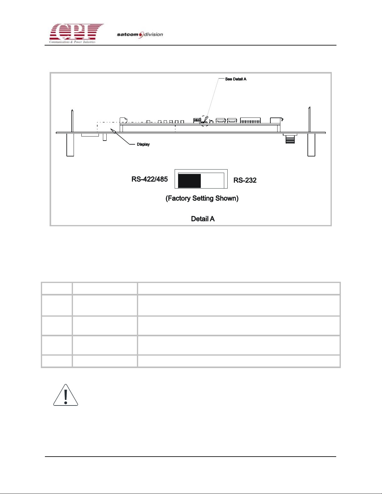
CHPA SERIES
The CHPA External Interlocks Interface is located at connector J8 on the rear panel of the
CHPA. It is a 9-pin D-type connector, with pin assignments as shown in Table 3-4.
Figure 3-2. Setting Serial Format
Table 3-4. Interlocks Interface Pin Assignments (J8)
Pin # Signal Name Remarks
1 External Interlock
Open from Return (pin 2) for External Interlock Fault Latching
(latching beam off)
2 External Interlock
Latching Return
Latching
3 External Interlock
Open from Return (pin 4) for External RF Inhibit
Latching
4 External Interlock Non-Latching Return
Note: A jumper is factory-installed on this port. When using the External
Interlock Interface, this jumper is not required.
OC.01023245 REV.K
D
THIS DOCUMENT IS THE PROPERTY OF COMMUNICATIONS & POWER INDUSTRIES.
REPRODUCTION OR RELEASE WITHOUT EXPRESS PERMISSION IS STRICTLY PROHIBITED
3-7
Page 42

CHPA SERIES
3.6 Computer Interface
The Computer Interface (CIF) port is used to control and monitor the CHPA from an external
data terminal or computer with software provided by the user. The CIF port can be configured
to either RS-232 or RS-422/485 (4-wire) serial hardware format. Using the RS-422/485 serial
hardware format allows an addressable multipoint buss to be implemented, providing serial
communications between a computer and up to 16 other RS-422/485 equipped devices.
Serial format selection is made via a slide switch located inside the unit. To change serial
format, first ensure that prime power is not being applied to the CHPA. Next, remove the
CHPA cover and move the internal slide switch to select the desired format. Refer to Figure 3-2.
The software aspect of the CIF port encompasses two standard protocol formats and a
thorough command set. Protocol format and other serial port parameters, such as baud rate, are
configured through the front panel (CIF Configuration menu). The command set includes all
commands and status essential for operating the CHPA. Using the protocol and command set
described later in this section, users can write software for their own computers.
The serial protocol can be factory configured to match that of the lower power (350/400W)
CHPA, so that software drivers need not be re-written for the higher power (600/700W) CHPA.
This accomplished by setting DIP Switch S1 - Switch #2 of the control Interface CCA to the ON
position. Note that there are slight format differences in the attenuator setting and query
commands. Refer to Table 3-7 and 3-8. Also note that DIP switch setting changes do not take
effect until power to the CHPA has been cycled OFF and ON.
3.6.1 CIF Hardware Configuration
The serial interface can be configured to one of two serial hardware formats: RS-232 or RS422/485 (4-wire). A slide switch mounted inside the unit is used to select the hardware format.
The RS-232 serial hardware format is suitable for point-to-point communications over short
distances (50 ft. or 15 m). The RS-422/485 (4-wire) serial hardware format is suitable for either
point-to-point or multi-drop applications over long distances (4000 ft. or 1200 m) provided that
a suitable serial cable is used. Several cable manufacturers offer serial cables specifically
designed for long-distance serial communications applications. For EMI considerations, the
cable shield should be directly attached to the connector shell.
In the multi-drop configuration, up to 16 other addressable RS-422/485 equipped devices may
share the same serial buss. Termination resistors should be installed on the last device on the
buss. If the buss has multiple runs, the terminating resistor should be engaged on the last device
at the end of each run. The CHPA comes from the factory with the CIF termination resistor
disengaged. On the CHPA, the CIF port terminating resistor is installed by turning “ON”
switch 4. Instructions for changing this switch can be found earlier in this chapter under “Serial
Remote Interface.” Refer to Figure 3-1 as well.
The CHPA CIF (Computer Interface) is located at connector J7 at the rear panel of the CHPA. It
is a 9-pin D-type connector, with pin assignments as shown in Table 3-5. A computer may be
connected to the connector using the standard RS-422/485 configuration.
3-8
THIS DOCUMENT IS THE PROPERTY OF COMMUNICATIONS & POWER INDUSTRIES.
REPRODUCTION OR RELEASE WITHOUT EXPRESS PERMISSION IS STRICTLY PROHIBITED
DOC.01023245 REV.K
Page 43
CHPA SERIES
The CIF serial port parameters are set up using the CIF Configuration menu on the front panel.
Refer to Chapter 4, “Initial Power-On and Checkout,” for detailed procedures regarding CIF
serial port setup.
Table 3-5. CIF (Computer Interface) Pin Assignment (J7)
D-shell Pin Number Rear Panel Signal Name Remarks
1 SHIELD
2 TX (RS-232) Data sent out of CHPA
3 RX– (RS-422/485) Data received by CHPA or RX (RS-232)
4 TX– (RS-422/485) Data sent out of CHPA
5 GND
6 TX+ (RS-422/485) Data sent out of CHPA
7 Not connected
8 Not connected
9 RX+ (RS-422/485) Data received by CHPA
3.7 Computer Interface (CIF) Protocol
The following information describes the structure and content of the Computer Interface (CIF)
protocol for the CHPA. The CIF protocol uses ASCII characters in a packet message structure to
provide serial asynchronous communications between a computer and the CHPA. The CIF
protocol includes commands for controlling and monitoring the CHPA. CHPA control
commands are executed by the CHPA if the CIF port has been chosen as the valid control point.
CHPA monitoring commands are valid at all times unless otherwise stated. Use the CIF
Configuration menu to set the desired CIF parameters.
Unless otherwise specified, all numbers in this document are base 10.
3.8 Protocol Message Structure
The CIF protocol uses a packet style message structure. Each packet typically includes a header
byte, address byte, command byte, any necessary parameter byte(s), an ending byte, and a
check byte. In this context, “byte” refers to a message constituent that is composed of 1 start bit,
a 7-bit ASCII character, 1 parity bit (optional), and 1 stop bit. The parity bit will exist if either
Even, Odd, or Mark parity is chosen. No parity bit will be included if None is chosen. Since 7
data bits are used, ASCII characters 0 through 127 are the “alphabet” for all valid messages. To
avoid incompatibilities with existing controllers, the actual alphabet used avoids most control
OC.01023245 REV.K
D
THIS DOCUMENT IS THE PROPERTY OF COMMUNICATIONS & POWER INDUSTRIES.
REPRODUCTION OR RELEASE WITHOUT EXPRESS PERMISSION IS STRICTLY PROHIBITED
3-9
Page 44
CHPA SERIES
characters. The protocol provides choices for header/ending byte format and checksum format,
which are described later in this section.
The user’s computer generates and sends packets to the CHPA that can contain only one
command and associated parameters. The CHPA can process only one received packet at a
time; packets are not queued for processing. If a command is sent to the CHPA CIF port, a
response will be returned usually within 100 ms. Commands requiring long execution times,
such as changing power level, generate an immediate response indicating if the command was
accepted and whether or not execution has begun.
If the CHPA was able to execute a command received via the CIF, the response message will
indicate what command was executed and return any necessary parameters. In the case of a
query command, the returned parameters are referred to as status bytes and are described in
detail later in this section.
If the CHPA was not able to execute a command received via the CIF, a reject code (or codes) is
included in the response message. If the STX/ETX header/ending byte message format was
used, the header byte is NAK, thus indicating a rejection.
3.9 Command and Response Format
Command Received by CHPA
HEADER ADDRESS COMMAND PARAMETERS ENDING CHECK
BYTE BYTE BYTE AS REQUIRED BYTE BYTE
Response Returned When Command is Accepted
HEADER ADDRESS COMMAND PARAMETERS ENDING CHECK
BYTE BYTE BYTE BYTE(S) BYTE BYTE
Response Returned When Command is Rejected
HEADER ADDRESS COMMAND PARAMETERS ENDING CHECK
BYTE BYTE BYTE CODE(S) BYTE BYTE
To avoid problems with control characters, and so on, device addresses, commands,
parameters, and responses are limited to standard ASCII values 32 through 126.
3.9.1 Header and Ending Bytes
(Header and ending bytes are under CIF CONFIGURATION as PROTOCOL.)
Two message formats are supported: STX/ETX header/ending bytes and printable ASCII
header/ending bytes.
STX/ETX option (STX/ETX on front panel)
3-10
THIS DOCUMENT IS THE PROPERTY OF COMMUNICATIONS & POWER INDUSTRIES.
REPRODUCTION OR RELEASE WITHOUT EXPRESS PERMISSION IS STRICTLY PROHIBITED
DOC.01023245 REV.K
Page 45
CHPA SERIES
Commands:
Header byte = STX (ASCII 02)
Ending byte = ETX (ASCII 03)
Responses:
Header byte = ACK (ASCII 06) is used if the CHPA accepted the command.
Header byte = NAK (ASCII 21) is used if the CHPA rejected the command. A reject code (or
codes) indicates why the command was rejected.
Ending byte = ETX (ASCII 03)
ASCII option (ASCII on front panel)
All commands and responses:
Header byte = { (ASCII 123)
Ending byte = } (ASCII 125)
3.9.2 Address Byte
(The address byte is under CIF CONFIGURATION as PORT ADDRESS.)
The address byte provides the computer port with an address. It may be set from 48 to 111
using the keypad or the arrow keys.
3.9.3 Command Byte
The range of command bytes is from 32 to 111.
3.9.4 Response Byte(s)
The response byte(s) range from 32 to 95.
3.9.5 Reject Byte(s)
If a command is not accepted, a reject code (or codes) is returned. See Table 3-6.
Table 3-6. Reject Bytes
ASCII Character Decimal Meaning
a 97 Comm and byte not recognized.
b 98 Ilegal parameter out of range.
c 99 CIF is not enabled and the command can’t be executed.
OC.01023245 REV.K
D
THIS DOCUMENT IS THE PROPERTY OF COMMUNICATIONS & POWER INDUSTRIES.
REPRODUCTION OR RELEASE WITHOUT EXPRESS PERMISSION IS STRICTLY PROHIBITED
3-11
Page 46
CHPA SERIES
Table 3-6. Reject Bytes (continued)
ASCII Character Decimal Meaning
d 100 Slow command in execution
f 102 The command was not executed; high voltage is OFF.
g 103 The command wa s not executed; RF is inhibited.
i 105 The command was not accepted; unit is in Fault.
3.9.6 Check Byte
(Check byte is under CIF CONFIGURATION as CHECKBYTE.)
Two options are available:
Longitudinal Parity—The check byte is the exclusive OR of all message bytes including the
header and ending bytes and excluding CR or LF if chosen. (LONG on front panel.)
Checksum—This formula provides a printable ASCII checksum. (SUM on front panel.)
N
Checksum = 32 + MOD
[(Σ message bytei) – (32 * N)]
95
i=1
where:
• MOD
is the operation modulo 95.
95
• N is the total number of bytes in the message including header and ending bytes and
excluding CR or LF if chosen.
• message byte
is the ith message byte where 1 ≤ i ≤ N.
i
Example: Calculate the check byte for the message {A1} using the checksum rule.
Character: { A 1 }
ASCII: 123 65 49 125
i: 1 2 3 4
Check Byte = 32 + MOD
= 32 + MOD
[234]
95
[(123+65+49+125) – (32*4)]
95
= 32 + 44
= 76 which translates to the ASCII character L
3-12
THIS DOCUMENT IS THE PROPERTY OF COMMUNICATIONS & POWER INDUSTRIES.
REPRODUCTION OR RELEASE WITHOUT EXPRESS PERMISSION IS STRICTLY PROHIBITED
DOC.01023245 REV.K
Page 47

CHPA SERIES
Notes:
1. Parity errors will cause the command to be ignored and no response message to be issued.
2. If any character is received before or during the transmission of a response message, the
response message will be deleted. This will not interfere with the execution of a command.
3. The CIF port can be set to accept bad check bytes (it will expect a character in the check
byte’s place). Press the MENU button to select CIF CONFIGURATION; press the
FUNCTION button to select BAD CHCK BYTE. Use the arrow keys to select the desired
choice—YES will allow the CHPA to accept bad check bytes; NO will prevent the CHPA
from accepting bad check bytes.
3.9.7 Carriage Returns and Line Feeds
The user may choose to use carriage returns (CR) and line feeds (LF); they are appended to the
command/response. If both CR and LF are chosen, they will be appended in the order CR LF.
Be sure that the CIF port’s setting matches the user’s monitor and control computer settings—
mismatches in settings may result in the CHPA providing partial or unexpected responses.
To select CR, press the MENU button to select CIF CONFIGURATION; press the FUNCTION
button to select CR ENABLE. Use the arrow keys to select the desired choice (YES or NO).
To select LF, press the MENU button to select CIF CONFIGURATION; press the FUNCTION
button to select LF ENABLE. Use the arrow keys to select the desired choice (YES or NO).
3.10 Commands
Commands are sent from a computer to the CHPA. Refer to information given earlier in this
section for the proper formats for commands. There are four types of commands:
• Query commands. These commands cause the CHPA to return information. The returned
bytes are called status bytes; they are described in detail later in this section. Refer to Table
3-7.
• CHPA commands. These commands cause the CHPA to take some action. Refer to Table 3-
8.
• Slow commands. A subset of CHPA commands, these commands may require several
seconds to complete. Refer to Table 3-9.
• Interface commands. These commands invoke special interface features. Refer to Table 3-10.
A table for each command type is provided. The tables include the ASCII code associated with
the commands and its base 10 representation, and the command name and a description of the
command.
OC.01023245 REV.K
D
THIS DOCUMENT IS THE PROPERTY OF COMMUNICATIONS & POWER INDUSTRIES.
REPRODUCTION OR RELEASE WITHOUT EXPRESS PERMISSION IS STRICTLY PROHIBITED
3-13
Page 48
CHPA SERIES
Table 3-7. Query Commands
ASCII Byte Decimal Commands
0 48 ID/Version Query. An eight-character string will be returned that identifies the
CHPA model and computer interface version.
1 49 Summary Status Query. Two bytes of status are returned
2 50 Secondary Status Query. Two bytes of status are returned.
3 51 Fault/Miscellaneous Status Query. Four bytes of fault conditions and general
information are returned. The information returned mimics the front panel
report. This query will store faults until a Cancel or Reset from any source
clears all bits.
4 52 Info/Error Data Query. Two bytes are returned that indicate activity since the
last Info/Error Data Query. The response is port sensitive and reflects the
status of the port (Remote or CIF) queried.
5 53 Not used
6 54 RF Output Power in dBm Query. Four ASCII characters in the form NN.N are
returned. Leading zero is replaced with a blank.
7 55 RF Output Power in Watts Query. Four ASCII characters in the form NNNN
are returned. Leading zeros are blanked.
8 56 Attenuator Setting Query. Four ASCII characters in the form NN.N are
(See Note 2)
returned. Leading zero is blanked.
9 57 Not used
: 58 Low RF Alarm Trip-point Query (Watts).
; 59 High RF Alarm Trip-point Query (Watts).
< 60 Low RF Fault Trip-point Query (Watts).
= 61 High RF Fault Trip-point Query (Watts).
(see note 1)
(see note 1)
(see note 1)
(see note 1)
> 62 Meter Query. This command returns meter readings (without the units)
according to the following formats. Leading zeros are replaced with blanks.
Each reading is delimited by a space (ASCII 20 hex 32 dec).
RF Output (dBW) NN.N dBW
RF Output (Watts) NNNN W
Attenuator Setting NN.N dB
(see note 2)
Helix Voltage NN.NN kV
Helix Current NN.N mA
Reflected RF NNN W
Beam Current NNNN mA
? 63 Elapsed Time Query. This command will return the elapsed time meters
separated by a space (ASCII 20 hex 32 dec) Heater Elapsed Time Meter
NNNNNN Beam On Elapsed Time Meter NNNNNN
Table 3-7 Notes:
1. These commands return four ASCII characters in the form NNNN. Leading zeros are blanked.
2. For CHPA Protocol Option, (DIP Switch S1-Switch #2 of Interface CCA is ON) Attenuator Setting is of the form NN.N0 dB.
3-14
THIS DOCUMENT IS THE PROPERTY OF COMMUNICATIONS & POWER INDUSTRIES.
REPRODUCTION OR RELEASE WITHOUT EXPRESS PERMISSION IS STRICTLY PROHIBITED
DOC.01023245 REV.K
Page 49
CHPA SERIES
Table 3-8. CHPA Commands
ASCII Byte Decimal Command Definition
@ 64 Transmit. This command turns the beam on.
A 65 Standby. This command turns the beam off.
B 66 RESET. This command is the equivalent of pushing the CANCEL button on the
front panel.
C 67 Set Attenuator. Provide the attenuator setting in the form NN.N. The interface
will accept leading spaces (ASCII 20 hex 32 dec).
(see note 1) (See Note 4)
D 68 Set RF O/P power in dBm. Provide the setting in the form NN.N. Leading
(see note 1 )
zeros may be replaced with spaces (ASCII 20 hex 32 dec).
E 69 Set RF O/P power in watts. Provide the setting in the form NNNN. Leading
(see note 1 )
zeros may be replaced with spaces (ASCII 20 hex 32 dec).
F 70 Set ALC RF O/P in dBm. This command activates the ALC mode and sets the
power requested. Provide the setting in the form NN.N.
G 71 Set ALC RF O/P in Watts. This command activates the ALC mode and set s
the power requested. Provide the setting in the form NNNN. Leading zeros may
be replaced with blanks.
H 72 Terminate ALC
I 73 Enable RF Inhibit
J 74 Clear RF Inhibit
K 75 Not used
L 76 Set Low RF Alarm Trip-point (Watts).
M 77 Set High RF Alarm Trip-point (Watts).
N 78 Set Low RF Fault Trip-point (Watts).
(see note 2)
(see note 2)
(see notes 2)
O 79 Set High RF Fault Trip-point (Watts).
P 80 Not used
Q 81 Not used
V 86 Set Linearizer.
(see note 3)
To command the linearizer, send gain, phase, and
amplitude setting in the form NNN NNN NNN (each setting is separated by a
space) after V. To lock this setting in, see command X. Set Example: {AV123
211 012} where A is the address.
W 87 Query Linearizer.
(see note 3)
To query the linearizer, send W with no argument.
The response will be in the form NNN NNN NNN (gain, phase, amplitude).
X 88 Lock Linearizer Settings.
(see note 3)
Send this command to lock in (save to nonvolatile memory) linearizer settings. This command should be sent after the
desired linearizer settings have been achieved.
OC.01023245 REV.K
D
THIS DOCUMENT IS THE PROPERTY OF COMMUNICATIONS & POWER INDUSTRIES.
REPRODUCTION OR RELEASE WITHOUT EXPRESS PERMISSION IS STRICTLY PROHIBITED
(see note 2)
3-15
Page 50
CHPA SERIES
Table 3-8. CHPA Commands (continued)
ASCII Byte Decimal Command Definition
a 97 Reset to Defaults. Reset the unit operating state and fault/alarm trip point
values to firmware defaults except Helix Over Voltage, Helix Under Voltage,
and Helix Average Over Current fault trip limits.
Table 3-8 Notes:
1. If the ALC mode is active, it will be terminated.
2. Specify the setting value in the form NNNN (including leading zeros).
3. Linearizer commands are active only if internal linearizer is installed and S1-1 on 01020360 (CCA, Controller Interface) is ON
4. For CHPA Protocol Option (DIP Switch S1- Switch #2 of Interface CCA is ON), Attenuator setting is of the form NN.NO dB.
3.10.1 Slow Commands
A subset of CHPA commands, these commands may require several seconds to complete. These
commands are listed in the CHPA commands table (Table 3-8).
Table 3-9. Slow Commands
ASCII Byte Decimal Commands (for description and note, see Table 3-8)
D 68 Set RF O/P power in dBm.
E 69 Set RF O/P power in Watts.
(see note 1)
(see note 1)
F 70 Set ALC RF O/P in dBm.
G 71 Set ALC RF O/P in watts.
Table 3-10. Interface Commands
ASCII Byte Decimal Command Definition
R 82 Enable RF Limits. RF O/P power commands will be rejected (reject code “b”) if
they exceed the Low RF Fault or High RF Fault Trip settings.
S 83 Disable RF Limits. Cancels the Enable RF Limits command.
T 84 Not used
U 85 Not used
3-16
THIS DOCUMENT IS THE PROPERTY OF COMMUNICATIONS & POWER INDUSTRIES.
REPRODUCTION OR RELEASE WITHOUT EXPRESS PERMISSION IS STRICTLY PROHIBITED
DOC.01023245 REV.K
Page 51
CHPA SERIES
3.11 Status Byte Definitions
Status bytes are the responses to Query commands. Each bit represents some piece of
information; the bit definitions are provided in Tables 3-11 to 3-14. Bit 0 corresponds to the least
significant bit (LSB) and bit 7 corresponds to the most significant bit (MSB). Bit 7 will contain
the parity bit, if chosen. To make all status bytes printable ASCII characters, bit 6 is always
equal to the complement of bit 5.
Table 3-11. Summary Status Bytes
Byte Bit Bit Definition
1
2
7(MSB) Parity
6 Complement of bit 5
5 Change bit. This bit is set if the current power level differs by more than 0.1 dB from the
value returned by the last successful RF power query. This bit is zero if RF is inhibited
or if the CHPA is in Standby. The value of this bit is determined each time a Summary
Status Query is requested.
4 Info/Error Message Data Check. This bit is set when a selected information or error
condition has occurred. This bit is cleared by an Info/Error Message Query command.
Refer to Interface commands, Activate Info/Error Message command, and Deactivate
Info/Error Message command.
3 Secondary Status Data Check. This bit is set when any change in a Secondary Status
byte occurs. This bit is cleared by a Secondary Status Query.
2 Fault/Misc Status Data Check. This bit is set when any change in a Fault/Misc status
byte occurs. This bit is cleared by a Fault/Misc Status Query.
1 ALC active. This bit is set when ALC is active.
0(LSB) Slow Command in Execution. This bit is set during the execution of a Slow command.
Refer to Table 3-9.
7(MSB) Parity
6 Complement of bit 5
5 RF Inhibited. Bit is set if RF is inhibited.
4 Transmit Selected. Bit is set if Transmit is selected during Heater Time Delay.
3 Summary Fault. Bit is set if CHPA is latched into the Fault state.
2 CHPA Operating State
1 CHPA Operating State
0(LSB) CHPA Operating State
OC.01023245 REV.K
D
(see note 1)
(see note 1)
(see note 1)
THIS DOCUMENT IS THE PROPERTY OF COMMUNICATIONS & POWER INDUSTRIES.
REPRODUCTION OR RELEASE WITHOUT EXPRESS PERMISSION IS STRICTLY PROHIBITED
3-17
Page 52
CHPA SERIES
Table 3-11 Notes:
1. CHPA Operating State is indicated as follows:
2 1 0 CHPA State
0 0 0 Not used
0 0 1 Heater Time Delay
0 1 0 Standby
0 1 1 Beam On Sequence
1 0 0 Beam On
1 0 1 Beam On and RF Inhibited
1 1 0 Beam Off Sequence
1 1 1 Fault
Table 3-12. Secondary Status Bytes
Byte Bit Bit Definition
1
2
7(MSB) Parity
6 Complement of bit 5
5
4
Valid control point
Valid control point
Bit 5 Bit 4 Control Point
0 0 Local
1 0 Remote
1 1 Computer Interface (CIF)
3 BB-RAM Error Detected. This bit is set if the battery-backe d RAM contents are
suspected to be corrupt. This condition usually indicates that the BB-RAM must be
replaced. Under this circumstance, firmware defaults are used for all alarm and fault
settings.
2 Not used
1 High RF Alarm. This bit is set during High RF Alarm.
0(LSB) Low RF Alarm. This bit is set during Low RF Alarm.
7(MSB) Parity
6 Complement of bit 5
5 RF Peak Output Power. This bit is set if power meter is detecting peak power.
3-18
4 Not used
3 Power Fail Signal Timeout. This bit is set if the AC Power Fail signal is detected true
for more than 10 seconds and corresponds to the front panel “PFAL” report.
2 Not used
1 Not used
0(LSB) Not used
THIS DOCUMENT IS THE PROPERTY OF COMMUNICATIONS & POWER INDUSTRIES.
REPRODUCTION OR RELEASE WITHOUT EXPRESS PERMISSION IS STRICTLY PROHIBITED
DOC.01023245 REV.K
Page 53
Table 3-13. Fault and Miscellaneous Status
Byte Bit Bit Definition
CHPA SERIES
1
2
7(MSB) Parity
6 Complement of bit 5
5 Helix Over Voltage
4 Helix Under Voltage
3 Helix Average Over Current
2 Power Supply Arc Trip
1 DC Buss Under Voltage
0(LSB) Helix Voltage Detected in Standby
7(MSB) Parity
6 Complement of bit 5
5 Reflected RF
4 PS Thermal/Interlocks Open
3 TWT Thermal Fault
2 High RF Fault
1 Low RF Fault
0(LSB) External Interlock Fault
3
7(MSB) Parity
6 Complement of bit 5
5 Not used
4 Not used
3 Not used
2 Not used
1 Not used (this was originally Low Airflow Fault)
0(LSB) SSIPA Over Current Fault
OC.01023245 REV.K
D
THIS DOCUMENT IS THE PROPERTY OF COMMUNICATIONS & POWER INDUSTRIES.
REPRODUCTION OR RELEASE WITHOUT EXPRESS PERMISSION IS STRICTLY PROHIBITED
3-19
Page 54
CHPA SERIES
Table 3-13. Fault and Miscellaneous Status (continued)
Byte Bit Bit Definition
4
7(MSB) Parity
6 Complement of bit 5
5 RF Inhibit—Switch Port
4 RF Inhibit—External Interlock
3 RF Inhibit—CIF
2 RF Inhibit—Local
1 RF Inhibit—Remote Panel
0(LSB) Not used
Table 3-13 Note:
*Bit is set for the fault condition.
Table 3-14. Information/Error Messages
(Response is port sensitive and will reflect the status of the port [Remote or CIF] queried.)
Byte Bit Bit Definition (set if condition exists since last query)
1
7(MSB) Parity
3-20
6 Complement of bit 5
5 Control of the CHPA has been given to the computer interface.
4 Control of the CHPA has been lost by the computer interface.
3 An illegal or bad character has been received by CIF.
2 A CIF response message was interrupted because activity was detected on the CIF
port.
1 Not used
0(LSB) Not used
THIS DOCUMENT IS THE PROPERTY OF COMMUNICATIONS & POWER INDUSTRIES.
REPRODUCTION OR RELEASE WITHOUT EXPRESS PERMISSION IS STRICTLY PROHIBITED
DOC.01023245 REV.K
Page 55
Table 3-14. Information/Error Messages (continued)
Byte Bit Bit Definition (set if condition exists since last query)
CHPA SERIES
2
7(MSB) Parity
6 Complement of bit 5
5 RF O/P power setting command terminated due to the cessation of high voltage.
4 RF O/P power setting command terminated before reaching requested value.
3 ALC activity terminated due to cessation of high voltage.
2 Not used
1 Not used
0(LSB) Not used
3.12 ID/Version Message
The ID/Version Message is returned upon receiving the ID/Version Query and consists of the
following string, where x is a variable:
VZCHPAxn
x – miscellaneous character
n – Computer Protocol Version. The first version used with the CHPA is labeled A.
OC.01023245 REV.K
D
THIS DOCUMENT IS THE PROPERTY OF COMMUNICATIONS & POWER INDUSTRIES.
REPRODUCTION OR RELEASE WITHOUT EXPRESS PERMISSION IS STRICTLY PROHIBITED
3-21
Page 56

CHPA SERIES
This page is intentionally left blank.
3-22
THIS DOCUMENT IS THE PROPERTY OF COMMUNICATIONS & POWER INDUSTRIES.
REPRODUCTION OR RELEASE WITHOUT EXPRESS PERMISSION IS STRICTLY PROHIBITED
DOC.01023245 REV.K
Page 57
4-1
CHPA SERIES
Chapter 4
Initial Power On and Checkout
4.1 Overview
This chapter describes the procedures for turning on the CHPA for the first time. It also
describes the steps for initial checkout of the system, and for setup of the Remote and Computer
Interface (CIF) serial ports.
Before proceeding with the steps in this chapter, read it completely. Also read the next chapter,
“Operation,” to become familiar with normal operation of the CHPA.
Warning: The information presented in this chapter is addressed to
technicians who have specific training in, and knowledge of, high-power
amplifiers. Inappropriate use of the CHPA can cause harm to the operator
or equipment. Do not attempt the procedures outlined in this chapter
before becoming thoroughly familiar with its contents.
4.2 Pre-Power Procedures
Before applying prime AC power to the CHPA, verify that the following conditions are met:
• The voltage of the station’s AC prime power matches those marked on the back label (208-
240 VAC).
• A ground strap is connected from the station’s ground buss to the ground screw located on
the CHPA’s back panel.
• All connections are tight, no wires are pinched, and no other hardware or circuit-card
assemblies have been loosened during shipment or handling.
• The main power switch on the CHPA front panel is turned off.
• The RF input and RF output are connected to a matched source and test load.
Note: Failure to verify these pre-power conditions may damage the CHPA
or cause it to malfunction. Operating the equipment before verifying these
items may also void the warranty.
OC.01023245 REV.K
D
THIS DOCUMENT IS THE PROPERTY OF COMMUNICATIONS & POWER INDUSTRIES.
REPRODUCTION OR RELEASE WITHOUT EXPRESS PERMISSION IS STRICTLY PROHIBITED
4-1
Page 58
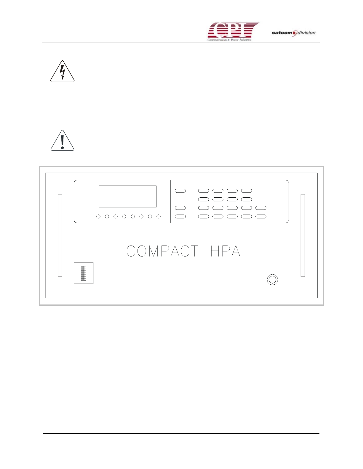
CHPA SERIES
WARNING! LETHAL VOLTAGES OF UP TO 13 KVDC ARE PRESENT INSIDE THE
CHPA WHEN POWER IS APPLIED TO THE SYSTEM. ALWAYS TURN POWER OFF
BEFORE SERVICING THE CHPA. DO NOT ATTEMPT TO REPAIR THE CHPA
UNLESS EXPERIENCED IN SERVICING BOTH MICROWAVE AND HIGH-VOLTAGE
SYSTEMS. SHOULD THE CHPA FAIL DURING OR AFTER INITIAL POWER-ON,
REFER TO CHAPTER 6 “MAINTENANCE”. IF NECESSARY, ALSO SEE APPENDIX
D, "WARRANTY/ SUPPORT INFORMATION," IN CHAPTER 8, "SUPPLEMENTARY
DATA."
Note: Before switching on power for the first time, become familiar with all
CHPA controls and indicators, and with the procedures in this chapter.
Figure 4-1. The CHPA Series Front Panel
4.3 Using the Front Panel
The CHPA is fully controlled using the front panel; this panel is also used to display (and in
some cases to change) the CHPA’s RF power-level settings, protection settings, and computer
interface and configuration settings. (Refer to Figure 4-1, which shows the front panel layout.)
Because the front panel is used to perform initial power-on and checkout of the CHPA,
familiarity with its functioning is essential. This section provides a brief overview sufficient for
normal start-up tasks. For more complete information, see Chapter 5, “Operation”; also see
Appendix B, “Control Appearance and Content,” in Chapter 8, “Supplementary Data.”
4-2
THIS DOCUMENT IS THE PROPERTY OF COMMUNICATIONS & POWER INDUSTRIES.
REPRODUCTION OR RELEASE WITHOUT EXPRESS PERMISSION IS STRICTLY PROHIBITED
DOC.01023245 REV.K
Page 59

CHPA SERIES
4.4 Initial Power-On Procedures
Initial power-on procedures for the CHPA should not be attempted until all pre-power
procedures have been completed. This task should be performed by a qualified operator only;
this is not a normal power-on sequence.
Should a fault or maladjustment be discovered during initial power-on, turn to Chapter 5,
“Operation,” for help in diagnosis; or contact CPI customer support (for telephone number see
AppendixD).
Initial power-on and checkout are to be performed in the following order:
• POST (Power-On Self-Test) and HTD (Heater Time Delay) countdown
• Verification of operational settings, which include fault and alarm trip settings
• Verification of serial port settings
• Verification of RF output level
Each phase of checkout is described in the paragraphs that follow.
4.4.1 Power-On Self-Test and Heater Time Delay
Each time the CHPA power is switched on, the microprocessor controller performs a series of
self-tests to ensure that it has the ability to control and monitor the CHPA. The HTD (Heater
Time Delay) then counts down for a predetermined time to allow the TWT (traveling wave
tube) heater to warm up.
The following steps are to be performed in the order indicated. Refer to “Basic CHPA
Operations” in Chapter 5 for example displays during each operating state. Verify the response
of the CHPA during each step:
1. Switch on AC power to the CHPA; the AC power switch is located on the front panel on the
front of the unit. (Self-tests begin at this time.)
Note: Repeated cycling of AC power (more than 3 times per minute or 8
times per minute or 8 times per 5 minute period) will result in excessive
inrush current and may trip circuit breaker.
If a self-test fails, the error is reported on the front panel display. (Refer to Chapter 5,
“Operation,” for further steps if this occurs.)
2. The display will then light to indicate that the self-tests passed. Look for the following:
• HTD countdown starts at 3:00 minutes and counts down to 0 minutes.
• During countdown, verify that LOCAL is indicated in the upper left corner of the
display. If it is not, press the LCL/RMT pushbutton until it does light. (This indicates
that the front panel has complete control of the CHPA.)
OC.01023245 REV.K
D
THIS DOCUMENT IS THE PROPERTY OF COMMUNICATIONS & POWER INDUSTRIES.
REPRODUCTION OR RELEASE WITHOUT EXPRESS PERMISSION IS STRICTLY PROHIBITED
4-3
Page 60

CHPA SERIES
• If XMIT SELECT is shown on the display, press the TRANSMIT/STANDBY pushbutton
until the XMIT SELECT is no longer shown. (This action will prevent the CHPA from
transitioning to the Transmit state at the conclusion of HTD.)
• If a fault occurs during this countdown period, the FAULT LED will light and the
display will indicate the fault. (Refer to Chapter 5, “Operation,” under “Fault State.”)
3. When HTD countdown reaches 0:00, verify that the STANDBY LED lights. Reaching this
point in the procedure indicates that the following conditions have been met:
• Self-tests were successful.
• The TWT (traveling wave tube) heater is warmed up.
• No faults have occurred up to this point.
• The CHPA is ready for the next normal step: Transmission. (Do not press the
TRANSMIT button switch at this time.)
4.5 Verifying Operational Settings
The CHPA is delivered with all of its operational values factory preset to meet the requirements
of a typical installation. Before the CHPA is used at the installation site, the user-configurable
settings must be checked and, if necessary, set to meet the user’s requirements.
4.6 Setting the Fault and Alarm Trip Points
The following Fault and Alarm Trip Point settings can be displayed and changed:
• HELIX Over and Under voltage and current settings (Factory Authorized Access Code
required; see Appendix B.)
• LOW RF Alarm set—A visual alarm for warning operators and for triggering an RF switch
system (refer to “RF Switch System Interface” in Chapter 3).
• HIGH RF Alarm set—A visual alarm for warning operators.
• LOW RF Fault set—This fault occurs if the RF output power falls below the Low RF Fault
trip point.
• HIGH RF Fault set—This fault setting protects the CHPA against using it above the High
RF Fault trip point.
• RF INHIBIT–A manual way to inhibit RF output. (Useful in testing.)
Use the following procedures to verify or change the trip points.
To change Helix Over and Under voltages, perform the following steps. (Before checking this
setting, read the portion of Appendix B entitled “Factory Authorized Access Code [FAAC]” —
you will find the FAAC in this section.)
4-4
THIS DOCUMENT IS THE PROPERTY OF COMMUNICATIONS & POWER INDUSTRIES.
REPRODUCTION OR RELEASE WITHOUT EXPRESS PERMISSION IS STRICTLY PROHIBITED
DOC.01023245 REV.K
Page 61
CHPA SERIES
1. Press the SPECIAL button followed by the . (decimal) button. Key in 15; the display will
change to the entry for the FAAC.
2. Enter the FAAC, then press ENTER.
3. Press FUNCTION to enter the Factory Authorized Access Mode (FAAM). The Test Mode
LED will flash to indicate that the unit is in FAAM.
4. Repeatedly press the MENU button until Line 3 indicates FAULT TRIP SETTINGS.
5. Repeatedly press the FUNCTION key to cycle through the following settings:
• Helix Over Voltage
• Helix Under Voltage
• Helix Over Current
Each setting should fall within the range set in Table 4-1.
6. After examining the settings, press the SPECIAL key followed by the . (decimal) button. Key
in 15; the display will change to the entry for the FAAC.
7. Enter the FAAC, and then press ENTER to exit the FAAM. The Test Mode LED should now
be dark.
To change RF Faults and Alarms perform the following steps:
1. Press the SPECIAL button followed by the . (decimal) button. Key in 07; the display will
change to the entry for RF Faults and Alarms.
2. Repeatedly press the FUNCTION key to cycle through the RF faults and alarms.
3. For the purposes of the following procedures, set the High RF Alarm to 600 W and the High
RF Fault to 620 W (High RF Alarm to 415W and the High RF Fault to 425W DBS band unit).
All numerical entries should be followed by ENTER.
For more details on the Low RF Relay and Sum Fault Relay, refer to Chapter 3, “Interfaces,”
under “RF Switch System Interface.”
Table 4-1. Helix and RF Settings Ranges
Fault Name Minimum Nominal Factory
Preset Defaults
Label
Helix Over Voltage 11.20kV 13.00kV 13.00kV +200V
Helix Under
Voltage
Helix Over Current 5.0mA 13.0mA 15.0mA 13mA
0.00kV 10.00kV 12.90kV -200V
Maximum Set for TWT
Low RF Alarm 0W 0W 900W 0
Low RF Fault 0W 0W 900W 0
OC.01023245 REV.K
D
THIS DOCUMENT IS THE PROPERTY OF COMMUNICATIONS & POWER INDUSTRIES.
REPRODUCTION OR RELEASE WITHOUT EXPRESS PERMISSION IS STRICTLY PROHIBITED
4-5
Page 62

CHPA SERIES
Table 4-1. Helix and RF Settings Ranges (continued)
Fault Name Minimum Nominal Factory
Preset Defaults
Label
High RF Alarm 0W 700 W 900 W Rated
High RF Fault 0W 750W 900W Rated+5%
High Reflected RF 0 W 50 W 80 W 50W
Helix Voltage
Detected in
Standby
1.00 kV 4.00 kV 7.50 kV 5 kV
Maximum Set for TWT
4.7 Setting Serial Remote and CIF Port
Parameters
The serial port parameters for both the Remote and CIF (Computer Interface) ports are set
through the front panel. The Remote port can be configured either for use with the CHPA
Remote panel or as a user-configurable port that supports the same protocols and command set
as the CIF port. The CIF port is typically used with a user’s remote computer. These ports are
described in detail in Chapter 3, “Interfaces.”
To change the factory default settings for the Remote port, perform the following steps:
1. Press the SPECIAL key followed by the (decimal) button.
2. Key in 18, the display will change to RMT CONFIGURATION.
3. Repeatedly press the FUNCTION button to review each selection under this menu.
• If a CHPA Remote panel is to be used with the unit, the entry for PORT TYPE should be
RMTPNL. Use the arrow keys to select this entry. Now, no other entries will appear
under RMT CONFIGURATION and the CHPA is ready to use with the CHPA Remote
panel.
• If the user configurable port option is desired, set PORT TYPE to USER.
4. Now, repeatedly press the FUNCTION button to cycle through the serial port and protocol
settings. Use the arrow keys to select the desired settings.
In addition to the parameters set in the above procedures, both ports have hardware settings
that may require adjustments. See Chapter 3, “Interfaces,” for descriptions regarding
termination resistors (both ports) and RS-232 or RS-422/485 selection (CIF port only).
4-6
THIS DOCUMENT IS THE PROPERTY OF COMMUNICATIONS & POWER INDUSTRIES.
REPRODUCTION OR RELEASE WITHOUT EXPRESS PERMISSION IS STRICTLY PROHIBITED
DOC.01023245 REV.K
Page 63

CHPA SERIES
4.8 Verifying RF Output Level
After verifying the factory settings and test functions of the CHPA in Standby state, the next
step will be to place the CHPA in the Transmit state to verify the RF Output operation. (Refer to
Table 5-1 in Chapter 5.) Perform the following steps:
1. Verify that STANDBY LED and LOCAL are indicated on the display; repeat steps 1-3 under
“Power-On Self-Test and Heater Time Display” if they are not.
2. Verify that the RF Input and the RF Output are connected to a matched source and test load.
3. Set the display to indicate RF settings in watts. To do this
a. Press the SPECIAL button followed by the (decimal) button.
b. Key in 03, the RF Inhibit selection will appear on Line 4.
c. Press the FUNCTION button once—RF SETTING will appear on Line 4.
d. Press either arrow key until Line 4 reads WATTS.
e. Press the Line 3 button located below the display. Lines 3 and 4 will now display the
default meters (Line 3–Helix Voltage and Current; Line 4–Attenuator).
4. Ensure that the attenuator is set to maximum attenuation.
a. To quickly get to the attenuator setting adjustment, press the SPECIAL button followed
by the . (decimal) button.
b. Key in 01, the display will change to attenuator input.
c. Key in 25.0 to set the attenuator to its maximum.
(The attenuator may be set by either keying in a desired attenuator setting directly followed by
the ENTER button or pressing either arrow key to adjust the attenuator setting in 0.1 dB
increments.)
5. Press the TRANSMIT pushbutton. The CHPA will transition from the Standby state (the
STANDBY LED extinguishes), through the Beam On Sequence (BONS) state (TRANSMIT
LED flashes), to the Transmit state (TRANSMIT LED is solidly lit).
Note: At this point of the procedure, the Low RF Alarm may have tripped.
This is indicated by LoRF on Line 2 of the display.
6. Slowly increase the RF output by repeatedly pressing the down arrow key to decrease the
attenuator setting in 0.1 dB increments until the output reaches 600(500W for the 600W DBS
Band unit 415W for the 500W DBS band unit) as indicated on the front panel. Write down
this attenuation value because it will be used later.
a. The FAULT LED should remain off.
b. While adjusting the RF power, LoRF or HiRF (Low RF Alarm or High RF Alarm) should
not appear on Line 2 of the display. Recheck the alarm settings if necessary.
OC.01023245 REV.K
D
THIS DOCUMENT IS THE PROPERTY OF COMMUNICATIONS & POWER INDUSTRIES.
REPRODUCTION OR RELEASE WITHOUT EXPRESS PERMISSION IS STRICTLY PROHIBITED
4-7
Page 64

CHPA SERIES
4.9 Verifying RF Alarm and RF Fault Trip Points
This part of the procedure verifies that the RF alarm and RF fault operation is functioning
normally. These settings were verified in a previous procedure. (Refer back to that procedure if
necessary.)
7. Continue to adjust the RF SETTING control to just over 600 W(500W for the 600W DBS band
unit 415W for the 500W DBS band unit). The High RF Alarm should come on; this is
indicated by the HiRF on Line 2.
8. If possible, continue to adjust the RF SETTING control to just over 620 (425W for the DBS
band unit). The user will observe Auto Fault Recycle operation during this step. The
following sequence will occur within approximately 3 seconds:
a. The TRANSMIT LED will extinguish and the FAULT LED will be lit briefly.
b. The High RF Fault message will appear briefly.
c. The TRANSMIT LED will flash as the CHPA recycles through the Beam On Sequence
state back to the Transmit state.
d. Once the CHPA is in the Transmit state, the High RF Fault will be detected and steps a
through c will occur two more times before the CHPA latches into the Fault state.
e. Once the CHPA is latched into the Fault state, the FAULT LED will flash.
9. Adjust the attenuator setting to the setting noted in step 6.
10. Press the CANCEL pushbutton and adjust the unit RF power. The FAULT LED will go off.
The CHPA will then transition to the Standby state and the STANDBY LED will light.
11. If no options are to be tested, switch off the main power to the CHPA, remove the RF Input
and Output test loads, and make the normal RF Input and RF Output connections.
This completes the initial power-on and checkout procedure. If the CHPA is to be computer
controlled, use the following procedure. Also, check any optional equipment at this time such
as the Remote control panel and/or integral linearizer.
THE CHPA IS NOW READY FOR NORMAL OPERATION. (Refer to Chapter 5 for normal
operating procedures.)
4-8
THIS DOCUMENT IS THE PROPERTY OF COMMUNICATIONS & POWER INDUSTRIES.
REPRODUCTION OR RELEASE WITHOUT EXPRESS PERMISSION IS STRICTLY PROHIBITED
DOC.01023245 REV.K
Page 65

CHPA SERIES
4.10 Testing The CHPA Via Computer Control
If the CHPA is to be controlled by a computer, perform the following steps:
1. Verify that the customer computer contains the software to drive the CHPA.
2. Verify that the customer computer is connected to the serial Computer Interface (CIF)
connector located on the CHPA back panel.
3. Verify that the CHPA is powered on and in Standby as indicated by the STANDBY LED
being lit.
4. Verify that the CHPA CIF serial port parameters have been set to match the computer
system to be used. These parameters are listed in Table 4-5. (Refer to “Setting the Serial Port
Parameters” for procedure.)
5. Press the LCL/RMT pushbutton until CIF shows in the upper left corner of the display.
(This indicates that the computer can now control the CHPA.)
6. Perform tests at the computer to confirm that it not only has complete control of the CHPA
but that it has complete monitoring capabilities of all of the metering available on the CHPA
front panel.
7. If no options are to be tested, switch off the main power to the CHPA, remove the RF Input
and Output test loads, and make the normal RF Input and RF Output connections.
4.11 Testing Optional Equipment
At this time, any optional equipment should be tested to verify its operation. Check the
following equipment as described.
4.11.1 Remote Control Interface
The CHPA features an RS-422/485 serial remote interface. It may be configured to support the
Remote control panel; or it may be independently configured to use the same protocols and
command set that are available through the CIF port. CHPA status is available at all times
through this port. Refer to “Setting Serial Remote and CIF Port Parameters” earlier in this
chapter for more configuration details, if necessary.
The CHPA uses an RS-422 serial remote interface to support a CPI CHPA Remote Control
Panel. (Refer to Chapter 3 for a discussion of how to use this port as an alternative port for
computer communications.)
OC.01023245 REV.K
D
THIS DOCUMENT IS THE PROPERTY OF COMMUNICATIONS & POWER INDUSTRIES.
REPRODUCTION OR RELEASE WITHOUT EXPRESS PERMISSION IS STRICTLY PROHIBITED
4-9
Page 66

CHPA SERIES
For the purposes of the following test, the Remote unit should be used within sight of the
CHPA to assure that the Remote unit’s appearance is consistent with the CHPA’s front panel
report.
1. Verify that the Remote is attached to J6, a female 9-pin D-shell connector.
2. If the CHPA Remote panel is used, verify that the Remote Configuration is set for RMTPNL.
3. Verify that the CHPA is powered on and in the Standby state as indicated by the STANDBY
LED being lit.
4. Press the LCL/RMT pushbutton on the front panel until REMOTE appears in the upper left
corner of the display. (This indicates that the Remote Control Panel can now control the
CHPA.)
5. Perform tests at the Remote Control Panel to confirm that it not only has complete control of
the CHPA but that it has complete monitoring capabilities of all of the metering available on
the front panel.
6. If no more options are to be tested, switch off the main power to the CHPA, remove the RF
Input and Output test loads, and make the normal RF Input and RF Output connections.
4-10
THIS DOCUMENT IS THE PROPERTY OF COMMUNICATIONS & POWER INDUSTRIES.
REPRODUCTION OR RELEASE WITHOUT EXPRESS PERMISSION IS STRICTLY PROHIBITED
DOC.01023245 REV.K
Page 67
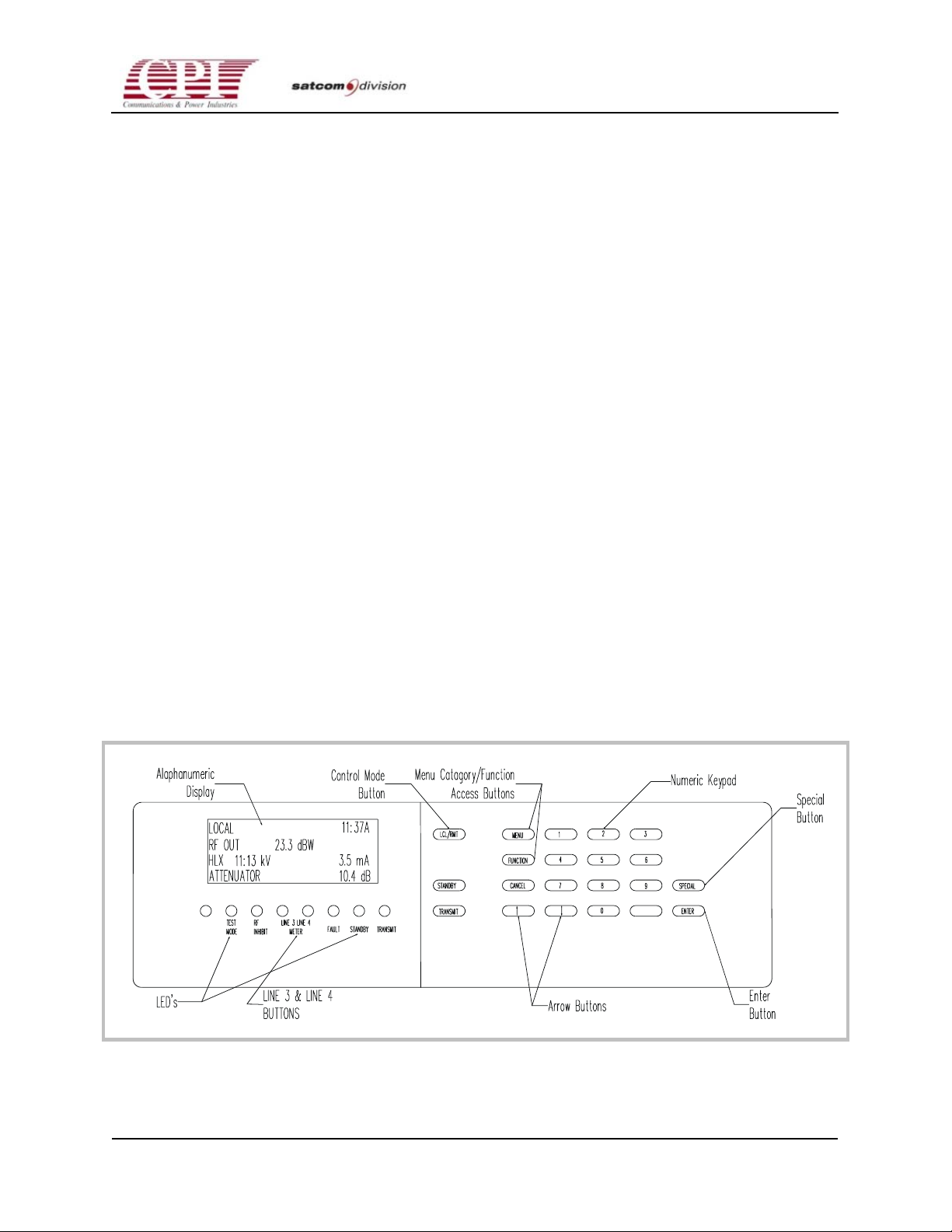
5-1
CHPA SERIES
Chapter 5 Operation
5.1 Overview
The CHPA features a microprocessor control system that accepts control input and provides
CHPA status and meters. This chapter describes CHPA operation via a control panel; details on
control content are in Chapter 8, Appendix B. For CHPA operation via the Computer Interface
port, see Chapter 3, “Interfaces.”
The control panel, as shown in Figure 5-1, accepts input via the pushbutton keypad and
provides CHPA status and meters on the alphanumeric display and associated LEDs.
Individual pushbuttons control essential CHPA functions, such as transmitting and selecting
the Control mode. The keypad and alphanumeric display form a simple terminal through
which the user accesses CHPA features, which are grouped in menu categories, such as RF
Control, Fault Log, and Time/Date Setting.
This chapter consists of the following parts: “Essential CHPA Operating Procedures” provides
step-by-step instructions for essential CHPA operation. “Basic CHPA Operation” describes each
CHPA operating state, CHPA Control mode, and RF Control mode. Sample control panel
screens are included. “Special CHPA Functions” describes the menu category system, which
contains most CHPA features. This chapter concludes with “Quick Access Codes.”
Figure 5-1. Control Panel
OC.01023245 REV.K
D
THIS DOCUMENT IS THE PROPERTY OF COMMUNICATIONS & POWER INDUSTRIES.
REPRODUCTION OR RELEASE WITHOUT EXPRESS PERMISSION IS STRICTLY PROHIBITED
5-1
Page 68
CHPA SERIES
5.2 Essential CHPA Operating Procedures
5.2.1 Transmit
The CHPA’s sole purpose is to amplify a microwave signal. This procedure describes how to
turn on the CHPA, place it in Transmit, and set the RF output. Thoroughly read this procedure
before performing it.
Note: Before starting the CHPA for the first time, be sure that initial poweron and checkout procedures have been performed. See Chapter 4, “Initial
Power-On and Checkout,” for instructions.
1. Switch on the Main Power Breaker.
Note: It is recommended that AC power be kept off for at least one minute
before turning back on.
2. Verify the following:
• No fault message is displayed after the Power-On Self-Test (POST).
• Heater Time Delay counts down from 3:00 to 0:00 minutes. (The Heater Time Delay
countdown will be greater than three minutes if User Heater Time Delay is greater than
zero seconds. User Heater Time Delay can be used to prevent multiple amplifiers from
entering Transmit simultaneously after a prime power failure, for example. See
Appendix B under “Time/Date Set” for more information on User Heater Time Delay
setting.)
• STANDBY is reported on Line 2 of the display, and no faults have been reported.
3. To avoid a high RF output power when the beam is turned on, set the attenuator to its
maximum setting. To do this.
a. Press the MENU button once. Line 3 should display RF CONTROL.
b. Press the FUNCTION Button until Line 4 displays SET ATTN.
c. Type in 25.0, then press ENTER.
d. Press the Line 3 button to return to the default meter display.
4. Press the TRANSMIT button. Line 2 will first display BEAM ON SEQUENCE for
approximately one second, then will display the RF output power.
5. Apply RF input; do not exceed -10 dBm.
5-2
THIS DOCUMENT IS THE PROPERTY OF COMMUNICATIONS & POWER INDUSTRIES.
REPRODUCTION OR RELEASE WITHOUT EXPRESS PERMISSION IS STRICTLY PROHIBITED
DOC.01023245 REV.K
Page 69

CHPA SERIES
6. Set RF output to the desired level. To do so
a. Press the MENU button once.
b. Enter the desired power level in the units displayed. (To change the units used to report
RF readings and settings, toggle the FUNCTION button until RF DISPLAY appears on
Line 4. Press either arrow key to select the desired RF units. Toggle the FUNCTION
button to return to the SET RF OUT entry on Line 4.)
c. Press ENTER.
d. Press either the Line 3 or Line 4 button to return to the default meter display.
5.3 Normal Shutoff
When transmission is completed and no other activity is planned for an hour or so, the CHPA’s
AC power should be switched off to conserve electricity and prolong TWT life. The following
procedure describes normal shutoff:
1. Press the STANDBY button to place the CHPA in Standby state. Verify that Line 2 of the
display indicates STANDBY.
2. Leave the CHPA in Standby approximately 10 minutes to allow the TWT collector to cool
off.
3. Switch off the Main circuit breaker.
Note: Repeated cycling of AC power (more than 3 times per minute or 8
times per minute or 8 times per 5 minute period) will result in excessive
inrush current and may trip circuit breaker.
5.4 Basic CHPA Operation
Basic CHPA operation, which requires little interaction with the CHPA, includes features that
are directly available via front panel buttons: user-chosen CHPA states, Control modes, and RF
modes. Refer to Table B-1 in Appendix B for button definitions. Most CHPA features require a
more sophisticated user interface; these features are described in “Special CHPA Functions”
later in this chapter.
OC.01023245 REV.K
D
THIS DOCUMENT IS THE PROPERTY OF COMMUNICATIONS & POWER INDUSTRIES.
REPRODUCTION OR RELEASE WITHOUT EXPRESS PERMISSION IS STRICTLY PROHIBITED
5-3
Page 70

CHPA SERIES
5.5 CHPA States and Description
The operation of the CHPA may be divided into several states and sequences. They are as
follows:
• POST (Power-On Self-Test)—Initial power on.
• HTD (Heater Time Delay)—Beam-off state while cathode heats to operating temperature.
• Standby—Normal beam-off state.
• BONS (Beam On Sequence)—Transition from Standby (beam off) to Transmit (beam on).
• Transmit—Beam on state (in this state, the CHPA may transmit).
• BOFS (Beam-Off Sequence)—Transition from Transmit to any beam off state.
• Fault (Non-latched)—Beam-off malfunction state; the CHPA will recycle to the state prior to
the fault.
• Fault (Latched)—Beam off malfunction state. Only user intervention will return the CHPA
to a normal operating state.
5.6 Initialization and Power-On Self-Test (POST)
State
To start the CHPA, turn on the Main Power circuit breaker. The microprocessor controller will
perform self-tests and CHPA tests. Once these tests are completed successfully, the user will
have control over the CHPA.
After prime power is applied to the unit, the control panel displays the following:
C P I S A T C O M
6 0 0 / 7 0 0 C H P A
P O W E R O N S E L F T E S T
Once communication with the CHPA controller is established, the control panel displays the
following:
5-4
THIS DOCUMENT IS THE PROPERTY OF COMMUNICATIONS & POWER INDUSTRIES.
REPRODUCTION OR RELEASE WITHOUT EXPRESS PERMISSION IS STRICTLY PROHIBITED
DOC.01023245 REV.K
Page 71

CHPA SERIES
C P I S A T C O M
6 0 0 / 7 0 0 C H P A
P O W E R O N S E L F T E S T
T E S T I N G
While the POST screen is displayed, all self-tests are performed.
If the front panel fails to establish communications with the controller, the panel will report a
communications failure.
POST failure is reported as follows:
C P I S A T C O M
6 0 0 / 7 0 0 C H P A
P O S T F A U L T T E S T # 1
A / D C A L I B R A T I O N
During POST the microprocessor controller performs tests that check the integrity of the
microprocessor controller hardware, software, and CHPA subsystems. Each test is assigned a
number for troubleshooting purposes. In the event of a POST Fault, the fault will be indicated.
(See Appendix B Table B-13.) At the successful completion of the POST, the CHPA will
automatically enter the HTD state.
5.7 Heater Time Delay (HTD) State
Following the POST, if no fault was detected, the unit will automatically enter HTD.
The display shows these features: Local mode, time in 12-hour format, Heater Time Delay
countdown, Beam On (XMIT) selected upon conclusion of HTD, and default meters.
L O C A L 5 : 3 0 P
H T D 2 : 3 9 X M I T S E L E C T
H L X 0 . 0 0 K V 0 . 0 m A
A T T E N U A T O R 1 0 . 0 d B
OC.01023245 REV.K
D
THIS DOCUMENT IS THE PROPERTY OF COMMUNICATIONS & POWER INDUSTRIES.
REPRODUCTION OR RELEASE WITHOUT EXPRESS PERMISSION IS STRICTLY PROHIBITED
5-5
Page 72

CHPA SERIES
In the tube during the Transmit state (Beam On), a beam of electrons is accelerated from an
electron cloud around the cathode, past the anode, through the helix structure, and finally
coming to rest in the collector structure. To create the cloud of free electrons, the cathode is
heated by the heater. Ideally, the cathode should be maintained at a specific temperature.
Cathode temperature is difficult to measure; however, there is a relationship between heater
time after prime power on and cathode temperature. HTD, therefore, is of variable length
(based on prime power off time) to provide optimum cathode temperature in minimum time
after power is applied to the CHPA.
HTD proportional time delay: If time off ≤5 seconds, no HTD.
If 5 seconds <time off<1.5 minutes,
HTD 1.5 x time off + existing HTD
If time off ≥1.5 minutes,
HTD = 3 minutes
During HTD, the user may press the TRANSMIT button to select Beam On when HTD has
elapsed; this action is displayed on the front panel as XMIT SELECT. The user may also press
the MENU button to scroll through available menu categories. See later in this chapter under
“Special CHPA Functions” for a description of the menu category hierarchy. See Appendix B
for a complete description of all menu categories.
5.8 Standby State
Once HTD has elapsed and Beam On has not been selected, the unit will be in the Standby state.
After one minute of Standby, the heater voltage is reduced by approximately 10% to extend
tube life.
The display shows these features: Local mode, time in 12-hour format, Standby, and default
meters.
L O C A L 9 : 4 5 A
S T A N D B Y
H L X 0 . 0 0 K V 0 . 0 m A
A T T E N U A T O R 1 0 . 0 d B
The user now has complete control over the CHPA. Press the TRANSMIT button to move
through the Beam On Sequence to the Transmit state. Press the MENU button to scroll through
a list of CHPA features (described in “Quick Access Codes” later in this chapter and in
Appendix B). To facilitate access to menu categories, use the Quick Access Codes described later
in this chapter.
5-6
THIS DOCUMENT IS THE PROPERTY OF COMMUNICATIONS & POWER INDUSTRIES.
REPRODUCTION OR RELEASE WITHOUT EXPRESS PERMISSION IS STRICTLY PROHIBITED
DOC.01023245 REV.K
Page 73

CHPA SERIES
5.9 Transmit State
If the user pushes the TRANSMIT button, the unit will go through the Beam On Sequence to the
Transmit state. The CHPA will be in the Beam On Sequence for approximately two seconds
before reaching the Transmit state.
The display shows these features: Local mode, Automatic RF Level Control (ALC), time in 12hour format, Beam On Sequence, and default meters.
L O C A L A L C 1 0 : 0 7 A
B E A M O N S E Q U E N C E
H L X 0 . 0 0 K V 0 . 0 m A
A T T E N U A T O R 1 0 . 0 d B
At the successful completion of the Beam On Sequence, the following example screen will be
displayed. The display shows these features: Local mode, Automatic RF Level Control (ALC),
time in 12-hour format, RF output power in dBW, default meters.
L O C A L A L C 1 0 : 0 7 A
R F O U T 2 3 . 0 d B W
H L X 1 2 . 0 1 K V 0 . 0 m A
A T T E N U A T O R 1 0 . 0 d B
The Beam Off Sequence (BOFS) is the transition from any Transmit state to any Beam Off state.
It occurs so quickly that the message for this sequence may not be seen.
5.10 Fault State
The CHPA features Auto Fault Recycle mode; this feature allows the unit to return to a normal
operating state after a transient fault. When a fault occurs, the unit enters the Fault state. After a
brief interval, the unit tries to return to the previous state. If three faults occur within a 20second period, the unit latches in the Fault state. Once the unit is latched in the Fault state, clear
the fault source and then press the CANCEL button to return to the Standby state.
If fewer than 3 faults occur within 20 sec, the unit recycles to the previous operating state. The
RECYCLED FAULT LED will continue to flash when the unit sucessfully recycles from a fault.
Press CANCEL to stop this LED from flashing.
OC.01023245 REV.K
D
THIS DOCUMENT IS THE PROPERTY OF COMMUNICATIONS & POWER INDUSTRIES.
REPRODUCTION OR RELEASE WITHOUT EXPRESS PERMISSION IS STRICTLY PROHIBITED
5-7
Page 74

CHPA SERIES
While in the Fault state, the display will flash and the beeper will sound once every second. The
current fault(s) is/are displayed on Line 2; press either arrow key to cycle through these faults.
To view faults that occur during the Auto Fault Recycle mode, look at the Fault Log (see
Appendix B for a full description). The following screen shows the unit after it is latched in the
Fault state.
L O C A L A L C 4 : 3 7 A
H I G H R E F L R F F A U L T
H L X 0 . 0 0 K V 0 . 0 m A
A T T E N U A T O R 1 0 . 0 d B
5.11 CHPA Control Modes and Hierarchy
The CHPA may be controlled from five points:
• RF Switch port
• Interlock interface
• Local—All control occurs on the front panel.
• Remote—All control occurs on the Serial Remote.
• Computer—All control and monitoring occur on the remote computer.
The RF Switch port and Interlock interface connect to switching systems and user-defined
interlocks. The RF Switch port and Interlock interface have the highest level of control. They are
active at all times; all commands that are issued by the user through these ports must be
acknowledged and acted upon if the CHPA may physically do so.
For the Local, Remote, and Computer modes: On the front panel, press the LCL/RMT button to
toggle through all of the valid control modes (Local, Remote, CIF). If the CHPA is in the Remote
mode, the Serial Remote port may toggle control between the Remote panel (RMT) and the
Computer interface (CIF).
• All control points will always provide status. Commands that modify either the CHPA’s
operating state or RF output will be accepted only from the valid control point.
• The front panel button labeled LCL/RMT will toggle between all control points. The front
panel is the “super user” and may transfer the control point at any time.
• If the control point is transferred to the Serial Remote port or the CIF, the Serial Remote port
may transfer control between itself and the CIF.
• No control transfer may be commanded via the CIF port.
5-8
THIS DOCUMENT IS THE PROPERTY OF COMMUNICATIONS & POWER INDUSTRIES.
REPRODUCTION OR RELEASE WITHOUT EXPRESS PERMISSION IS STRICTLY PROHIBITED
DOC.01023245 REV.K
Page 75
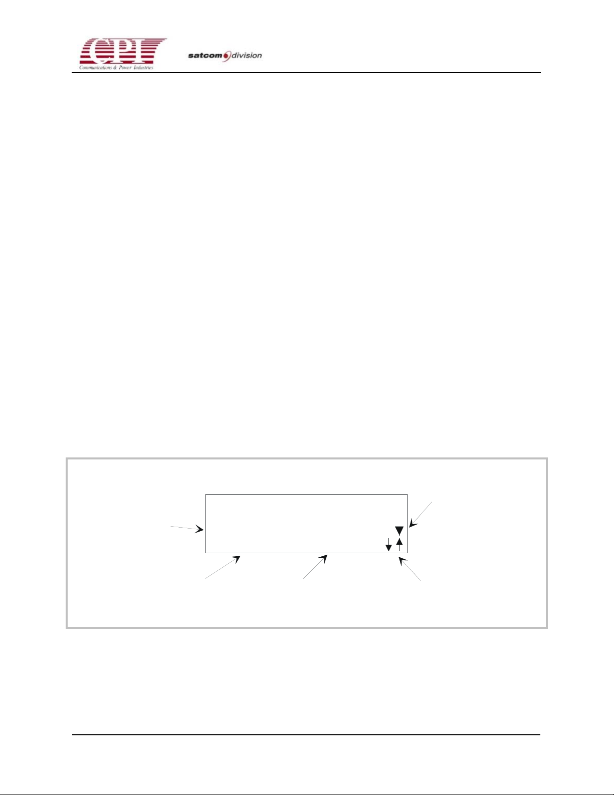
CHPA SERIES
5.12 RF Control Modes
The CHPA features two RF Control modes:
• ALC (Automatic Level Control) mode (ALC is displayed on Line 1)
• Open Loop mode (nothing special is displayed)
Either mode may be selected under the RF Control category. Press the MENU button until Line
3 displays RF CONTROL; press the FUNCTION button until Line 3 displays RF MODE (see the
next subsection, “Special CHPA Functions,” for access to menu categories and Appendix B for a
detailed listing of all menu categories).
In ALC mode, the microprocessor controller adjusts the attenuator to maintain the RF output
power meter reading within ±0.1 dB of the RF output power setting (within the adjustment
limits of the attenuator and RF output limits of the CHPA). During Standby, the CHPA remains
in ALC mode, but the Attenuator Setting is frozen. If ALC is chosen while the unit is in
Standby, the attenuator will be set to maximum attenuation.
While in ALC mode, if the RF Output Power drops below 10 watts (W), the Attenuator Setting
is frozen until the RF Output Power exceeds 10 watts, or a new RF output power request is
made by the user. The CHPA will remain in ALC mode. This feature prevents the attenuator
from being adjusted to 0 dB if RF is removed from the unit.
If the user directly sets the attenuator during ALC mode, the CHPA will revert to Open Loop
RF Control mode.
In Open Loop mode, the microprocessor controller adjusts the attenuator to meet a requested
RF output power setting. Once that setting is attained (±0.1 dB), the Attenuator Setting is fixed
until the next Attenuator Setting or RF output power request is made by the user.
When this triangular
symbol appears, press
the FUNCTION button
to scroll through the
available Functions.
Catagory Title
Press the MENU button
to toggle through available
catagories.
Function Title Entry
LOCAL 11: 0 0P
ND
STA
CIF
IO
BY
CONF I GURAT
N
BAUD RATE : 960 0
When these arrows are displayed,
use the arrow keys to toggle through
the available entries.
Figure 5-2. Example: Accessing CHPA Features
OC.01023245 REV.K
D
THIS DOCUMENT IS THE PROPERTY OF COMMUNICATIONS & POWER INDUSTRIES.
REPRODUCTION OR RELEASE WITHOUT EXPRESS PERMISSION IS STRICTLY PROHIBITED
5-9
Page 76

CHPA SERIES
5.13 Special CHPA Functions
The user may request basic features such as CHPA states and Control modes directly using
front panel buttons. Most CHPA features, however, require a more sophisticated user interface.
To provide logical access to this information, these special CHPA features are grouped into
menu categories.
5.13.1 Factory Authorized Access Mode
Two levels of category access are available:
• User Authorized (limited write/limited read)
• Factory Authorized (unlimited write/read)
Factory Authorized access is granted upon the entry of a security code (FAAC—Factory
Authorized Access Code). This feature prevents users from setting or using special features that
could cause damage to CHPA if misused. These settings and features are included to facilitate
manufacturing and servicing.
5.14 Terminology
Various CHPA features, settings, and controls are grouped according to the following
hierarchy:
Category—Top-level group
Function—Data entry or data display selection within a category
Entry—Data entry or data review within a function
Access to the hierarchy is as follows:
Category—Press the MENU button to toggle through the accessible categories. Category names
appear on Line 3.
Function—When the t symbol appears next to a category, press the FUNCTION button to
toggle through the accessible functions (viewed on Line 4) under that category.
Entry—When the symbols appear next to a function, press either the up or down arrow
keys to toggle through valid entries.
Category—Computer Interface Parameters
Function—Baud Rate (Pressing the FUNCTION button would toggle through other
available entries such as Parity, Print ASCII, and so on.)
5-10
Entry—9600 (Pressing either arrow key will cycle through the other potential entries:
4800, 2400, 1200, 600, 300.)
THIS DOCUMENT IS THE PROPERTY OF COMMUNICATIONS & POWER INDUSTRIES.
REPRODUCTION OR RELEASE WITHOUT EXPRESS PERMISSION IS STRICTLY PROHIBITED
DOC.01023245 REV.K
Page 77
CHPA SERIES
5.15 Exiting A Menu
The user may return from any category to the selected meter display by pressing the buttons on
either Line 3 or Line 4.
5.16 Data Entry Rules
Numerical data will not take effect until the user has pressed the ENTER button. Arrow key
data entry will update when the arrow keys are pressed. The Quick Access Codes are the only
exceptions to these rules.
Numerical entries will indicate their present value until the user enters a new value.
Starting from the meter display on Lines 3 and 4, categories are accessible in the order specified
in Table 5-1, starting with RF Control. Press the MENU button to scroll through the available
categories. While in any menu category, press either the Line 3 or Line 4 buttons to return to the
selected meter displays. Appendix B describes each category in detail.
Table 5-1. Front Panel Categories
Category Name Purpose
RF Control RF Output Setting
Attenuator Setting
RF Power Mode
RF Inhibit
RF Display (W, dBW, dBm)
Suppress Peak Mode (disables RF peak mode
metering)
Linearizer Control (optional) Gain
Phase
Amplitude
RF Trip Limits/Switch Port Relay Settings High RF Alarm
High RF Fault
Low RF Alarm
Low RF Fault
High Reflected RF Fault
Low RF Relay Preference
Fault Relay Preference
Fault Log
Factory Authorized Access Code
OC.01023245 REV.K
D
THIS DOCUMENT IS THE PROPERTY OF COMMUNICATIONS & POWER INDUSTRIES.
REPRODUCTION OR RELEASE WITHOUT EXPRESS PERMISSION IS STRICTLY PROHIBITED
5-11
Page 78
CHPA SERIES
Table 5-1. Front Panel Categories (continued)
Category Name Purpose
Fault Trip Setting* Helix Over Voltage Fault
Helix Under Voltage Fault
Helix Avg Over Current Fault
Helix Voltage Detected in Standby
Factory Tests*
Reset Elapsed Time Meters* Reset Heater Elapsed Time Meter
Reset Beam On Elapsed Meter
Reset to Factory Defaults*
HVPS Test Mode**
User Tests Lamp Test
Beeper Mute
Aux Serial Port Loopback
Time/Date Set User Set Heater Time Delay
12/24 Hour Format
Hour:Minute
Set Month
Date
Year
US Daylight Savings
Remote Interface Parameters Mode (If RMTPNL is displayed, the other selections
under this menu will not be available.)
Device Address
Baud
Parity
Protocol
Check Byte Type
CR Enable
LF Enable
Accept Bad Check Byte
Loopback Test
Installation Test
5-12
THIS DOCUMENT IS THE PROPERTY OF COMMUNICATIONS & POWER INDUSTRIES.
REPRODUCTION OR RELEASE WITHOUT EXPRESS PERMISSION IS STRICTLY PROHIBITED
DOC.01023245 REV.K
Page 79
Table 5-1. Front Panel Categories (continued)
Category Name Purpose
Computer Interface (CIF) Parameters Device Address
Baud
Parity
Protocol
Check Byte Type
CR Enable
LF Enable
Accept Bad Check Byte
Loopback Test
Installation Test
Controller Software Version
Elapsed Hours Beam On Elapsed Time Meter
Heater Elapsed Time Meter
CHPA SERIES
Flash Programming Access Code
Table 5-1 Note:
* Only available once the Factory Authorized Access Code has been entered.
** Only available during FAAM and when unit is in Standby
See appendix B for a complete list of Quick Access Codes.
5.17 Quick Access Codes
Quick Access Codes (QAC) provide access to various CHPA features. If a QAC is used to access
a menu category or a specific function under a menu category, that item will display as if the
MENU and FUNCTION buttons had been used to assess that category or entry. Entering an
invalid QAC will leave the user at the Quick Access Query.
Two levels of read/write data access exist:
• User Authorized Quick Access Codes (UA QAC): Allows selected read and selected write
(codes 00-49) of data.
• Factory Authorized Quick Access Codes (FA QAC): Allows unlimited read and write of all
data. To enter this “super user” mode, a special access code (Factory Authorized Access
Code) must be entered; see Appendix B.
OC.01023245 REV.K
D
THIS DOCUMENT IS THE PROPERTY OF COMMUNICATIONS & POWER INDUSTRIES.
REPRODUCTION OR RELEASE WITHOUT EXPRESS PERMISSION IS STRICTLY PROHIBITED
5-13
Page 80

CHPA SERIES
To use the Quick Access Codes:
1. Press the SPECIAL button.
2. Use the numerical keypad to enter the desired two-digit QAC; pressing ENTER will not be
necessary as it is for other numerical entries.
L O C A L A L C 1 1 : 1 7 A
R F O U T 0 . 0 W
Q U I C K A C C E S S C O D E
The following lists correlates UA QACs and FA QACs with menu categories and functions.
User Authorized Quick Access Codes (00-49)
00 RF Output Setting
01 Attenuator Setting
02 RF Power Mode
03 RF Inhibit
04 Suppress Peak Mode
05 Not used
06 Linearizer Control (if installed)
07 High RF Alarm
08 High RF Fault
09 Low RF Alarm
10 Low RF Fault
11 High Reflected RF Fault
12 Low RF Relay Preference
13 Fault Relay Preference
14 Fault Log
15 Factory Authorized Access Code
16 Lamp Test
17 Time/Date Set
18 Remote Interface Parameters
19 CIF Parameters
5-14
THIS DOCUMENT IS THE PROPERTY OF COMMUNICATIONS & POWER INDUSTRIES.
REPRODUCTION OR RELEASE WITHOUT EXPRESS PERMISSION IS STRICTLY PROHIBITED
DOC.01023245 REV.K
Page 81

CHPA SERIES
20 Controller Software Version
21 Heater Elapsed Time Meter
22 Beam On Elapsed Time Meter
Factory Authorized Quick Access Codes (50-99) are only accessible once the Factory Authorized
Access Code (FAAC) has been entered. See previous description of the FAAC.
50 Helix Over Voltage Fault
51 Helix Under Voltage Fault
52 Helix Average Over Current Fault
53 Helix Voltage Detected in Standby
54 CHPA HVPS Test Mode
55 Reset Heater Elapsed Time Meter
56 Reset Beam On Elapsed Time Meter
OC.01023245 REV.K
D
THIS DOCUMENT IS THE PROPERTY OF COMMUNICATIONS & POWER INDUSTRIES.
REPRODUCTION OR RELEASE WITHOUT EXPRESS PERMISSION IS STRICTLY PROHIBITED
5-15
Page 82

CHPA SERIES
This page is intentionally left blank.
5-16
THIS DOCUMENT IS THE PROPERTY OF COMMUNICATIONS & POWER INDUSTRIES.
REPRODUCTION OR RELEASE WITHOUT EXPRESS PERMISSION IS STRICTLY PROHIBITED
DOC.01023245 REV.K
Page 83
6-1
CHPA SERIES
Chapter 6
Maintenance
6.1 Overview
This chapter provides instructions for routine maintenance of the compact high power
Traveling Wave Tube Amplifier (CHPA) and performance testing. It covers procedures and test
equipment for scheduled maintenance tasks, electrical calibration, and performance testing. It
also explains how to diagnose and repair common problems to the circuit-card assembly level
(PCB).
Note: Improper maintenance of the CHPA may void the warranty. For
details, see Appendix D, “Warranty and Support Information.”
WARNING! THE PERSON PERFORMING MAINTENANCE OF THIS EQUIPMENT
MUST HAVE TRAINING AND KNOWLEDGE OF BOTH THE PRODUCT AND SAFETY
REQUIREMENTS AND SAFETY ISSUES RELATED TO THE EQUIPEMENT. READ
AND PRACTICE THE SAFETY GUIDELINES IN CHAPTER S AT THE FRONT OF
THIS MANUAL.
WARNING! IN SOME CASES IT MAY BE REQUIRED TO WORK ON THE
EQUIPMENT WITH EXPOSED LIVE VOLTAGES EXCEEDING 50 V. ACCESS INTO
THE CHPA AND WORKING CIRCUITRY WITH LIVE VOLTAGES EXCEEDING 50 V IS
RESTRICTED TO AUTHORIZED PERSONNEL SKILLED IN RF AMPLIFIERS AND
HIGH-VOLTAGE EQUIPMENT. THE PERSON EXPOSED TO LIVE VOLTAGES MUST
BE OBSERVED BY AT LEAST ONE OTHER PERSON ABLE TO SWITCH OFF THE
VOLTAGE WITHOUT DELAY. ALSO, THE OBSERVER SHOULD BE TRAINED TO
RENDER FIRST AID BY MEANS OF CARDIOPULMONARY RESUSCITATION (CPR).
THE OBSERVER MUST HAVE IMMEDIATE ACCESS TO THE MAIN CIRCUIT
BREAKER “EMERGENCY OFF” BUTTON. WORK SAFELY!
6.2 Scheduled Preventive Maintenance
To function safely and effectively, the CHPA requires periodic maintenance. This consists of
inspecting, cleaning, testing, and calibrating the HPA’s subsystems at one- to six-month
intervals. In addition, a daily log should be kept of all the CHPA meter readings, including
heater and beam hours of operation and any other trends. This can be helpful in identifying
emerging or continuing problems.
OC.01023245 REV.K
D
THIS DOCUMENT IS THE PROPERTY OF COMMUNICATIONS & POWER INDUSTRIES.
REPRODUCTION OR RELEASE WITHOUT EXPRESS PERMISSION IS STRICTLY PROHIBITED
6-1
Page 84
CHPA SERIES
Preventive maintenance is divided into mechanical maintenance, electrical calibration, and
performance testing. Also provided is a description of how to care for spare TWTs and start-up
procedures to follow when the HPA is turned off for extended periods. The recommended
maintenance schedule is shown in Table 6-1. Certain test equipment is required for these
maintenance procedures. Table 6-2 lists the recommended equipment; equipment with
equivalent accuracy or capacity may be substituted. Locations of major assemblies are shown in
drawing 01020260, “Compact HPA power supply and 01020371 /01020270/01022070 RF
assembly drawings.”
6.3 Mechanical Preventive Maintenance
WARNING! BEFORE ATTEMPTING ANY INSPECTION OR CLEANING, SWITCH OFF
ALL POWER AND LEAVE UNIT FOR FIVE MINUTES BEFORE PERFORMING
SERVICE OPERATIONS). WHEN USING SOLVENTS, PROVIDE ADEQUATE
VENTILATION AND AVOID BREATHING FUMES. WHEN CLEANING WITH AIR,
WEAR SAFETY GOGGLES AND USE CLEAN, DRY, COMPRESSED AIR NOT
EXCEEDING 25 PSI (1.75 KG/CM).
Table 6-1. Preventive Maintenance Schedule CHPA
Mechanical Task Daily 1 Month 3 Months 6 Months 1 Year
1 Log Meter Readings X
2 Clean Air Filter X1
3 Check LEDs and Display X1
4 Perform Visual Inspection X1
5 Collector Air System Maintenance1 X
6 Check the Collector Blower X2
7 Perform Misc. Cleaning X1
Electrical Task Daily 1 Month 3 Months 6 Months 1 Year
1 Perform Initial Power-On Check X
2 Test/Verify Fault & Alarm Circuits and
X
Limit Settings
3A Verify Heater Setting X
3B Verify Collector Setting X
3C Verify Helix Setting and Metering1 X
4 Verify RF Metering1 X
6-2
THIS DOCUMENT IS THE PROPERTY OF COMMUNICATIONS & POWER INDUSTRIES.
REPRODUCTION OR RELEASE WITHOUT EXPRESS PERMISSION IS STRICTLY PROHIBITED
1
DOC.01023245 REV.K
Page 85
CHPA SERIES
Table 6-1. Preventive Maintenance Schedule CHPA (continued)
Electrical Task Daily 1 Month 3 Months 6 Months 1 Year
5 Run Performance Tests X
6 Test Any Spare Tubes X
Table 6-1 Notes:
1. Cleaning may be required more or less frequently than shown.
2. Blower replacement at 40,000 hours of operation.
Table 6-2. Recommended Test and Service Equipment Description
(Listed equipment below may be substituted by any equivalent piece of test equipment.)
Sweep Signal Generator, frequency range HP 8360, 8350 DC to 20 GHz, capable of CW and sweep
operation, compatible with Scalar Analyzer, item.
RF Power Meter complete with power HP 437B, 438A with 8481A Power Head sensors, Type N, 50
Ohms, power measurement range -30 to +20 dBm.
Variable Attenuator 0 to 25 dB, DC to 20 GHz, Merrimac ASM25-11K 50 Ohms.
Scalar Network Analyzers, frequency range HP 8757 with two sensors DC to 20 GHz, complete with dual
detector probes. Should have dual markers, with Delete mode. Compatible with Sweep Signal Generator
(item 1).
RF Splitter, precision 2-way, 50 Ohms, Type N, HP 11667A DC to >20 GHz.
High quality, low loss RF test cables as required for test set up.
Microwave Frequency Counter, 3.DC to 20 GHz.* HP 5340A
*Required only if Sweep Generator is not digitally controlled or phase locked.
Clip-On mA Meter HP 428B Clip-On DC Millimeter 1 mA to 10 A +/- 3%.
Voltmeter-Fluke 8050 DVM 4-digit and Triplett Multimeter.
Couplers Input and Output Coaxial, and Waveguide.
Calibrated Waveguide Coupler Narda, HP, with others. Directional Coupler. Coupling factor 40 dB,
directivity 30 dB.
Dummy Load, 3 kW, Waveline, Narda, etc.
HV Breakout Box, CPI part number 01020673. Adapter Cable Set, part numbers 01020681,01020682.
0– to 60–V, 3-A DC power supply.
Power supply dummy plug, part number 01000474-02 .
OC.01023245 REV.K
D
THIS DOCUMENT IS THE PROPERTY OF COMMUNICATIONS & POWER INDUSTRIES.
REPRODUCTION OR RELEASE WITHOUT EXPRESS PERMISSION IS STRICTLY PROHIBITED
6-3
Page 86
CHPA SERIES
Table 6-2. Recommended Test and Service Equipment Description (continued)
Digital Thermometer, Fluke or equivalent.
Basic Tool Kit Time Motion tools.
Crystal Detector HP 8470B—2.
Radiation Detector Narda 8611 meter with 8621 probe.
Fixed RF Attenuator Set (3, 6, 10, 20 dB) H11581A.
Oscilloscope 100 MHz, 2 channel, 5 MV sensitivity.
OPTIONAL TEST EQUIPMENT
Spectrum Analyzer, DC to 20 GHz HP 8561E, 8563E, frequency range, 50-ohm input. 8595E, 8566B.
6.4 Visual Inspection
At one-month intervals, the CHPA should be inspected visually for physical defects. If the
equipment is subjected to severe environmental conditions, inspections should be performed
more frequently. The daily equipment readings log is a good source for clues that indicate
intermittent or marginal conditions. Any increase in reflected power or unexplained fault
conditions could point to a deteriorating condition that may be found during a thorough visual
inspection. The main circuit breaker must be off while the following general inspection is
performed.
1. With the main circuit breaker off, check that all connector plugs are properly seated in their
mating connectors and have not been damaged. Replace any bad connector plugs and reset
any that are dislodged.
2. Inspect electrical wiring for signs of discolored, broken, or bad insulation. Repair or replace
as needed.
3. Inspect all soldered connections for signs of corrosion, cracking, or dirt. Clean and resolder
as needed.
4. Look for signs of dirt or moisture contamination, which can cause short-circuiting, arcing,
corrosion, or overheating. Clean contaminated areas with a lint-free cloth, a small vacuum
cleaner, or a compressed-air blower at low pressure. Beware of electrostatic discharge (ESD)
when using compressed air. See “Protecting Parts from Electrostatic Discharge”, later in this
chapter.
5. Inspect all waveguides for discoloration, cracks, loose connectors, and improper sealing.
Tighten or replace waveguides as required.
6-4
THIS DOCUMENT IS THE PROPERTY OF COMMUNICATIONS & POWER INDUSTRIES.
REPRODUCTION OR RELEASE WITHOUT EXPRESS PERMISSION IS STRICTLY PROHIBITED
DOC.01023245 REV.K
Page 87

CHPA SERIES
6. With AC power disconnected at its source, retighten the main power line terminal (TB1)
with an insulated screwdriver. The gradual failure of this terminal is indicated by a decrease
of contact pressure caused by thermal expansion and contraction.
7. Check for other defects. These include, but are not limited to, wear, breakage, deterioration,
fungus, excess moisture, and mounting integrity.
6.4.1 Inspecting and Cleaning Air Filters
The air filter at the rear intake of the amplifier should be checked bimonthly and cleaned or
replaced as follows:
1. Inspect the filters for dirt. If necessary, clean with hot water and mild detergent. Dry
thoroughly.
2. Replace the filter.
6.4.2 Checking A3 LEDs and Display
At least once a month, run the CHPA’s built-in test to verify proper operation of all indicators.
To run this test, press the Menu key repeatedly until LAMP TEST appears in the display. Press
Enter.
6.4.3 Collector Air System Maintenance
The TWT collector airflow system must be checked to ensure that it is properly transferring the
heat into the airstream and away from the TWT. This means that the measurement of air flow
and temperature and the inspection and elimination of any contaminants restricting the air flow
must be performed periodically. The recommended cycle is three months, but inspection may
be required more often if local air pollution warrants it.
Follow these steps to verify the cooling:
1. Put the CHPA in Standby and allow the TWT to cool before switching off the main circuit
breaker on the HPA front panel. Switch off the main breaker. The control panel display
should be dark.
2. Inspect the exhaust screen and collector radiator for blockage with a flashlight. All collector
radiator fins should be free of material. If not, remove the TWT and the cover on the
collector to blow out the material. Clean the air exhaust screen as required.
3. If the radiator is clean, power up the amplifier.
4. Put the amplifier in Transmit and check the collector air temperature rise by measuring the
intake air temperature and the exhaust air temperature. After 5 minutes of operation, the
exhaust air temperature rise should be no more than 65
and Troubleshooting” chapter of the CHPA Service Manual.
o
C. If not, refer to the “Maintenance
OC.01023245 REV.K
D
THIS DOCUMENT IS THE PROPERTY OF COMMUNICATIONS & POWER INDUSTRIES.
REPRODUCTION OR RELEASE WITHOUT EXPRESS PERMISSION IS STRICTLY PROHIBITED
6-5
Page 88

CHPA SERIES
6.4.4 Checking B1 Collector Blower
The collector blower is a rotating component subject to wear. Inspect it every six months.
Follow these steps to check operation of the collector blower:
1. With the CHPA in Standby state, open the top cover.
2. Listen for whining, rattling, or other unusual noises from the collector blower that might
indicate worn bearings or other malfunctions. If a mechanical stethoscope is available, listen
for motor-bearing rumble. If such noises are present, replace the blower.
6.4.5 Miscellaneous Cleaning
You must perform the following cleaning procedures on the HPA every three months or more
frequently in unusually dirty environments.
• Clean all transformers, inductors, and coils, using a small vacuum cleaner, a compressed-air
blower at low pressure, or a lint-free cloth.
• Clean the front panel using a dry, clean cloth or a soft-bristled brush.
6.5 Electrical Preventive Maintenance
Operating voltages and metering accuracy must be verified every six months. If any voltage is
not within the range stated in the maintenance chapter for the assembly, it should be adjusted;
the daily log for the equipment should note the indication before and after adjustment. In
addition, perform the entire initial power-on and checkout as described in Chapter 4, “Initial
Power-on and Checkout.” The assemblies to be checked and adjusted are A1, A2, A5, A7, and
A9. Also test the safety, fault, and alarm circuits. Refer to the appropriate assembly maintenance
section for adjustment. After performance testing (described later in this chapter), it may be
necessary to replace V1 or V2 if the results are not within specification.
6.6 Spare TWT Maintenance and Periodic
Operation of the Amplifier
The following procedure is recommended for conditioning spare TWTs. It is also applicable for
HPAs that are used only occasionally or are turned off for prolonged periods of time (several
weeks or months). The following list presents the conditions for operating the TWT (ranked
from most to least desirable effects on the life of the TWT).
• Amplifier continuously running in the Beam On state with RF on
• Beam on, RF off during downtime
• Beam and heater off during long downtime
6-6
THIS DOCUMENT IS THE PROPERTY OF COMMUNICATIONS & POWER INDUSTRIES.
REPRODUCTION OR RELEASE WITHOUT EXPRESS PERMISSION IS STRICTLY PROHIBITED
DOC.01023245 REV.K
Page 89
CHPA SERIES
• Heater voltage backed off, beam off during downtime
• Heater voltage full, beam off during downtime If TWT tubes are stored for extended periods
of time, the TWTs should be operated at least every six months using the following
procedure.
Note: Running the TWT at 0.3 V above the heater voltage on the label can
reduce the TWT life by as much as one half.
Note: If the spare TWT is to be tested, follow the instructions in TWT
Replacement. If the spare TWT is to be tested, follow the instructions in
“TWT Replacement” later in this chapter.
1. The amplifier should be turned on with no RF drive applied.
2. Allow the TWT to warm up for at least 5 minutes, but not longer than 15 minutes, before
applying operating voltages.
3. Enter standard operating mode on the HPA control panel.
4. Put the amplifier in Transmit.
5. If the TWT will operate in Transmit without a limit trip, continue this procedure. If not refer
to “Maintenance and Troubleshooting” in the CHPA Service Manual for V2.
6. The TWT should be run without RF until the helix current has stabilized.
7. Apply RF slowly up to the point of rated power.
8. Run with and without RF input for a minimum of 30 minutes after the body current has
stabilized. The time required to stabilize varies with the age of the tube, storage time, and
storage conditions.
9. Follow the instructions in “Performance Testing”.
10. Go through normal shutdown.
Once the TWT is in service, it is important that the tube is operated correctly. There are three
guidelines to follow:
• In Redundant Mode (1:X configuration), the amplifier should be left in Transmit. Leaving
the TWT in Standby with the heater on for several hours can cause the cathode to age more
quickly. This reduces the life of the TWT (even with heater back off) and may create gas that
will poison the cathode and reduce the emission.
• The collector radiator must be kept clean. If the radiator becomes clogged, the collector can
overheat and over a long period can produce gas that can poison the cathode and affect the
performance. Cleaning the external cooling air filters is also important.
• The heater must be operated at the nameplate voltage for the particular TWT. A voltage
setting too high or too low can cause premature failure. However, when the TWT is old and
the beam current drops because of cathode depletion, the heater voltage can be raised 5
percent without causing any harm. See heater adjustment procedures in the CHPA Service
Manual.
OC.01023245 REV.K
D
THIS DOCUMENT IS THE PROPERTY OF COMMUNICATIONS & POWER INDUSTRIES.
REPRODUCTION OR RELEASE WITHOUT EXPRESS PERMISSION IS STRICTLY PROHIBITED
6-7
Page 90

CHPA SERIES
6.7 Performance Testing
At six-month intervals, perform the tests for power and gain, gain response, and radiation
levels, and record their results. If the results are not satisfactory, then you might have to
troubleshoot the RF system and replace assemblies. Refer to this section as required. You will
need the following equipment or equivalents as described in Table 6-1:
• Sweep signal generator
• Frequency counter
• Scalar analyzer
• Power meter
• Power sensor
6.8 Power and Gain
Follow these steps to test the HPA power and gain. Record the results on the chart provided in
Table 6-3.
1. Connect the equipment as shown in Figure 6-1.
2. Set the input drive level to minimum and the HPA gain to maximum.
3. Set the sweeper to CW to the frequencies selected. These will be used every time preventive
maintenance is performed so that a trend can be developed.
4. Increase the drive level until the HPA has reached saturation. Record level on the test data
sheet.
5. Reduce the drive level until HPA is at the rated power output (if the result of step 4 is
greater than the rated power output).
6. Calculate the gain and record the results on the test data sheet. Gain = Po (dBm)–Pi (dBm).
7. Reduce drive level until HPA is at rated power -10 dB. It may be necessary to use a 10 dB
fixed attenuator at the HPA input to achieve a reliable input power measurement.
8. Calculate the gain and record the result on the test data sheet.
9. Repeat for all required frequencies.
6-8
THIS DOCUMENT IS THE PROPERTY OF COMMUNICATIONS & POWER INDUSTRIES.
REPRODUCTION OR RELEASE WITHOUT EXPRESS PERMISSION IS STRICTLY PROHIBITED
DOC.01023245 REV.K
Page 91

TABLE 6-3. CHPA PERFORMANCE TEST RESULTS
DATE ___________________________
CHPA MODEL S/N_______________________
TWT MODEL S/N_______________________
CHPA SERIES
HEATER VOLTAGE
HEATER CURRENT
NOTE 1
____________________V
NOTE 1
____________________A
HELIX VOLTAGE ____________________kV
COLLECTOR 1 VOLTAGE
COLLECTOR 2 VOLTAGE
BEAM CURRENT
NOTE 1
NOTE 1
____________________kV
NOTE 1
____________________kV
____________________A
HELIX CURRENT (NO RF) ____________________mA
NOTE 1
: MEASURED USING OPTIONAL “BREAK-OUT BOX” AVAILABLE FROM CPI.
FREQ POWER OUT—MAXIMUM GAIN
(DO NOT EXCEED RATED) @ RATED/MAX POWER
F1________ ___________________________ _______________________
F2________ ___________________________ _______________________
F3________ ___________________________ _______________________
F4________ ___________________________ _______________________
MIN POWER SPEC _____________dBm
MIN GAIN SPEC _____________dB @ RATED
TESTED BY _________________________
OC.01023245 REV.K
D
THIS DOCUMENT IS THE PROPERTY OF COMMUNICATIONS & POWER INDUSTRIES.
REPRODUCTION OR RELEASE WITHOUT EXPRESS PERMISSION IS STRICTLY PROHIBITED
6-9
Page 92
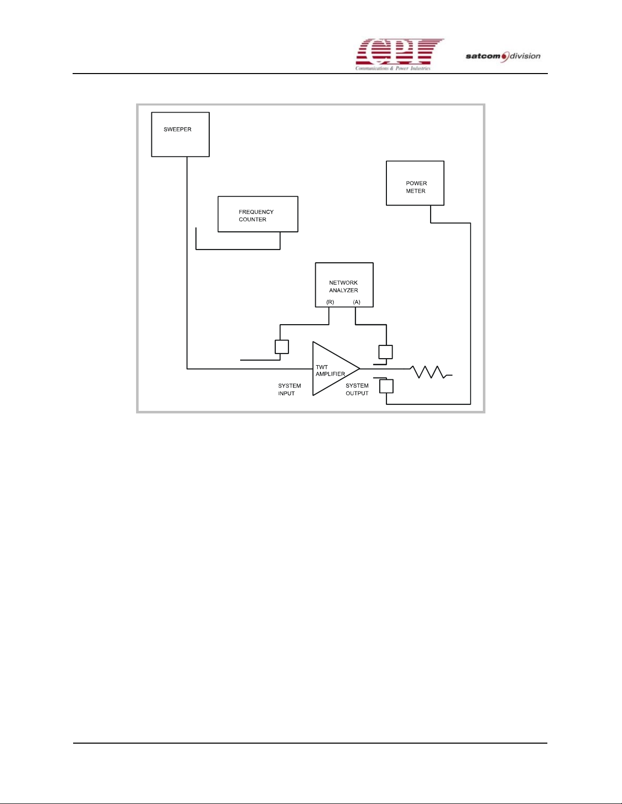
CHPA SERIES
Figure 6-1. TWT Amplifier Test Setup
6-10
THIS DOCUMENT IS THE PROPERTY OF COMMUNICATIONS & POWER INDUSTRIES.
REPRODUCTION OR RELEASE WITHOUT EXPRESS PERMISSION IS STRICTLY PROHIBITED
DOC.01023245 REV.K
Page 93
7-1
CHPA SERIES
Chapter 7
Drawings and Schematics
This chapter contains drawings and schematics for the 600W / 700W /750W Compact High
Power Amplifier (CHPA). Table 7-1 contains a list of drawings and their drawing numbers.
Table 7-1. Compact HPA Drawings
Title Drawing Number
Assy, Power Supply, Compact HPA & LM (500W to 750W) 01020260-XX
Interconnect, CHPA 01020261
Outline, Compact HPA 01020269
RF Assy, Ku-Band, Compact HPA & LM 01020270-XX
Specification, C-Band Compact HPA 01020296
Specification, Ku-Band Compact 700W 01020297
RF Assy, C-Band, Compact HPA & LM 01020370-XX
RF Diagram, CHPA 01020371
Specification, DBS Compact HPA 01022061
RF Assy, DBS-Band, Compact HPA & LM (500W to 750W) 01022070-XX
Assy, Power Supply, 750W Thales Tube Compact HPA & LM 01022071-00
RF Assy, DBS-Band 750W Thales Tube Compact HPA & LM 01022080-00
Outline, DBS-Band 750W Compact HPA 01022081
RF Diagram, DBS-Band 750 01022082
Procedure, LTI Linearizer Tuning 01025031
Specification, Ku-Band 750W Compact HPA 01029516
Note:
Drawings are in numerical order
Paper Manual: Printed drawings follow this page.
CDROM Manual: Drawingfiles are in the “Drawing” folder.
* Refer to the service manual, 01021149, for the respective LMs.
OC.01023245 REV.K
D
THIS DOCUMENT IS THE PROPERTY OF COMMUNICATIONS & POWER INDUSTRIES.
REPRODUCTION OR RELEASE WITHOUT EXPRESS PERMISSION IS STRICTLY PROHIBITED
7-1
Page 94

CHPA SERIES
This page is intentionally left blank.
7-2
THIS DOCUMENT IS THE PROPERTY OF COMMUNICATIONS & POWER INDUSTRIES.
REPRODUCTION OR RELEASE WITHOUT EXPRESS PERMISSION IS STRICTLY PROHIBITED
DOC.01023245 REV.K
Page 95

8-1
Chapter 8
Supplementary Data
Appendix A: Specifications
Appendix B: Control Appearance and Content
Appendix C: Replaceable Parts
Appendix D: Warranty/Support Information
Appendix E: Options and Features
CHPA SERIES
OC.01023245 REV.K
D
THIS DOCUMENT IS THE PROPERTY OF COMMUNICATIONS & POWER INDUSTRIES.
REPRODUCTION OR RELEASE WITHOUT EXPRESS PERMISSION IS STRICTLY PROHIBITED
8-1
Page 96

CHPA SERIES
This page is intentionally left blank.
8-2
THIS DOCUMENT IS THE PROPERTY OF COMMUNICATIONS & POWER INDUSTRIES.
REPRODUCTION OR RELEASE WITHOUT EXPRESS PERMISSION IS STRICTLY PROHIBITED
DOC.01023245 REV.K
Page 97

A-1
Appendix A
Specifications
Chapter 7 includes specifications for all CHPAs listed in this manual.
CHPA SERIES
OC.01023245 REV.K
D
THIS DOCUMENT IS THE PROPERTY OF COMMUNICATIONS & POWER INDUSTRIES.
REPRODUCTION OR RELEASE WITHOUT EXPRESS PERMISSION IS STRICTLY PROHIBITED
A-1
Page 98

CHPA SERIES
This page is intentionally left blank.
A-2
THIS DOCUMENT IS THE PROPERTY OF COMMUNICATIONS & POWER INDUSTRIES.
REPRODUCTION OR RELEASE WITHOUT EXPRESS PERMISSION IS STRICTLY PROHIBITED
DOC.01023245 REV.K
Page 99
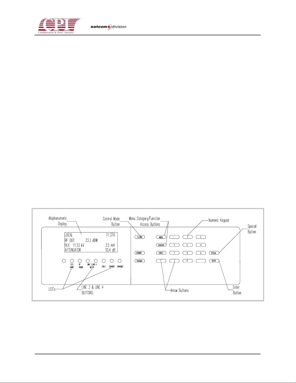
B-1
CHPA SERIES
Appendix B
Control Appearance and Content
B.1 Overview
This chapter lists the function of each control key, indicator, and display item on the HPA. For
operational procedures, see Chapter 5, “Operation,” and Chapter 4, “Initial Power-On and Checkout.”
B.2 Buttons
The front panel displays data using a 4-line by 20-character vacuum fluorescent alphanumeric
display and six LEDs (see Figure B-1). A push-button keypad is used for operating the HPA and
entering data. Numerical data will not be entered until the user has pressed the ENTER button.
Data entry that relies on the arrow keys will be updated when the arrow keys are pressed. The
Quick Access Codes are the only exceptions to these rules
Figure B-1. Front Panel Picture
OC.01023245 REV.K
D
THIS DOCUMENT IS THE PROPERTY OF COMMUNICATIONS & POWER INDUSTRIES.
REPRODUCTION OR RELEASE WITHOUT EXPRESS PERMISSION IS STRICTLY PROHIBITED
B-1
Page 100
CHPA SERIES
Table B-1. Front Panel Button Description
Button Name Button Function
0–9 Press these buttons for numerical data entry.
.(decimal point) Press this button to enter a decimal point. This button is also used in conjunction with
the SPECIAL button when entering Quick Access Codes (see SPECIAL button in this
table).
LCL/RMT Press this button to toggle between the following HPA control points:
LOCAL—Front Panel
REMOTE—Remote Panel
CIF—Computer Interface
STANDBY Press this button to initiate a Standby request.
TRANSMIT Press this button to initiate a Transmit request.
MENU Press this button to scroll through available menu categories.
FUNCTION When the symbol appears next to a menu category, press this button to toggle through
available entries.
CANCEL Press this button to clear fault messages and exit the Fault state once the fault source
has been eliminated. This button is also used to clear the contents of the Fault Log.
Also used to stop the Recycled Fault LED from flashing.
SPECIAL If the symbol appears next to an entry, press this button to scroll through valid entries.
If the symbol appears next to an entry, press this button to scroll through valid entries.
Press this button, then the decimal point button, to enter Quick Access Codes.
ENTER Press this button to enter numerical data (excluding Quick Access Codes).
Line 3 Press this button to scroll display Line 3 through the available meters.
Press this button while in any menu category to return to the current meter display.
Line 4 Press this button to scroll display Line 4 through the available meters.
Press this button while in any menu category to return to the current meter display.
B.3 LEDs
Six LEDs are located below the alphanumeric display and indicate unit states and other
important information. The LEDs appear in Table B-2 in the order they appear on the front
panel from left to right.
B-2
THIS DOCUMENT IS THE PROPERTY OF COMMUNICATIONS & POWER INDUSTRIES.
REPRODUCTION OR RELEASE WITHOUT EXPRESS PERMISSION IS STRICTLY PROHIBITED
DOC.01023245 REV.K
 Loading...