

CPI MCR211A, MCR212A, MCR210A, MCR310A, MCR410A Instruction Manual
...
Instruction Manual
Alpha Remote Series
Multi-Channel Remotes 1/2013
MCR210A
MCR211A
MCR212A
MCR310A
MCR410A
MCR411A
TSR210A
TSR410A
TSR411
TSR412A
TSR(K)100A
Includes -DM versions
CPI Communications 941 Hensley Lane Wylie, Texas 75098
Phone (972)429-7160 (800)869-9128 Fax (972)429-7165 (888) 437-5360 www.cpicomm.com

TABLE OF CONTENTS
SPECIFICATIONS AND COMPATIBILITY
GENERAL INFORMATION
PRE-INSTALLATION CONSIDERATIONS
P
OWER
P
HONE LINE
R
ADIO PROGRAMMING
INSTALLATION
P
HONE LINE
OWER
P
P
ARALLEL OPERATION
SETUP ADJUSTMENTS
LINE BALANCE 2
R
X AUDIO 2
X AUDIO 3
T
SIGNALING 3
DTMF
E
ARPIECE ADJUST 3
OWER UP SYNC 3
P
OPERATION
CONTROLS AND INDICATORS
PROGRAMMING THE ALPHA REMOTE
G
ENERAL PROGRAMMING INFO 4
ROGRAMMING PROCEDURES 4-5
P
LONING 5
C
E
RASING 5
DIP SWITCH SETTINGS AND MISC CONNECTIONS
WARRANTY
PARTS LIST
ADJUSTMENT LOCATIONS
BOARD LAYOUTS AND SCHEMATICS
BASE BOARD COMPONENT LAYOUT 12
ASE BOARD SCHEMATICS 13-17
B
L
INE INTERFACE 13
IC AUDIO 14
M
INE AUDIO, NOTCH FILTERS 15
L
P
OWER SUPPLY, AMP 16
M
ICROPROCESSOR 17
RONT PANEL LOGIC BOARD COMPONENT LAYOUT 18
F
F
RONT PANEL LOGIC BOARD SCHEMATIC 19
F
RONT PANEL SWITCH BOARD COMPONENT LAYOUT 20
RONT PANEL SWITCH BOARD SCHEMATIC 21
F
1
2
2
2
2-3
3
3
4-5
6
7
8-10
11
12-21

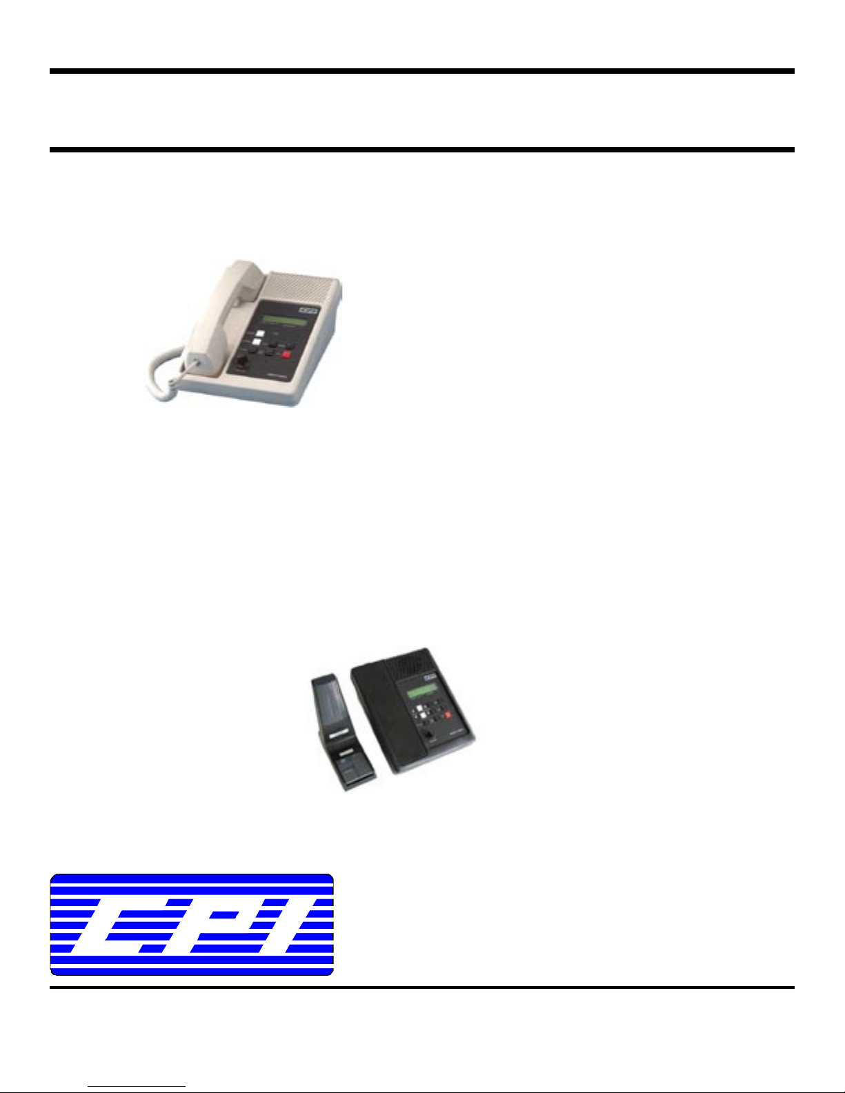
MCR/TSR Alpha Series Remotes
SPECIFICATIONS
Power input 12VAC @ 500mA for wall pack (provided) or 12 to 16VDC @ 500mA.
Indicators LCD Channel/System/Group/Zone display, Transmit LED, Monitor LED, Scan
LED, and Privacy LED. Other indicators vary model.
Controls Channel/System/Group/Zone, PTT, Monitor, Scan, Intercom, and Privacy. Other
controls vary by model.
Line input level -20dBm to +10dBm adjustable.
Line output level -20dBm to +8dBm adjustable.
Phone line impedance 200K ohm on-hook, 600 ohm off-hook.
Receive audio compression Less than 3dBm change in output for 20dBm change in input above threshold.
Audio output to speaker Speaker output is 2 watts with less than 3% distortion at full compression.
Dimensions 5.5” x 9” x 10”
Weight 3.40lbs, with Deskmic option - 3.85lbs
Maximum parallel remotes 50
Connections Phone line: Modular jack
Handset: Four pin modular jack
Deskmic: Six pin modular jack (deskmic option replaces handset)
COMPATIBILITY
Following table lists the Alpha remote and matching termination panel(s) with the compatible radio(s).
Remote Term Panel Radio Local Control
MCR210a MCP200 Motorola Radius M200 9
Maxtrac 300 9
Maxtrac LS (LTR) 9
MCP200G Radius GM300 9
MCP200S Radius SM120 9
MCP200M Radius M1225 (20 channel w/ LCD)
MCP200MLS Radius M1225-LS
MCR211a MCP200C Motorola CDM1550, LS, LS+
MCR212a MCP200CM Motorola CM300
TSR210a TSP200 Motorola Maxtrac 800MHz (B7) 9
Desktrac 800MHz (B7) 9
TSP209 Maxtrac 900MHz (B7) 9
TSR211a TSP200X Motorola GTX
MCR310a MCP300 Midland Syntech XTR 9
MCR410a MCP400 Kenwood TK-630/TK-730/TK-830 9
TSR410a TSP400 Kenwood TK-930/TK-931 9
TSR411a TSP401 Kenwood TK-840/TK-940/TK-941
TSR412a TSP402 Kenwood TK-680/TK-780/TK-980
MCR411a MCP401 Kenwood TK-690/TK-790/TK-890
TSR(K)100a TSP150K Kenwood TK-7150/TK-8150
TSP180K Kenwood TK-7180/TK-8180
TSP710K Kenwood TK-5710/TK5810/TK5910
TSP100NX Kenwood NX-700/NX-800
TSP720K Kenwood TK-5720/TK5820
1

MCR/TSR Alpha Series Remotes
GENERAL INFORMATION
The Alpha series remote control unit, when combined with the appropriate termination panel, provides:
• a reliable means of remotely controlling specific radio models from various manuf actures
• an LCD channel display, channel/system/group/zone controls, scan control with indicator, intercom button,
privacy button with indicator, speaker, volume control, and other functions that vary by model
• a maximum of 50 parallel remote units may be connected to the control station via the termination panel
PRE-INSTALLATION CONSIDERATIONS
Power
The remote is powered from 120V 60Hz AC using the supplied wall pack transformer. In most cases, when the
supplied wall pack is used, a standard grounded outlet is acceptable. An ideal ground point would consist of a ½
inch copper rod driven six feet into the earth with at least a #16 AWG copper wire connecting it to the GND terminal
of the remote, taking the shortest path possible. A 12 to 16VDC source may be used in place of the wall pack.
Phone line
For proper operation, use of a high quality voice grade circuit such as a leased line or in-house twisted pair wiring is
required. DC continuity is not required. Connection is made to the remote via the supplied six foot modular cord.
Radio Programming
See MCP/TSP series termination panel manual and refer to appropriate matching term panel for required radio
programming in order for system to operate correctly.
INSTALLATION
The Alpha series remotes are a specialty remote and require the matchin g termination panel and radio to operate.
DTMF signaling is used to communicate between the remote and term panel. A standard tone remote o r p anel will
not work on the system.
Phone Line
Phone line connections are made using the supplied modular line cord. Only the two center conductor wires (the
red and green) are to be connected and used on a two wire system. Do not connect the black and yellow on a two
wire system. The four center conductor wires (the red, green, black, and yellow) are u sed o n a four wire full duplex
system. They are not polarity sensitive. Alpha remotes are shipped from the factory in the two wire mode. Refer
to “Table 1 - Dip Switch Settings” to configure for four wire full duplex mode.
Power
Power connections consist of plugging the wall pack in the nearest grounded AC receptacle. If DC power is
required, remove the wall pack and connect the positive supply lead to terminal 1 of J3 and the negative supply
lead to terminal 2 of J3.
Parallel operation
Up to 50 Alpha series remote may connected in parallel. As parallel remotes are installed, the set up procedure
need only to be performed on the new remote(s).
SETUP ADJUSTMENTS
Most adjustments can be accessed through the bottom of the remote (see page 11 for pictorial).
Line Balance
Terminate the phone line at the radio end by the appropriate MCP/TSP termination panel. Remove the screws
securing the top half of the housing to access R43. Power up the unit with the handset on-hook and the PTT switch
on the handset pressed or the PTT pressed down on deskmic version. You should now hear a test tone on the
speaker (adjustment of the volume control may be necessary). Adjust R43 until the tone heard is at minimum or
null setting. Line balance is now complete. Lifting the handset off-hook or pressing the monitor on the deskmic will
end the test tone.
Rx Audio
The RX adjustment (R1) has been factory set to function with input levels from -10dBm to +10dBm.
2

MCR/TSR Alpha Series Remotes
Tx Audio
The TX adjustment (R44) has been factory set to provide 0dBm level to the phone line. Minor TX adjustments may
need to be performed due to variances in each system and personal preferences.
DTMF Signaling
The DTMF signaling (R98) has been factory set to provide optimal level for functions to operate. The DTMF
signaling adjustment should only be adjusted, when functions are not operating correctly, to compensate for lines
and/or audio interference. Note: turning level to max position will render system inoperable.
Earpiece Adjust
The earpiece level (R87) is preset to midrange and may need adjusted to a comfortable listening level.
Power Up Sync
When power is applied to the unit, cycle the handset off hook and back on hook or press and release the desk mic
monitor button to “sync” the system.
OPERATION
Most remote functions operate the same as the radio. Any radio function that requires a sustained depression of a
button is not supported. All parallel remote displays and/or indicators update simultaneously. Individual but tons
and indicators are used to provide straight forward operation.
CONTROLS AND INDICATORS
Channel/System/Group/Zone Display: The LCD gives a real time indication as to what
channel/system/group/zone the radio is on.
Scan Indicator: When the scan mode is activated by pressing the scan button on the remote, the scan LED will
illuminate and the LCD will display “SCANNING”. Note: Some radios do not support the scan LED or “SCANNING”.
Monitor Indicator: Operates the same as the radio when used.
Transmit Indicator: Illuminates when any remote keys or when the local microphone, plugged into the MCP/TSP
termination panel, has been keyed with a supported system that allows the radio to be used as a control station.
Privacy Indicator: When the privacy mode is selected by pressin g the privacy button (see below), the privacy LED
will illuminate and the LCD will display “PRIVACY”. All parallel remote privacy LED’s will illuminate.
Channel/System/Group/Zone up: Pushed once, the selected channel/system/group/zone will incre m ent up by
one. If held, it will continue to increment up until released.
Channel/System/Group/Zone down: Pushed once, the selected channel/system/group/zone will increment down
by one. If held, it will continue to increment down until released.
Scan Button: Toggles the radio scan function on/off.
Monitor Button: Toggles the radio monitor function on/off.
PTT Button (front panel): Allows the user too transmit without lifting the handset.
PTT Button (handset): Allows the user to transmit with the handset.
PTT Button (deskmic): Allows the user to transmit with the deskmic (-DM option, replaces handset).
Privacy Button: When pressed, will disable all parallel remotes from being able to transmit or receive.
Note: E2 solder jumper must be installed to activate.
Intercom Button: Provides intercom capability between parallel remotes without keying the radio.
3

MCR/TSR Alpha Series Remotes
PROGRAMMING THE ALPHA SERIES REMOTES
The control panel buttons are utilized for programming alpha-numeric me ssages into the Alpha series remotes to
be displayed on the LCD display. Special software or external devices are not required.
All models contain a fixed character list that is accessed during programming to sele ct alpha-numeric characters.
The characters are as follows:
_0123456789ABCDEFGHIJKLMNOPQRSTUVWXYZ
Scrolling beyond “Z” rolls back to “_”, while scrolling below “_” rolls back to “Z”. The character “_” is represented on
the screen as a blank space.
Programming procedures: (contact CPI Communications for models not listed)
All procedures require the user to power on the remote while pressing a button. Until the button is released, the
remote will display “” in the LCD display.
MCR210a, 310a, 410a, 212a
1) Press and hold the Channel Ï button while turning power on to enter programming mode. When released,
the display will read “ch00” or “Ch01” with its associated message.
2) Using the Channel Ï and Channel Ð buttons, select which channel to enter/edit programming. The channel
number will increment or decrement one digit for each short press and will rapidly increment/decrement when
pressed and held.
3) Press the Monitor button. A solid cursor will appear under the first/next position of the message.
4) Use the Channel Ï and Channel Ð buttons to scroll through the character list. When the desired character
has been reached, press the Monitor button once to store the character and advance to the next position.
Repeat Step 4 to store subsequent characters.
5) When the last character has been stored, press the Scan or P Scan button to store the message.
(Note: In the event of storing a character in the 10
press Scan, continue to Step 6.)
6) Repeat Steps 2, 3, 4 until all desired channels have been programmed with messages.
7) Press the Scan or P Scan button twice to exit programming mode and begin normal operation.
TSR411a, 412a
1) Press and hold the System Ï button while turning power on to enter programming mode. When released, the
display will read “1-1” with its associated message.
2) Using the System Ï, System Ð, Group Ï, and Group Ð buttons, select which system and group to
enter/edit programming. The system/group numbers will increment or decrement one digit for each short
press and will rapidly increment/decrement when pressed and held.
3) Press the Scan button. A solid cursor will appear under the first/next position of the message.
4) Use the System Ï and System Ð buttons to scroll through the character list. When the desired character
has been reached, press the Scan button once to store the character and adva nce to the next position.
Repeat Step 4 to store subsequent characters.
5) When the last character has been stored, press the PTT button to store the message.
(Note: In the event of storing a character in the 9
6) Repeat Steps 2, 3, 4 until all desired systems and groups have been programmed with messages.
7) Press the PTT button twice to exit programming mode and begin normal operation.
MCR411a
1) Press and hold the Group Ï button while turning power on to enter programming mode. When released, the
display will read “1-1” with its associated message.
2) Using the Group Ï, Group Ð, Channel Ï, and Channel Ð buttons, select which group and channel to
enter/edit programming. The group/channel numbers will increment or decrement one digit for each short
press and will rapidly increment/decrement when pressed and held.
3) Press the Scan button. A solid cursor will appear under the first/next position of the message.
th
(MCR210a, 310a, 410a) or 9th (MCR212a) position: do not
th
position: do not press PTT, continue to Step 6.)
4

MCR/TSR Alpha Series Remotes
4) Use the Group Ï and Group Ð buttons to scroll through the character list. When the desired character has
been reached, press the Scan button once to store the character and advance to the next position. Repeat
Step 4 to store subsequent characters.
5) When the last character has been stored, press the PTT button to store the message.
(Note: In the event of storing a character in the 9
6) Repeat Steps 2, 3, 4 until all desired groups and channels have been programmed with messages.
7) Press the PTT button twice to exit programming mode and begin normal operation.
MCR211a, TSR(K)100a
1) Press and hold the Zone Ï button while turning power on to enter programming mode. When relea sed, the
display will read “1-1” with its associated message.
2) Using the Zone Ï, Zone Ð, Channel Ï, and Channel Ð buttons, select which zone and channel to enter/edit
programming. The zone/channel numbers will increment or decrement one digit for each short press and will
rapidly increment/decrement when pressed and held.
3) Press the Scan button. A solid cursor will appear under the first/next position of the message.
4) Use the Zone Ï and Zone Ð buttons to scroll through the character list. When the desired character has
been reached, press the Scan button once to store the character and advance to the next position. Repeat
Step 4 to store subsequent characters.
5) When the last character has been stored, press the PTT button to store the message.
(Note: In the event of storing a character in the 9
continue to Step 6.)
6) Repeat Steps 2, 3, 4 until all desired zone and channels have been programmed with messages.
7) Press the PTT button twice to exit programming mode and begin normal operation.
Cloning - All Models
Once a complete list of messages have been manually entered on a single remote, the message data can be
copied from that remote to any number of remotes connected to it.
1) Connect the other remotes together using the same wiring system that will be used for normal operation with
the exception of the termination panel. The termination panel must be disconnected or switched off.
2) Cloning is initiated by pressing and holding the Channel Ð button (MCR210a, 310a, 410 a, 212a), System Ð
button (TSR411a, 412a), Group Ð button (MCR411a), or Zone Ð button (MCR211a, TSR(K)100a) on the
remote with the programmed information, while turning power on. When the button is released, the display
will read “COPYING”.
3) The data copying process takes from twenty seconds to four minutes, depending upon the size of the
message data being transferred. A typical system will finish copying in less than one minute. When cloning is
finished, the “COPYING” message is replaced with a channel number indication on both the sending and
receiving remotes. All remotes in the system are ready for normal operation once the termination panel is
reconnected or powered on.
4) After all remotes in the system have been programmed, it is recommended to place dip switch 3 in the “ON”
position on all remotes to disable the cloning function being recognized from parallel remotes. This will
prevent accidental erasure of the alpha information.
Erasing - All Models
The entire message EEPROM can be erased in a single operation on individual remotes.
1) Erasing is initiated by pressing and holding the Monitor button (MCR210a, 310a, 410a, 212a) or the Scan
button (TSR411a, 412a, MCR411a, 211a, TSR(K)100a) while turning power on. When the Monitor or Sca n
button is released, the remote will display “ERASING” or “” on some models.
2) Once all information has been erased, the “ERASING” or “” message will be replaced with
“ch00”, “Ch01”, or “1-1”, the message data will be erased, and the remote enters the channel select mode of
programming.
3) Pressing the Scan or P Scan button (MCR210a, 310a, 410a, 212a) or PTT button (TSR411a, 412a,
MCR411a, 211a, TSR(K)100a) two times exits the erasing mode, leaving the message memory erased.
th
position: do not press PTT, continue to Step 6.)
th
(MCR211a) or 8th (TSR(K)100a) position: do not press PTT,
5
 Loading...