

CPI TRML Series Instruction Manual
Instruction Manual
TRML Series
Multi-Line Tone Remote
01/2013
CPI Communications 941 Hensley Lane Wylie, Texas 75098
Phone (972)429-7160 (800)869-9128 Fax (972)429-7165 (888) 437-5360 www.cpicomm.com

TABLE OF CONTENTS
SPECIFICATIONS
GENERAL DESCRIPTION
FRONT PANEL CONTROLS AND INDICATORS
INSTALLATION
OWER
P
HONELINES
P
L
OCAL CONTROL CONTACT CLOSURES
D
ESK MIC
H
EADSET
F
OOTSWITCH
E
XTERNAL SPEAKER
P
ARALLEL OPERATION
Line Impedance
Crossmute
L
EVEL SETTINGS
Microphone Sensitivity
Earpiece Adjust
Rx Audio Line Input
Tx Line Output
Notch Filters
PROGRAMMING
E
NTERING PROGRAMMING
E
NABLING/DISABLING LINE SELECT BUTTONS
E
NABLING/DISABLING SELECT ALL BUTTON
E
XIT PROGRAMMING
OPERATION
ELECTING A LINE
S
S
ELECTING MULTIPLE LINES
S
ELECTING A FREQUENCY
T
RANSMITTING/INITIATING CALLS
I
NTERCOM
R
ECEIVING CALLS
M
UTING A LINE
P
RIVACY
DIP SWITCH AND JUMPER SETTINGS
ISC. DIP SWITCH - BASE BOARD
M
L
INE IMPEDANCE DIP SWITCH - MIDDLE BOARD
P
ARALLEL AUDIO DIP SWITCH - MIDDLE BOARD
L
INE ACTIVITY DIP SWITCH - MIDDLE BOARD
2
WIRE & 4 WIRE / RX AUDIO OPTIONS JUMPERS - MIDDLE BOARD
F
OOTSWITCH PTT JUMPER - MIDDLE BOARD
M
ISC. SOLDER JUMPERS - BASE BOARD
M
ISC. SOLDER JUMPERS - TOP BOARD
4
5
6-7
8
8
8
9
9
9
9
9
10
10
10
10
10-11
11-12
12
13
13
13
13
13
13
14
14
14
14
14
14
15
15
15
16
16
16
16-17
17

A
UDIO CONTROLS
LINE AUDIO - MIDDLE BOARD
M
ISC. AUDIO - BASE BOARD
P
ICTORIALS
BACK VIEW
WARRANTY
SCHEMATICS AND BOARD LAYOUT
UDIO CONTROL LOCATIONS
A
BASE BOARD
M
IDDLE BOARD
T
OP BOARD
20
21-25
26-35
36-39
Parts List
B
ASE BOARD
M
IDDLE BOARD
T
OP BOARD
MISC
40-42
43-44
45-46
17
17
18
19
47

TRML REMOTE CONTROL CONSOLE
SPECIFICATIONS subject to change without notice
Power Requirements 120VAC, 60Hz for wall pack (provided). Fused on circuit board.
Dimensions 9.5” x 4” x 7”
Weight TRML - 4.5lbs, with Deskmic Option - 5.2lbs
Audio Output to Speaker 2 Watts at 3% THD into 8 ohms, using supplied wall pack or
Handset Earpiece Level Adjustable via internal potentiometer
Frequency Response +/- 3dB from 300 to 3000Hz, except at notch frequency. 1000Hz reference.
Hum and Noise 50dB below operating levels
Transmit Notch Filter 2175Hz down 50dB from 1000Hz reference level
Receive Notch Filter 2175Hz down 50dB from 1000Hz reference level
Transmit Audio Compression Less than 3dB increase in output with 30dB increase in input beyond threshold.
Receive Audio Compression Less than 3dB increase in output with 30dB increase in input beyond threshold.
Threshold is adjustable from -24dBm to +15dBm.
Line Impedance 2 wire: 600 ohms or 2.4k ohms, dip switch selectable per line
4 wire: 600 ohms or 10K ohms, dip switch selectable per line
Line Output Level Factory set at 0dBm. Adjustable to +10dBm maximum
Control Tone Frequencies Guard Tone: 2175Hz @ +10dBm for 140ms
Function Tone: F1 1950Hz @ 0dBm for 40ms
F2 1850Hz @ 0dBm for 40ms
F3 1750Hz @ 0dBm for 40ms
F4 1650Hz @ 0dBm for 40ms
F5 1550Hz @ 0dBm for 40ms
F6 1450Hz @ 0dBm for 40ms
F7 1350Hz @ 0dBm for 40ms
F8 1250Hz @ 0dBm for 40ms
Monitor Tone: 2050Hz @ 0dBm for 40ms
Hold Tone: 2175Hz @ -20dBm for duration of PTT
Operating Modes Standard: Two wire simplex per line
Optional: Four wire simplex per line, Four wire duplex per line
Maximum Parallel Remotes 10 remotes per line
Connections Phone lines: 8 pin RJ45 modular jacks - TIA/EIA T568-B
Relay Outputs: 8 pin RJ45 modular jacks - TIA/EIA T568-B
Handset: 4 pin modular jack
Deskmic: 6 pin modular jack
Headset: 6 pin modular jack
Gooseneck: 3 pin plug, screw lock connector
Power: 3 pin EN3® weather tight locking connector
4

TRML REMOTE CONTROL CONSOLE
GENERAL DESCRIPTION
The TRML series multi line tone remote allows users to reliably control up to four separate conventional and/or
trunked two way base stations and/or repeaters via twisted pair wiring. One TRML remote allows users to
communicate on 4 separate radios individually or a combination of 2 to 4 radios simultaneously. Incoming receive
audio signals are controlled by independent select and unselect audio controls with the capability of each line being
muted.
Programmable features include line enable/disable and select all enable/disable. The TRML does not require
additional software for programming. Data is stored in a nonvolatile EEPROM and will retain the data when power
is lost. Programming is accomplished using the standard front panel buttons on the face of the remote allowing
fully field programmability.
When a PTT occurs from the handset, front panel, optional desk mic, optional gooseneck, or optional headset
interface the other mics will mute to eliminate background noise during the transmission. Receive audio i s
transferred to the handset earpiece when taken off hook.
Parallel Status Indication allows the remote to update when a channel change function is performed from another
remote on the system. The TRML activates the Parallel Transmit Indication (PTI) by lighting the TX LED when
parallel remotes key and can also be configured to mute the speaker by enabling the crossmute function to prevent
audio feedback when remotes are in close proximity.
Standard features include volume controls for selected and unselected lines, individual activity line indicators, front
panel PTT switch, LED transmit indicator, monitor function with LED indicator, intercom function with LED indicator,
select all function with indicator, individual receive mute switches with LED indicators, receive and transmit audio
compression, 2175Hz transmit and receive notch filters, PTI indication, crossmute, 2 wire and 4 wire selection per
line, locking quick disconnect power supply, and RJ45 connections to termination panels.
The TRML is available in many optional configurations. Some of the available options include: (-DM) Desk mic in
addition to handset, (-GN) Gooseneck mic replaces the handset, (-FS) Foot switch to activate PTT, (-CC) Contact
Closure PTT relay output, (-8F) Eight frequency control per line, (-SPK/JACK) 3.5mm jack for amplified speaker,
and (-SPKR) Speaker (external, amplified, requires 12VDC).
5

TRML REMOTE CONTROL CONSOLE
FRONT PANEL CONTROLS AND INDICATORS
LINE ACTIVITY
LINE ACTIVITY
TRML
TRML
LINE 1 LINE2
LINE 1 LINE2
RX MUTE
RX MUTE
F1 F2
F1 F2
F5
F5
UNSEL
UNSEL
SEL
SEL
VOLUME
VOLUME
LINE 3
LINE 3
RX MUTE
RX MUTE
F6
F6
(Programming Display)
(Programming Display)
RX MUTE
RX MUTE
F3
F3
F7
F7
TX
TX
LINE 4
LINE 4
RX MUTE
RX MUTE
F4
F4
F8
F8
PRIVACYSELECT ALL
PRIVACYSELECT ALL
INTERCOM
INTERCOM
MONITOR
MONITOR
Figure 1 - Front Panel
Front panel
Figure 1 shows a view of the front panel of the TRML series. The front panel features line activity indicators, line
selection, Rx mute per line, select all line function, intercom and monitor functions, Tx function, and volume controls
for selected and unselected audio. Optional eight channel frequency selection is available on the TRML-8 F. The
programming display and Privacy button are for future applications and/or special applications. All functions and
features include indicators except the volume controls.
Controls and Indicators
LINE ACTIVITY indicators: Orange LED’s located above each LINE button will light indicating Rx audio activity on
that line. The orange activity indicators remain lit while audio is present and for 3 seconds (factory default) after
audio is absent.
LINE1-LINE4 Buttons: Selects one of four lines to be the selected line and is indicated by green a LED. When
one line is selected, the previous selected line is canceled. Only one line can be selected unless Select All is
activated, which then any combination of lines can be selected and/or unselected to be transmitted on.
RX MUTE Button: Mutes and unmutes incoming Rx audio, of the above respective Line button, from being
monitored on the handset or speaker and lights a green LED to indicate the line is muted.
F1-F8 Buttons: Selects frequency and sends correspondi ng function tone on the selected line. When a frequency
is selected, it lights the frequency LED. Selection will remain on last selected frequency until a different frequency
is selected regardless of other remote functions.
6

TRML REMOTE CONTROL CONSOLE
SELECT ALL Button: Allows user to select multiple lines to transmit on. Once the button has been pressed, a
green LED shows the Select All function has been activated and the user can now select an d unselect desired lines
using the LINE1-LINE4 buttons. The last selected line before entering into the Select All mode is still controlled by
the Selected Volume control and the other lines are controlled by the unselected volume control.
PRIVACY Button: Non operational. Reserved for future applications.
INTERCOM Button: When pressed and held, provides intercom capability to other parallel remotes on the selected
line(s) without keying the radio. A yellow LED will light as long as the intercom button is pressed.
MONITOR Button: Sends the monitor tone burst, on the selected line, placing the radio into monitor mode to
disable coded squelch (CTCSS/CDCSS) so the line may be monitored before transmitting. A green LED lights as
long as the monitor button is pressed.
TX Button: When pressed and held, allows the user to key the radio and transmit on selected lines. A red TX LED
lights as long as the button is pressed. The TX LED also lights when any PTT occurs from the TRML and will also
light as a parallel transmit indication (PTI) that parallel remotes on the selected line are currently transmitting.
SEL Volume Control: Adjusts the speaker level of the Selected audio when the remote is set to control volumes
independently or adjusts the speaker level of the summed Selected and Unselected audio when the remote is set
to control both.
UNSEL Volume Control: Adjusts the speaker level of the Unselected audio.
Programming Display: Non operational. Reserved for future applications.
7
TRML REMOTE CONTROL CONSOLE
2345678
2345678
2345678
2345678
INSTALLATION
The TRML series tone remote will operate with any remote system using the EIA standard tone control format.
Power
The remote is powered from 120V 60Hz AC using the supplied wall pack transformer. In most cases, when the
supplied wall pack is used, a standard grounded outlet is acceptable. An ideal ground point would consist of a ½
inch copper rod driven six feet into the earth with at least a #16 AWG copper wire connecting it to the GND terminal
of the remote, taking the shortest path possible.
Phone lines
The TRML is designed to work with a high quality voice grade circuit such as leased lines or in-house twisted pair
wiring for each line used. Circuits and wiring must have no dial tone, talk battery, or signaling. DC continuity is not
required.
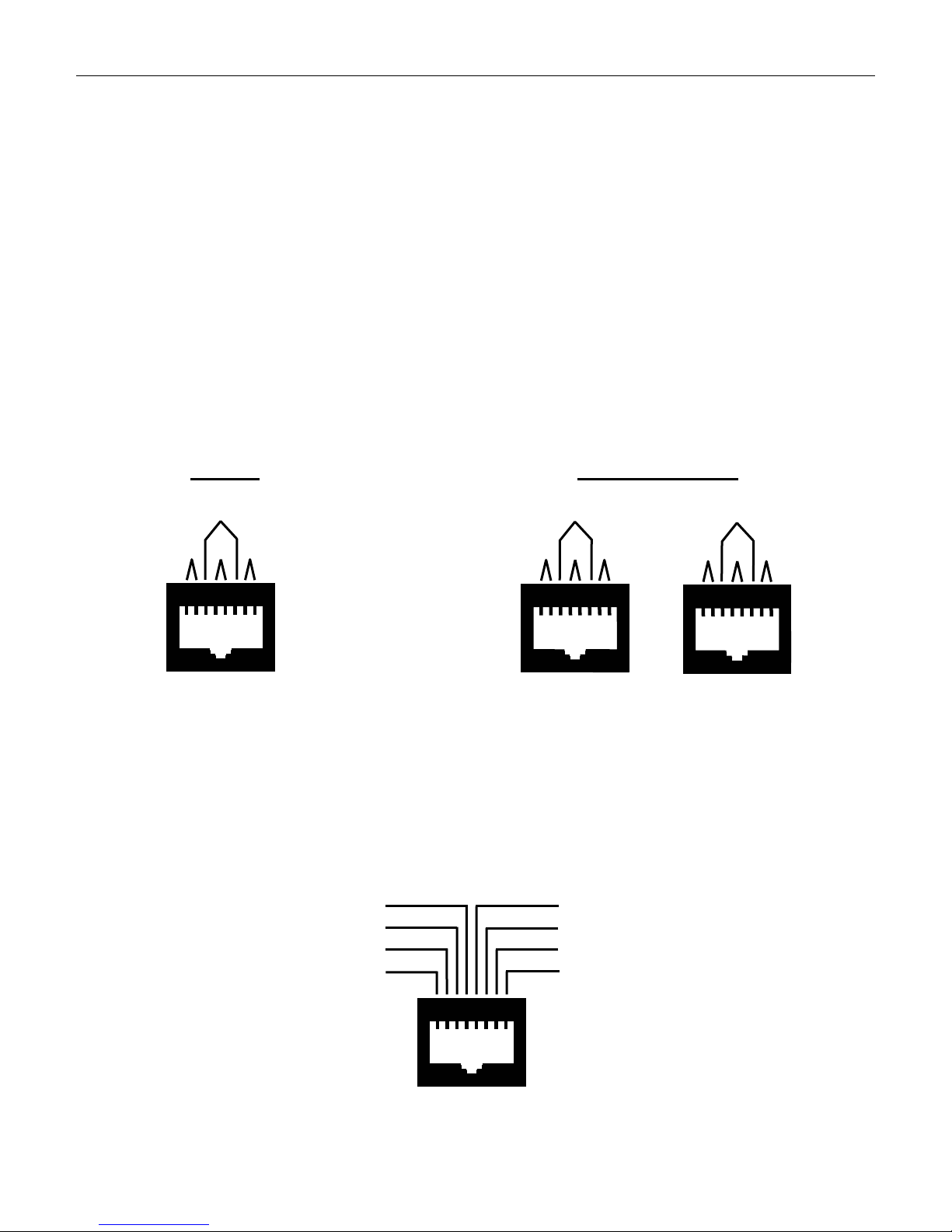
Connections are made to the remote, via the supplied 6 foot modular Cat5/5e/6 cable, to J5 for two wire operation
and to J4 and J5 for four wire operation. J5 provides Tx and Rx connections for two wire lines. J4 provides Tx
connections and J5 provides Rx connections for four wire lines. Figure 2 shows the back views of J5 and J4. The
TRML comes standard with jumper selectable two wire or four wire operation. The TRML is shipped from the
factory in the two wire mode. Refer to Table 3 to configure jumpers for four wire mode.
Two Wire
L3 Tx/Rx
Four Wire/Full Duplex
L3 Rx
L3 Tx
L1
L2 Tx/Rx
Tx/Rx
L4 Tx/Rx
1
J5
L1 RxL2 Rx L4 Rx
1
J5
L2 Tx
L1 Tx
L4 Tx
1
J4
Figure 2 - Phone line Connections
Local Control Contact Closure (-CC option)
The optional local control contact closure provides a normally open dry relay contact closure during PTT on each
individual line. The relay is not activated during intercom. Each relay can be also be configured to close to ground
by installing 2.7 ohm resistors in R180, R179, R178, R177 on the middle board for Lines 1, 2, 3, 4, respecti vely.
Figure 3 shows the back view of J3.
Local 1 -
Local 3 +
Local 2 Local 2 +
Local 1 +
Local 3 Local 4 +
Local 4 -
8
1
J3
Figure 3 - Contact Closure Connection
TRML REMOTE CONTROL CONSOLE
2
345
6
2
345
6
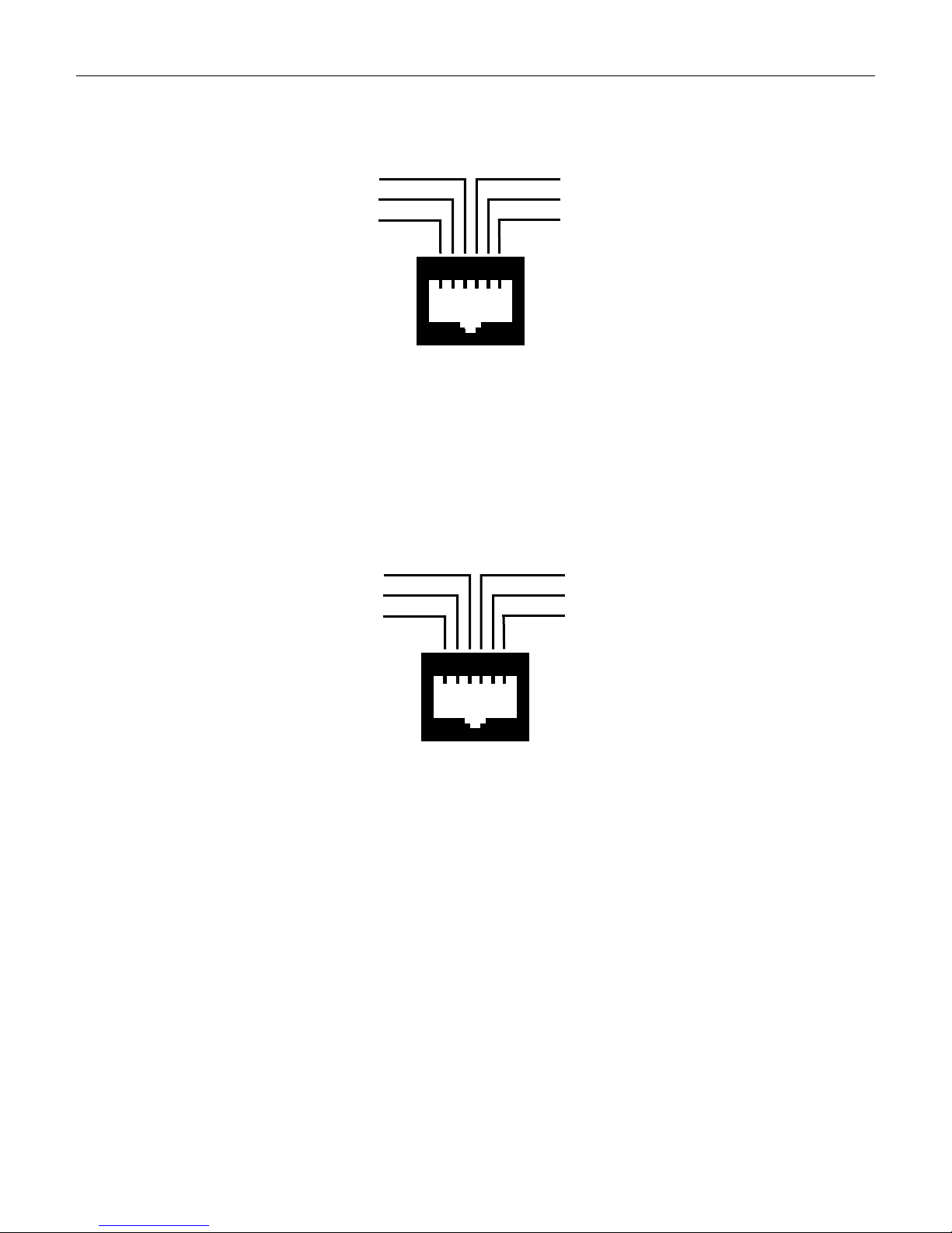
Desk Mic (-DM option)
The optional Desk Mic feature provides connections to accommodate a CPI desk mic for console use. Figure 4
shows the back view of J2.
unused
Ground
Monitor Switch
1
Desk Mic PTT
Desk Mic Hi
Desk Mic Bias
J2
Figure 4 - Desk Mic Connection
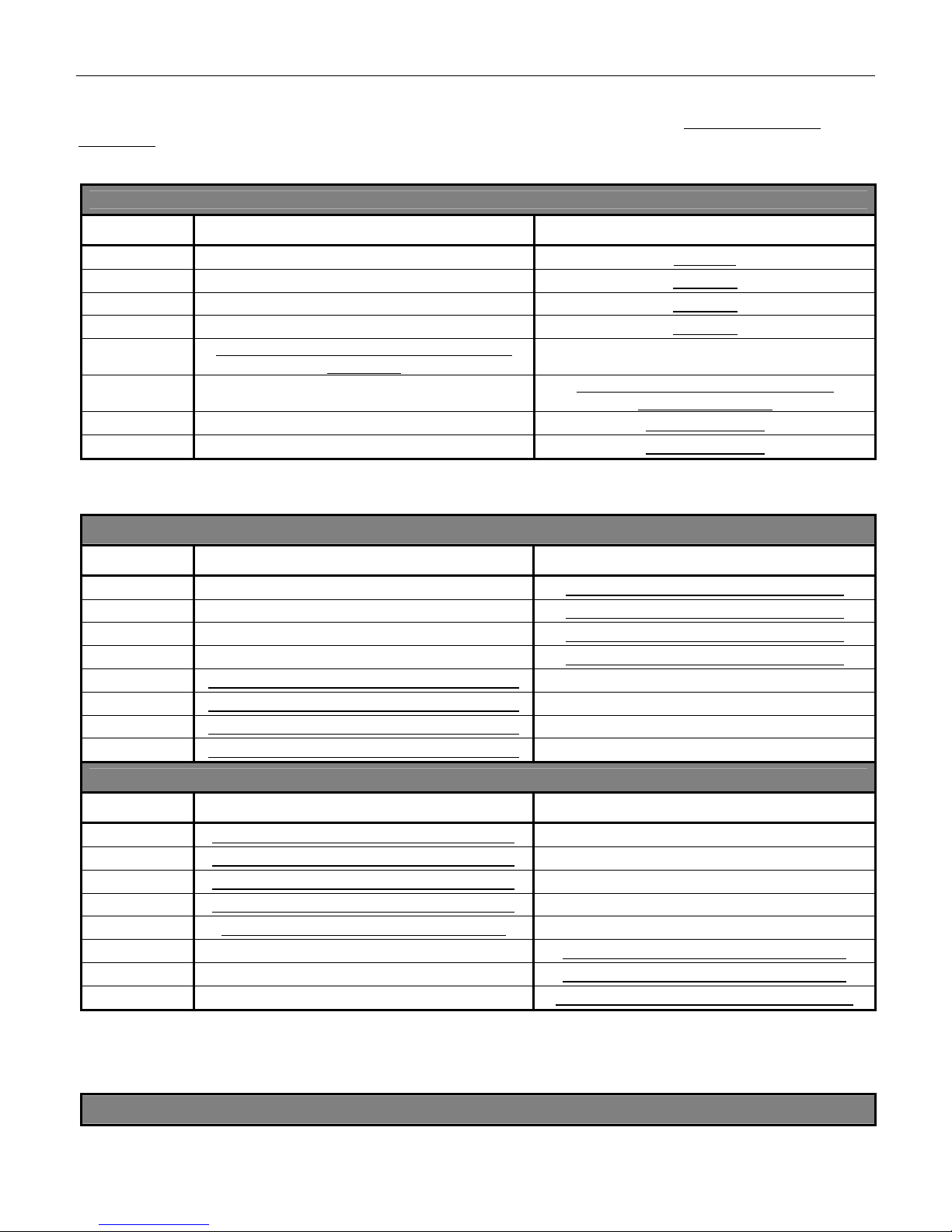
Headset (-HS Box option)
The optional headset input provides availability to directly connect the CPI headset box (sold separately) for hands
free dispatch operation when paired with a compatible headset. Select and/or Unselect audio in the headset
earpiece is determined by jumper selectable configurations (see Table 3 - JU14, JU15). Figure 5 shows the back
view of J1.
Headset Earpiece
Ground
Monitor Switch
1
J1
Headset PTT
Headset Mic Hi
VCC
Figure 5 - Headset Connection
Footswitch (-FS option)
Optional footswitch connection allows the PTT to be activated by the supplied footswitch. Activated PTT is
determined by selectable jumper configuration (see Table 3 - JU13).
Speaker Jack (-SPK/JACK option)
Optional speaker jack provides a 3.5mm jack for connecting the CPI amplified external speaker (sold separately) to
provide a left and right audio effect, for separating audio, which allows easier audio differentiating between the
Select and Unselect calls. Select or Unselect audio can be routed to the external speaker determined by the
selectable jumper configuration (see Table 3 - JU9).
Parallel Operation
Parallel remotes on the same line(s) are an integral part of the remote control system which allows more users and
also allows future expansion of the system. Connecting multiple remotes requires line impedance settings to be
configured for optimal performance of the system.
9

TRML REMOTE CONTROL CONSOLE
ine Impedance
L
When several rem
will decrease to a point where operation is degraded. This occurs when 3 or more remotes are connected in
parallel to the line. Up to ten remotes may be connected in parallel on the same Line. The maximum loss betwee
any remote and termination panel must not exceed 20dB.
T
o compensate for this effect, the TRML remote provides dip switch selectable line impedance setting s. Two wire
operation provides 600 ohm or 2.4K ohm impedance. Four wire operation provides 600 ohm or 2.4K ohm
impedance on the Tx pair and 600 ohm or 10K ohm impedance on the Rx pair. Line impedance settings ar
configured via the S1 and S2 dip switch packages located on the middle board (see Table 2 - S1, S2).
In
parallel remote installations using the same phone line for two wire operation, dip switch S1-5 sh ould be in the
OFF position (2.4K ohms) in all remotes except the last one in the chain on Line 1, S1-6 shou l d be in the OFF
position for Line 2, S1-7 should be in the OFF position for Line 3, S1-8 should be in the OFF position for Line 4.
In
parallel remote installation using the same phone line for four wire operation, dip switch S1 -1 should be in the
OFF position (10K ohms) in all remotes except the last one in the chain on Line 1, S1-2 should be in the OFF
position for Line 2, S1-3 should be in the OFF position for Line 3, S1-4 should be in the OFF position for Line 4
the Rx pairs. Dip switch S1-5 should be in the OFF position (2.4K ohms) in all remotes except the last one in the
chain on Line 1, S1-6 should be in the OFF position for Line 2, S1-7 should be in the OFF position for Line 3, S1-8
should be in the OFF position for Line 4 for the Tx pairs.
C
rossmute
The crossmu
feedback. Crossmute is ideal when multiple remotes are installed in close proximity that audio feedback occurs on
parallel remote speakers. No additional wires between remotes are needed to activate the crossmute feature. The
crossmute feature works by decoding the PTT control tones when parallel remotes key and mutes the speaker
cutting off the audio path to feedback through. Intercom has no effect and will be heard on parallel remotes.
he crossmute feature is enabled when shipped from the factory. Configuring the crossmute feature is dip switch
T
selectable with dip switch 6 located on the bottom of the unit (Table 1 - S1-6). “On” enables crossmute, “Off”
disables crossmute. Note: speaker becomes active all the time regardless of the handset in the off hook posit
when crossmute is disabled.
evel Settings
L
Typical level sett
screwdriver to remove the screws securing the top half of the housi ng to access most of the adjustments. So
adjustments can be accessed from the bottom of the remote.
he following adjustments assume the termination panel has been properly installed and the phone line meets
T
above requirements.
icrophone Sensitivity
M
R75 controls the micropho
control. The potentiometer has been factory set to provide adequate compression for normal voice audio with a
relatively quiet background noise level. Adjustment is located on the bottom baseboard and is also accessible fro
the bottom of the remote. Note: adjustment will affect transmit audio on all lines.
arpiece Adjust
E
R96 controls the R
earpiece level for most environments. Adjustment is located on the bottom baseboard and is also accessib le fr
the bottom of the remote. Note: adjustment will affect receive audio over the earpiece of all lines.
x Audio Line Input
R
The receive line input a
threshold of compression to be adjusted from -24dBm to +15dBm. Separate compression amplifiers and
adjustments are used for each line.
ote control units are connected in parallel on one line, the total system impedance for that line
n
e
for
te feature allows the remote to mute the speaker during PTT from a parallel remote to prevent audio
ion
ings require only a small flathead screwdriver for adjustments and a standard phillips head
me
ne audio level into the transmit compression circuits and therefore acts as a sensitivity
m
x audio into the earpiece. The potentiometer has been factory set to provide a comfortable
om
djusts the audio level to the input of the compression amplifier circuitry. This allows the
10

TRML REMOTE CONTROL CONSOLE
While applying an RF signal modulated with 1000Hz tone at 60% system deviation to the base station receiver,
adjust the termination panel line output for 0dBm to the phone line. Adjust all remotes and each line used as
follows:
Note: Adjustments and measurements are located and taken on the middle board.
Line 1:
a. Apply RF signal as described above.
b. Conne ct a scope or a nalog AC volt meter to ground and U10 pin 1.
c. With R154 fully counter-clockwise, adjust in a clockwise direction until the AC voltage level on scope
(approx. 1Vpp) or meter (approx. 370mVrms) just stops increasing. This point is the threshold of
compression for Line 1.
d. Remove the RF sig nal from the base station and proceed to the next line input adjustment.
Line 2:
a. Apply RF signal as described above.
b. Conne ct a scope or a nalog AC volt meter to ground and U10 pin 8.
c. With R159 fully counter-clockwise, adjust in a clockwise direction until the AC voltage level on scope
(approx. 1Vpp) or meter (approx. 370mVrms) just stops increasing. This point is the threshold of
compression for Line 2.
d. Remove the RF sig nal from the base station and proceed to the next line input adjustment.
Line 3:
a. Apply RF signal as described above.
b. Conne ct a scope or a nalog AC volt meter to ground and U19 pin 1.
c. With R174 fully counter-clockwise, adjust in a clockwise direction until the AC voltage level on scope
(approx. 1Vpp) or meter (approx. 370mVrms) just stops increasing. This point is the threshold of
compression for Line 3.
d. Remove the RF sig nal from the base station and proceed to the next line input adjustment.
Line 4:
a. Apply RF signal as described above.
b. Conne ct a scope or a nalog AC volt meter to ground and U19 pin 8.
c. With R155 fully counter-clockwise, adjust in a clockwise direction until the AC voltage level on scope
(approx. 1Vpp) or meter (approx. 370mVrms) just stops increasing. This point is the threshold of
compression for Line 4.
d. Remove the RF signal from the base station.
Tx Line Output
This level is preset at the factory for 0dBm out to the phone line and may not require readjustment at installation. If
needed, the procedure for each line used is as follows:
Note: Adjustments are located on the middle board and baseboard of the TRML and measurements are taken at
the termination panel which may require two people to perform the procedure.
Line 1:
a. With the handset off-h ook, if applicable, press the intercom button (the handset PTT can be used but
audio may be passed over the air) and adjust the Line 1 Tx audio pot (R125) while saying and holding
the word “Five” into the handset until 0dBm is measured across the phone line at the termination panel.
b. Turn “on” dip switch 7 (located on bottom of unit) and key the remote to lock up the 1950Hz function
tone. Adjust R80 tone level (located on baseboard, underneath middle board) until the 1950Hz
function tone measures 0dBm across the phone line at the termination panel.
c. Return dip switch 7 to the “off” position and proceed to the next line output adjustment.
Line 2:
a. With the handset off-h ook, if applicable, press the intercom button (the handset PTT can be used but
audio may be passed over the air) and adjust the Line 2 Tx audio pot (R142) while saying and holding
the word “Five” into the handset until 0dBm is measured across the phone line at the termination panel.
b. Turn “on” dip switch 7 (located on bottom of unit) and key the remote to lock up the 1950Hz function
tone. Adjust R80 tone level (located on baseboard, underneath middle board) until the 1950Hz
function tone measures 0dBm across the phone line at the termination panel.
c. Return dip switch 7 to the “off” position and proceed to the next line output adjustment.
11

TRML REMOTE CONTROL CONSOLE
Line 3:
a. With the handset off-h ook, if applicable, press the intercom button (the handset PTT can be used but
audio may be passed over the air) and adjust the Line 3 Tx audio pot (R104) while saying and holding
the word “Five” into the handset until 0dBm is measured across the phone line at the termination panel.
b. Turn “on” dip switch 7 (located on bottom of unit) and key the remote to lock up the 1950Hz function
tone. Adjust R80 tone level (located on baseboard, underneath middle board) until the 1950Hz
function tone measures 0dBm across the phone line at the termination panel.
c. Return dip switch 7 to the “off” position and proceed to the next line output adjustment.
Line 4:
a. With the handset off-h ook, if applicable, press the intercom button (the handset PTT can be used but
audio may be passed over the air) and adjust the Line 4 Tx audio pot (R85) while saying and holding
the word “Five” into the handset until 0dBm is measured across the phone line at the termination panel.
b. Turn “on” dip switch 7 (located on bottom of unit) and key the remote to lock up the 1950Hz function
tone. Adjust R80 tone level (located on baseboard, underneath middle board) until the 1950Hz
function tone measures 0dBm across the phone line at the termination panel.
c. Return dip switch 7 to the “off” position and proceed to the next line output adjustment.
Tx Notch Filter
The Tx 2175Hz notch filter is tuned at the factory and should not be readjusted. In the event that the notch filter
needs to be adjusted, the procedure follows:
Note: Adjustment and measurements are made on the baseboard.
a. Apply 0dBm, 2.2Vpp, 2175Hz signal on the Line 1 red and green phone line input.
b. Using a test clip, jumper left side of R6 to left side of R61.
c. With the scope in the single channel mode, connect probe to U8 pin 7. Adjust R52 to obtain a minimum
signal level. Adjust R54 to further reduce the signal level. Recheck R52 then R54 for the smallest
minimum signal level achievable.
Selected Rx Notch Filter
The selected Rx 2175Hz notch filter is tuned at the factory and should not be readjusted. In the event that the
notch filter needs to be adjusted, the procedure follows:
Note: Adjustments and measurements are made on the baseboard with Line 1 selected
a. Apply 0dBm, 2.2Vpp, 2175Hz signal on the Line 1 red and green phone line input.
b. Using a du al channel scope in the X-Y mode, connect one probe to U2 pin 14 and the other probe to U3
pin 8.
c. Adjust R39 until the lissajous pattern closes to a flat line. Remove probes.
d. With the scope in the singl e channel mode, connect probe to U3 pin 14. Adjust R38 to obtain a minimum
signal level. Readjust R39 slightly to further reduce the signal level. Recheck R38 then R39 for the
smallest minimum signal level achievable.
Unselected Rx Notch Filter
The unselected Rx 2175Hz notch filter is tuned at the factory and should not be readjusted. In the event that the
notch filter needs to be adjusted, the procedure follows:
Note: Adjustments and measurements are made on the middle board wit h Line 2 selected
a. Apply 0dBm, 2.2Vpp, 2175Hz signal on the Line 1 red and green phone line input.
b. Using a du al channel scope in the X-Y mode, connect one probe to U3 pin 1 and other probe to U8 pin 8.
c. Adjust R55 until the lissajous pattern closes to a flat line. Remove probes.
d. With the scope in the singl e channel mode, connect probe to U8 pin 14. Adjust R73 to obtain a minimum
signal level. Readjust R55 slightly to further reduce the signal level. Recheck R73 then R55 for the
smallest minimum signal level achievable.
.
.
12

TRML REMOTE CONTROL CONSOLE
PROGRAMMING
Programmable features include line enable/disable and select all enable/disable. The TRML does not require
additional software for programming. Programming is accomplished using the standard fron t panel buttons on the
face of the remote allowing field programmability.
TRML’s are shipped from the factory with all Lines and Select All buttons activated.
To enter the programming mode:
1. Remove power.
2. Press and hold
3. Once the LINE ACTIVITY indicators flash momentary in sequence and any of the green Line Select LED’s
repeatedly flash on/off, release the TX button.
4. The TX LED will repeatedly flash on/off indicating the programming mode is activated.
Enabling/Disabling Line Select Buttons:
Note: Line is enabled when the green LED next to the button is “on”. Line is disabled when green LED is “off”.
1. Enter the programming mode.
2. Select or deselect the lines that are to be enabled or disabled indicated by the LED’s.
3. Exit programming or move to next programming parameter.
Enabling/Disabling Select All Button:
Note: Select All is enabled when green LED next to button is “on”. Select All is disabled when green LED is “off”.
1. Enter the programming mode.
2. Select or deselect the Select All to enable or disabled indicated by the LED.
3. Exit programming or move to next programming parameter.
To exit the programming mode:
1. Press the front panel TX button one time.
2. Unit is now in normal operation with most recent programming parameters programmed.
the front panel TX button while reapplying power.
OPERATION
The operation of the TRML is designed, with the end user in mind, without the complexity of multi-programmable
buttons and over populated LCD displays. Individual buttons and indicators are used to provide straight forward
operation.
When power is applied to the unit, the LINE ACTIVITY indicators flash momentary in sequence, F1 frequency is
selected (models with multiple frequencies will have the indicator lit also), Line 1 is selected with indicator lit (or the
first available Line if line(s) have been disabled in programming). The unit is now ready for use.
Selecting a Line
Lines can be selected individually by pressing one of the LINE1 - LINE 4 buttons. The selecte d line is indicated by
the green illuminated LED next to the button.
Selecting Multiple Lines
Press the SELECT ALL button to activate the select all feature. Once the button has been pressed, a green LED
shows the Select All function has been activated and the user can now select and unselect desired lines to transmit
on using the LINE1-LINE4 buttons. The last selected line before entering into the Select All mode is still controlled
by the Selected Volume control and the other lines are controlled by the unselected volume control.
Pressing one of the F1 - F8 buttons will select the frequency and will send the corresponding function tone out the
selected line(s) and will light a green LED next to the frequency button pressed. The last selected frequency will be
the active frequency until a different frequency button is pressed.
13

TRML REMOTE CONTROL CONSOLE
Selecting a Frequency (if equipped)
Transmitting/Initiating Calls
Select the line or lines to transmit on. Press and hold the front panel TX button, handset PTT button, deskmic PTT
button, or footswitch pedal to activate and speak into the corresponding mic (footswitch mic det ermined by Table 3
- JU13). When a PTT occurs from the handset, front panel, or deskmic the other mics will mute to eliminate
background noise during the transmission.
Use of the handset is recommended in noisy environments or when private conversation is desired.
Use of the front panel internal mic should only be used in low noise environments. The panel mic is not design to
be used regularly and is intended for quick, short responses.
Note: when the handset is off hook, transmit audio is passed through the handset mic no matter which PTT is
activated.
Intercom
Select the line or lines to intercom on. Press and hold the front panel INTERCOM button and speak into the front
panel mic when on hook. Speak into the handset mic when off hook. Intercom audio will only be heard on parallel
remotes and will not activate the radio’s PTT or transmit audio over the radio.
Receiving Calls
When Rx audio is present on a line, the orange LINE ACTIVITY indicator lights up above the LINE button indicating
Rx audio activity on that line. The orange activity indicators remain lit while audio is present and 3 seconds after
audio is absent (factory default - see Table 2 Line Activity Timing). Rx audio is heard over the speaker while on
hook and transferred to the earpiece when the handset is lifted off hook. Parallel transmit audio from other remotes
are heard on the unit unless the crossmute feature has been enabled and activated.
Muting a Line
Pressing the RX MUTE button, respectively located under the LINE buttons, will mute the RX audio on that
particular line and illuminate the green LED next to the button. Press again to unmute and the LED will turn off.
Privacy Function
Non-functional. Reserved for future applications.
IP SWITCH AND JUMPER SETTINGS
D
14
TRML REMOTE CONTROL CONSOLE
The TRML series remotes have a number of dip switches, shunt plug jumpers, and solder pad jumpers. Following
are tables indicating the designation, location, description, and factory settings of each. Factory settings are
underlined.
Table 1 - Dip Switch Settings - Base Board
Misc. Dip Switch Settings
S1 ON OFF
1 Full duplex Two wire
2 Not Used Not Used
3 Not Used Not Used
4 Not Used Not Used
5
6
7 Locks up function tone (0dBm) Normal operation
8 Disables tone attenuation (all tones at +10dBm) Normal operation
* Table 1 describes the functions provided by the dip switch located and accessible on the bottom of the unit.
Table 2 - Dip Switch Settings - Middle Board
Allows speaker volumes to be turned down
completely
Speaker active all the time / Crossmute
disabled
Line Impedance
Prevents speaker volumes from being turned
down completely
Speaker mute with handset off-hook /
Crossmute enabled
S1 ON OFF
1 Line 1 - 4 Wire RX 600 Ohm Impedance Line 1 - 4 Wire RX 10K Ohm Impedance
2 Line 2 - 4 Wire RX 600 Ohm Impedance Line 2 - 4 Wire RX 10K Ohm Impedance
3 Line 3 - 4 Wire RX 600 Ohm Impedance Line 3 - 4 Wire RX 10K Ohm Impedance
4 Line 4 - 4 Wire RX 600 Ohm Impedance Line 4 - 4 Wire RX 10K Ohm Impedance
5 Line 1 - 2 Wire / 4W TX 600 Ohm Impedance Line 1 - 2 Wire / 4W TX 2.4K Ohm Impedance
6 Line 2 - 2 Wire / 4W TX 600 Ohm Impedance Line 2 - 2 Wire / 4W TX 2.4K Ohm Impedance
7 Line 3 - 2 Wire / 4W TX 600 Ohm Impedance Line 3 - 2 Wire / 4W TX 2.4K Ohm Impedance
8 Line 4 - 2 Wire / 4W TX 600 Ohm Impedance Line 4 - 2 Wire / 4W TX 2.4K Ohm Impedance
Parallel Audio
S2 ON OFF
1 Line 1 - 4W No Parallel TX Audio Reception Line 1 - 4 Wire Parallel TX Audio Reception
2 Line 2 - 4W No Parallel TX Audio Reception Line 2 - 4 Wire Parallel TX Audio Reception
3 Line 3 - 4W No Parallel TX Audio Reception Line 3 - 4 Wire Parallel TX Audio Reception
4 Line 4 - 4W No Parallel TX Audio Reception Line 4 - 4 Wire Parallel TX Audio Reception
5 Line Activity Indication - See Chart Below Line Activity Indication - See Chart Below
6 Line Activity Indication - See Chart Below Line Activity Indication - See Chart Below
7 Line Activity Indication - See Chart Below Line Activity Indication - See Chart Below
8 Speaker active while headset connected Speaker disabled when headset connected
Line Activity Indication Timing
15
 Loading...