

CPI T02KO, T03KO Installation & Operation Manual

INSTALLATION
&
OPERATION
MANUAL
250W Ka-Band TWT Amplifier
For Use With Model Numbers . . .
T02KO
Service Center Headquarters and Design Center
West Coast Operations
811 Hansen Way
Palo Alto, CA 94303
Manufacturing
East Coast Operations
45 River Drive
Georgetown, ON Canada L7G 2J4
DOC. 01031492 REV. 3
T03KO

PROPRIETARY INFORMATION
The design and other information contained in this document are provided solely for the
purposes of operating and maintaining CPI equipment. Except for rights expressly granted by
contract, all such information is the exclusive property of CPI Satcom Division. This document
may not be duplicated, in whole or in part, or be used for manufacture without written
permission of CPI, Satcom Division.
Copyright @ 2007 by Communications & Power Industries. All rights reserved.
DOC. 01031492 REV. 3

R
KA BAND OUTDOOR TWT AMPLIFIE
Table of Contents
CHAPTER Safety ........................................................................................................................................S-1
S.1 Introduction......................................................................................................................................S-1
S.2 High Voltage Equipment.................................................................................................................S-1
S.2.1
Personnel Operating Guidelines................................................................................................S-1
S.2.2
When is Voltage "High"?...........................................................................................................S-2
S.2.3
General High Voltage Guidelines..............................................................................................S-2
S.3 Microwave Radiation.......................................................................................................................S-5
S.3.1
Personnel Operating Guidelines................................................................................................S-5
S.3.2
Microwave Discussion...............................................................................................................S-5
S.3.3
General Microwave Guidelines .................................................................................................S-6
S.4 Physical Safety..................................................................................................................................S-7
S.4.1
Lifting Heavy Objects.................................................................................................................S-7
S.4.2
Extending Rack Slides................................................................................................................S-7
CHAPTER 1 Introduction..........................................................................................................................1-1
1.1 Overview...........................................................................................................................................1-1
1.2 Optional Features.............................................................................................................................1-3
1.3 About This Manual..........................................................................................................................1-3
1.4 Conventions......................................................................................................................................1-4
1.4.1
Notes and Cautions....................................................................................................................1-4
1.4.2
Warnings....................................................................................................................................1-5
1.4.3
Text Conventions........................................................................................................................1-5
CHAPTER 2 Unpacking And Installation.................................................................................................2-1
2.1 Overview...........................................................................................................................................2-1
2.2 Pre-Inspection ..................................................................................................................................2-1
2.3 Unpacking.........................................................................................................................................2-1
2.4 Installation........................................................................................................................................2-1
DOC.01031492 REV.3
iii

KA BAND OUTDOOR TWT AMPLIFIER
2.4.1
2.4.2
2.4.3
2.4.3.1 Prime Power (J1)....................................................................................................................2-3
2.4.3.2 Grounding ..............................................................................................................................2-3
2.4.4
2.4.5
2.4.6
2.4.7
2.4.8
Amplifier Installation.................................................................................................................2-2
Cooling Considerations .............................................................................................................2-2
Electrical Power Connections ...................................................................................................2-3
Remote Control Interface (J6) ...................................................................................................2-4
Switch Interface Connector (J5) ................................................................................................2-5
RF Coaxial Cable Connections (J4)..........................................................................................2-5
RF Input Waveguide Flange Connection (J3) ...........................................................................2-6
RF Output Waveguide Flange Connection (J8)......................................................................... 2-6
CHAPTER 3 Initial Power On And Checkout.........................................................................................3-1
3.1 Overview...........................................................................................................................................3-1
3.2 Front Panel Controls and Indicators .............................................................................................3-2
3.3 Optional RCU Controls and Indicators.........................................................................................3-4
3.3.1
Multi-Drop Operation................................................................................................................ 3-4
3.3.3.1 Amplifier Address Assignment..............................................................................................3-4
3.3.1.2 Operational Summary of the Remote Control Unit (RCU)....................................................3-5
3.3.2
Control Keys ..............................................................................................................................3-7
3.3.3
LED Group and Display...........................................................................................................3-8
3.4 Operation with PC Computer and Setup & Remote Control Software....................................3-11
3.5 Operation with Ethernet ...............................................................................................................3-12
3.6 First Time Pre-Power Procedure..................................................................................................3-12
3.7 Power-On Sequence.......................................................................................................................3-13
3.7.1
Initial Check, High Voltage OFF.............................................................................................3-13
3.7.1.1 Check Factory Set Values via a Computer ..........................................................................3-14
3.7.1.2 Check Factory Set Values via RCU.....................................................................................3-14
3.7.2
Initial Check, High Voltage ON...............................................................................................3-18
3.8 Verify RF Output...........................................................................................................................3-19
3.9 Setup for Operational Service.......................................................................................................3-20
CHAPTER 4 External Interfaces...............................................................................................................4-1
iv
INSTALLATION AND OPERATION MANUAL

R
KA BAND OUTDOOR TWT AMPLIFIE
4.1 Overview...........................................................................................................................................4-1
4.1.1
Control Mode Hierarchy............................................................................................................4-1
4.2 Serial Interface.................................................................................................................................4-1
4.2.1
Interface Configuration..............................................................................................................4-1
4.3 RF Switch Interface (J5)..................................................................................................................4-2
4.3.1
Relay Definitions........................................................................................................................4-2
4.4 Ethernet Interface............................................................................................................................4-6
4.4.1
IP Setup......................................................................................................................................4-7
4.4.2
Web Interface.............................................................................................................................4-9
4.4.3
Configuring Email ...................................................................................................................4-10
4.4.4
Changing the Login..................................................................................................................4-11
4.4.5
Amplifier Information ..............................................................................................................4-12
4.4.6
Download / Upload Files using FTP.......................................................................................4-13
4.4.7
Firmware updates....................................................................................................................4-14
4.4.8
LAN Interface Port Numbers ...................................................................................................4-15
4.5 JAVA CIF Remote Program.........................................................................................................4-16
Java JRE ..................................................................................................................................................4-16
4.5.1
Running CIF Remote: ..............................................................................................................4-16
4.5.2
Meters ......................................................................................................................................4-18
4.5.3
Setup.........................................................................................................................................4-19
4.5.4
Settings.....................................................................................................................................4-20
4.5.5
Engineering..............................................................................................................................4-21
4.5.6
Configuration...........................................................................................................................4-22
4.5.7
Meter Log.................................................................................................................................4-23
4.5.8
Switch System...........................................................................................................................4-24
CHAPTER 5 Normal Operation ................................................................................................................5-1
5.1 General..............................................................................................................................................5-1
5.2 Overview of Operation ....................................................................................................................5-2
5.3 Normal Operating Procedures........................................................................................................5-2
5.3.1
LOCAL Mode Operation............................................................................................................5-2
DOC.01031492 REV.3
v

KA BAND OUTDOOR TWT AMPLIFIER
5.3.2
Remote Control Mode, Computer Control................................................................................. 5-3
5.4 Shutdown..........................................................................................................................................5-3
5.4.1
Normal Shutdown.......................................................................................................................5-3
5.4.2
Prime Power Interrupts .............................................................................................................5-4
5.5 Making Routine Safety Checks.......................................................................................................5-4
5.6 Description of Amplifier States.......................................................................................................5-4
5.6.1
Post ............................................................................................................................................5-5
5.6.2
Heater Time Delay (HTD) .........................................................................................................5-5
5.6.3
Standby State..............................................................................................................................5-5
5.6.4
Beam On Sequence.....................................................................................................................5-6
5.6.5
Transmit State............................................................................................................................5-6
5.6.6
Beam Off Sequence ....................................................................................................................5-6
5.6.7
Fault State..................................................................................................................................5-6
5.6.7.1 Auto Fault Recycle Mode Rules............................................................................................5-6
5.6.7.2 Meter log...............................................................................................................................5-7
CHAPTER 6 Operator Maintenance.........................................................................................................6-1
6.1 Introduction......................................................................................................................................6-1
6.2 Preventive Maintenance Tasks.......................................................................................................6-1
6.2.1
Visual Inspection........................................................................................................................6-2
6.2.2
Air System Maintenance.............................................................................................................6-3
6.3 Other Preventive Maintenance Tasks............................................................................................6-4
6.4 Customer Service .............................................................................................................................6-4
CHAPTER 7 Drawings................................................................................................................................7-1
APPENDIX A Warranty And Support Information...............................................................................A-1
APPENDIX B.............................................................................................................................................. B-1
B.1 Introduction..................................................................................................................................... B-2
B.2 Installation....................................................................................................................................... B-2
B.2.1
Connecting to the Amplifier(s)...................................................................................................B-2
B.2.2
Meters Window ..........................................................................................................................B-4
vi
INSTALLATION AND OPERATION MANUAL

R
B.2.3
B.2.3.1
B.2.3.2
B.2.3.3
B.2.3.4
B.2.4
B.2.4.1
B.2.4.2
B.2.4.3
B.2.4.4
B.2.5
B.2.5.1
B.2.6
B.2.6.1
B.2.6.2
B.2.6.3
B.2.7
B.2.7.1
Settings Window.........................................................................................................................B-5
General.............................................................................................................................. B-5
Configuration.................................................................................................................... B-7
Engineering....................................................................................................................... B-7
CIF .................................................................................................................................... B-8
Meter Log...................................................................................................................................B-8
Auto Update...................................................................................................................... B-9
Auto Log Time.................................................................................................................. B-9
Search................................................................................................................................B-9
Save File............................................................................................................................ B-9
Switch Systems .........................................................................................................................B-11
Switch Configuration Diagrams...................................................................................... B-12
Alerts........................................................................................................................................B-15
Media Player................................................................................................................... B-15
Restore Window.............................................................................................................. B-16
Confirmation................................................................................................................... B-16
Tuning Screen Setup.................................................................................................................B-16
Millitron.......................................................................................................................... B-16
KA BAND OUTDOOR TWT AMPLIFIE
B.3 Troubleshooting.................................................................................................................................. B-17
B.3.1
Communication........................................................................................................................B-17
APPENDIX C Replaceable Parts ..............................................................................................................C-1
APPENDIX D Optional Linearizer...........................................................................................................D-1
D-1 Optional Linearizer ........................................................................................................................D-1
APPENDIX E 250w ODU Functional Trees............................................................................................. E-1
APPENDIX F Optional Internal 1:1 Switch Controller.......................................................................... F-1
F.1 Optional Internal 1:1 Switch Controller........................................................................................F-1
F.2 Drawing List.....................................................................................................................................F-3
DOC.01031492 REV.3
vii

KA BAND OUTDOOR TWT AMPLIFIER
F
IGURE
F
IGURE
F
IGURE
F
IGURE
F
IGURE
F
IGURE
F
IGURE
F
IGURE
F
IGURE
F
IGURE
F
IGURE
F
IGURE
F
IGURE
F
IGURE
F
IGURE
F
IGURE
F
IGURE
F
IGURE
F
IGURE
F
IGURE
F
IGURE
F
IGURE
F
IGURE
F
IGURE
F
IGURE
F
IGURE
F
IGURE
F
IGURE
F
IGURE
F
IGURE
F
IGURE
F
IGURE
F
IGURE
F
IGURE
F
IGURE
F
IGURE
1-1. KA-B
1-2. T
AND
TWTA (F
YPICAL KA-BAND
2-1. KA-BAND TWTA C
2-2 RS-232 C
2-3 KA-B
3-1 A
3-2. R
3-3. R
MPLIFIER FRONT PANEL CONTROLS AND INDICATORS
EMOTE CONTROL UNIT FRONT AND REAR PANELS
EMOTE CONTROL UNIT CONTROL KEYS
3-4. LED
3-5. R
3-6-A. R
3-6-B. R
3-7. E
B-1 S
B-2 C
B-2
B-3 T
B-4 T
B-4
B-4
B-4
B-5 T
B-6 S
B-7 T
B-8
B-8
B-8
B-8
B-8
B-8
B-8
B-8
B-8 A
B-9 M
B-11 A
F-1. I
EMOTE CONTROL UNIT MENU TREE
EMOTE CONTROL UNIT MENU TREE
EMOTE CONTROL UNIT MENU TREE
THERNET OPTION
TARTUP SCREENS
ONFIGURATION SCREEN
A CONFIGURATION SCREEN
YPICAL METER SCREEN
YPICAL SETTING SCREEN
A CONFIGURATION TAB
B ENGINEERING TAB
C
CIF
YPICAL METER LOG SCREEN
AVE LOG FILE SCREENS
YPICAL SWITCH DIAGRAM SCREEN
A
1:1A
C
1:1C __________________________________________________________________ B-12
D
1:1D-P ________________________________________________________________ B-12
E
1:1E __________________________________________________________________ B-13
F
1:1E-P_________________________________________________________________ B-13
G
1:2A __________________________________________________________________ B-13
H
1:2B __________________________________________________________________ B-14
I
1:2C___________________________________________________________________ B-14
LERTS TAB
ILLITRON CHANNEL TUNING/CHANGING SCREENS
DDRESS SCANNER SCREEN
NTERCONNECT DIAGRAM (OPTIONAL
ABLES
AND
TWTA R
AND DISPLAY GROUP
TAB
________________________________________________________________ B-8
FIGURE
_____________________________________________________________ B-15
List of Figures
RONT VIEW
TWTA RF D
ONNECTOR LOCATIONS
__________________________________________________________2-5
EAR PANEL
_________________________________________________________3-12
_________________________________________________________ B-2
____________________________________________________ B-4
_____________________________________________________ B-7
________________________________________________________ B-7
___________________________________________________ B-10
) ______________________________________________1-2
IAGRAM
________________________________________1-3
_____________________________________2-4
______________________________________________2-7
___________________________3-2
_______________________________3-4
________________________________________3-8
___________________________________________________3-9
___________________________________________3-9
________________________________________3-10
________________________________________3-11
/ A
MPLIFIERS
/ I
NTERFACE TAB
/ G
ENERAL TAB
1-5 TAB_________________________________ B-3
____________________________________ B-3
_____________________________________ B-6
________________________________________________ B-8
__________________________________________ B-11
B-8
B
1:1B _____________________________________ B-12
_____________________________ B-16
_______________________________________________ B-17
SW
CONTROLLER
) ___________________________F-2
viii
INSTALLATION AND OPERATION MANUAL

R
T
ABLE
T
ABLE
T
ABLE
T
ABLE
T
ABLE
T
ABLE
T
ABLE
T
ABLE
T
ABLE
T
ABLE
T
ABLE
T
ABLE
T
ABLE
T
ABLE
T
ABLE
List of Tables
1-1. KA-BAND TWT A
3-1 KA-B
3-2. F
RONT PANEL CONTROL KEYS
3-3 LED G
3-4. H
3-5. H
3-6. H
4-1. RF S
4-2. D
4-3. E
6-1 P
6-2 P
7-1 D
C-1 R
F-1. KA B
AND
ROUP AND DISPLAY DESCRIPTION
ELIX AND
ELIX AND
ELIX AND
WITCH PIN ASSIGNMENT
EFAULT CONFIGURATION-ETHERNET INTERFACE OPTION
THERNET INTERFACE PORT NUMBERS
REVENTIVE MAINTENANCE PERFORMED BY OPERATORS
REVENTIVE MAINTENANCE PERFORMED BY TECHNICIAN
RAWINGS
EPLACEABLE PARTS
AND
RF S
RF S
RF S
TWTA D
MPLIFIERS
TWTA F
RONT PANEL CONTROLS AND INDICATORS
_________________________________________________1-1
_________________________________________________3-7
ETTINGS FAULT AND ALARM RANGES
ETTINGS FAULT AND ALARM RANGES
ETTINGS FAULT AND ALARM RANGES
(J5): 1:1 S
WITCH OPTION
_________________________________________4-15
______________________________________________________________7-1
_____________________________________________________ C-1
RAWINGS
__________________________________________________F-3
KA BAND OUTDOOR TWT AMPLIFIE
______________________3-3
_______________________________________3-8
: 120W CW/250W P
: 175W CW / 250W P
EAK
_________3-15
EAK
________3-16
: 250W/275W CW______________3-17
_____________________________4-5
__________________________4-7
_________________________6-2
_________________________6-2
DOC.01031492 REV.3
ix


R
S-1
CHAPTER
Safety
S.1 Introduction
This chapter provides the following safety guidelines for personnel:
• High Voltage Equipment Operating Guidelines
• Microwave Radiation Operating Guidelines
• Physical Safety Guidelines
KA BAND OUTDOOR TWT AMPLIFIE
In addition to the above items addressed in this chapter, included by reference are the following
pertinent sections of the International Standard EN60215, Safety Requirements for Radio Transmitting
Equipment:
• Appendix D, “Guidance on Assessing the Competence of Personnel for Designation
as Skilled,” and also Sub-clause 3.1 of the Standard.
• Appendix E, “Guidance on Safety Precautions to be Observed by Personnel
Working on Radio Transmitting Equipment, “and also
Sub-clauses 3.2, 3.7, and 22.1 of the Standard.
S.2 High Voltage Equipment
S.2.1 Personnel Operating Guidelines
This guideline document presents operating practices for operators and technicians who work
with high voltage equipment. In the context of this discussion any voltage that is lethal is viewed
as "high voltage." Therefore, even prime power (100 to 480 V
power potentials have been known to cause death or injury.
Electrical circuits operate quickly and do not allow a careless individual a second chance. When
dealing with high voltage, the results are very consistent and predictable. The hazards associated
with high voltage are always present. The fact that the control switch says OFF does not mean
you are safe. Many high voltage circuits are like loaded guns. In general, you cannot see a high
voltage hazard. You can learn to recognize situations that present a threat and how to avoid them.
) is dangerous because prime
AC
DOC.01031492 REV.3
S-1

KA BAND OUTDOOR TWT AMPLIFIER
NOTE: THE GUIDELINES PRESENTED IN THIS DOCUMENT
ARE NOT ACADEMIC. THEY ARE BASED ON THE
EXPERIENCE OF ENGINEERS AND TECHNICIANS WHO
HAVE YEARS OF EXPERIENCE WITH HIGH VOLTAGE
CIRCUITS.
S.2.2 When is Voltage "High"?
As stated earlier, any voltage that will kill you should be treated as high voltage. Voltages
associated with prime power generally do not jump the air gap between people and the
equipment. Usually exposed circuit elements such as a terminal, bare piece of wire, or some noninsulated surface must be touched.
One of the problems associated with prime power is that some equipment can be "floating" above
ground. In this case, if you place one hand on the equipment chassis and the other on earth
ground, you can be jolted, injured, or killed. 480V
that can literally throw you across a room or seize and hold you across the voltage terminals. 600
or more volts can hold you indefinitely. If the potential is sufficient to drive 200 milliamps through
your body you will be held indefinitely. Some people consider the 200 to 600 volt range to be
worse than potentials of thousands of volts.
can stimulate an involuntary muscle response
AC
S.2.3 General High Voltage Guidelines
In addition to the above, the following practices have proven effective for personnel who deal
with high voltage equipment.
a) Hands off. Avoid contact with any potential source of high voltage. Keep hands out of
the equipment when it is operating.
b) Avoid accidental contact. Make sure that some other part of your body does not come
in contact with the high voltage circuits. It is easy to forget the hazards when you are
concentrating on a frustrating or interesting task. Pens and badges in shirt pockets
could contact the equipment.
c) Never work on high voltage circuits when you are alone. If anything should happen
to you, your only chance may be prompt action by some other person. Be sure someone
else is present and knows what to do in any emergency (e.g., how to shut equipment
off, first aid, who to call, etc.)
d) Use one hand when working with high voltage circuits. Many people recommend
that you put one hand in your pocket when you use a probe or other piece of
equipment inside a high voltage section.
e) Do not float measuring equipment above ground. Make all measurements with
respect to ground. If you float an instrument, do not reach inside the equipment.
Although it is more difficult to get the right setup, it is well worth the effort.
S-2
INSTALLATION AND OPERATION MANUAL

R
KA BAND OUTDOOR TWT AMPLIFIE
f) Do not assume that the level of risk is a function of size. Some large high power
voltage equipment looks docile. One reason the equipment is so big is to get the
proper separation between high voltage points. On the other hand, just because the
equipment is small is no assurance of safety. Dense packaging results in more difficult
access and increases the chance that you will accidentally hit the wrong point.
g) Always discharge high voltage capacitors. High voltage capacitors store a lot of
energy for long periods of time. High voltage capacitors also exhibit a "memory" in that
they can recover after discharge and reach lethal levels. In addition to the "memory"
problem, there have been instances where the built-in safety features have failed or
have been miswired. Each and every time you go to work on a piece of high voltage
equipment, use a discharge device with a long handle to discharge every high
voltage capacitor.
h) Do not depend on the automatic features of the equipment to save you. You never
know when someone has left a circuit disabled, if there has been a wiring error, or if a
component has failed.
i) Take personal responsibility to assure that no one can turn on the high voltage
circuits when you are working on the equipment. Precautions would include taping
down (or installing a keeper) on controls/circuit breakers and/or disconnecting the
power source to the high voltage circuits, activating interlocks that prevent high
voltage turn on, etc. Know where the disconnects are and use them. Do NOT rely on
anyone not to turn on the high voltage.
j) Set up your test equipment with the power off. Conduct the power-on operations
when you have your hands out of the equipment.
k) Do not use short probes for high voltage measurements. A short probe does not allow
any margin for error. If your hand slips you could accidentally come into contact with
a danger point. A long probe avoids the whole problem.
l) Read the instruction manual. The best insurance is foreknowledge of hazards.
m) Create a favorable environment for safe operations. This means that if people are
crowding you, stop the operation if it involves high voltage. Pressure can lead to
carelessness. In the same way, fatigue is also an enemy. STAY ALERT AT ALL TIMES
WHEN WORKING WITH HIGH VOLTAGE.
n) Do not become over-confident. Maintain a healthy respect for high voltage.
o) A good operating practice is to check the potential between the equipment chassis
and earth ground before you complete the circuit with your body. As voltage levels
increase, the protection you get from insulation and air gap diminishes. For example, in
a piece of equipment that involves beam voltages of about 16kV, the beam transformers
look very safe with massive insulation on the outside of the coils. Physical contact with
the beam coil when the system is operating can be fatal. Although the equipment is
placard to warn people of the presence of high voltage, it is virtually impossible to
placard every point of danger in a system.
DOC.01031492 REV.3
S-3

KA BAND OUTDOOR TWT AMPLIFIER
p) If you do not know how the equipment works and what the hazards associated with
the equipment are in specific terms, do NOT handle the equipment. The greatest
protection you can have when dealing with high voltage equipment is specific detailed
knowledge on that particular piece of equipment.
q) Avoid "haywire" test setups. It is easy to get in trouble if the setup you are using has a
jumble of wires.
r) Make sure your connections are secure. Do NOT allow leads to slip off and move
about in an uncontrolled fashion. Even if it is not one of the high voltage leads, a free
lead could (and generally does) move exactly to where you do not want it. The only
safe connection is a mechanically secure one.
s) Watch out for unterminated high voltage leads. Some connectors depend on circuit
loading to avoid arcing between closely spaced terminals. Unloaded high voltage lines
or plugs can lead to arcing situations.
t) Shut off the high voltage when you are making low voltage measurements. It does
not make sense to increase danger needlessly. While there may be times when you
cannot shut off the high voltage during a low voltage measurement, this is generally
not the case.
u) Remove the test equipment when you have finished a measurement program. There
have been many instruments destroyed or damaged because a test program was
conducted in a haphazard manner, rather than in an orderly progression from start to
finish. Experience has shown in many instances when a little order would have
prevented a tragedy or avoided an expensive mistake.
v) Be extremely wary when making filament voltage measurements. The cathode of
tubes is elevated above (or below) ground and the filament voltages usually cannot be
measured with reference to ground. Do everything you can to assure that the high
voltage cannot be turned on when you are making your measurements. This includes
disconnecting the high voltage drive source, shorting out appropriate leads, taping
down switches, and anything else you can think of to protect yourself.
w) When troubleshooting a unit, assume that the switches and components are
defective. You may shut off the high-voltage switch in some systems, but if the switch
were defective, the high voltage would still be on. Returned units are potential booby
traps.
x) Make sure that your workstation is stable. Flimsy work surfaces or supports for the
equipment or the test instruments represent a real threat. Do NOT use a setup that you
know is unstable and/or dangerous.
y) Use a 1-minute rule. Wait 1 minute or more after you have shut off the equipment
before you work on a unit. Part of the reason for a
1-minute rule is that some of the dielectrics (insulators) used for high voltage circuits
can store a charge. While the amount of charge stored is a function of the size of the
object, a 1-minute rule provides an additional margin of safety.
S-4
INSTALLATION AND OPERATION MANUAL

R
KA BAND OUTDOOR TWT AMPLIFIE
z) Maintain a healthy respect for any kind of live circuit. Complacency can hurt or kill
you. Your continued wariness is your best insurance against injury or death.
S.3 Microwa ve Radiation
S.3.1 Personnel Operating Guidelines
This guideline presents operating practices appropriate for operators and technicians who work
with equipment involving microwave radiation. Keep in mind that levels of microwave radiation
that do not induce immediate physical discomfort in most individuals can be sufficiently high to
induce long term effects.
CPI Satcom Division equipment usually is related to amplification of a RF signal from an external
source. Even if a source is not connected to the amplifier you are working with, there are
situations where the amplifier can go into a self-induced mode and generate high levels of RF
energy. This condition can exist if the unit is operated with high voltage ON and without proper
termination on the input and output of the amplifier.
ELECTRICAL HAZARD! PROTECT YOURSELF AND THOSE
AROUND YOU FROM UNWANTED RF EXPOSURE. ALWAYS
TERMINATE THE AMPLIFIER INPUT AND OUTPUT WITH A RF
DUMMY LOAD BEFORE YOU TURN THE HIGH VOLTAGE ON.
THIS WILL REDUCE THE CHANCES OF OSCILLATION DUE TO
INTERNAL AMPLIFIER NOISE.
S.3.2 Microwave Discussion
Limit exposure to microwave radiation to prevent unwanted biological effects. There are other
effects that can lead to problems if you are careless in operating or servicing microwave
equipment. The permissible levels are quite low in comparison to the power levels of the
amplifiers built by CPI (e.g., less than 10 mW vs. 20 to 10,000 Watts delivered by different units)
Local radiation levels can be detected with the proper equipment. The permissible levels are
currently being studied by a number of organizations. In the past the U.S. Safety Codes
established a dosage rate of 10mW/Cm
mW/Cm
2
. in the United States, as has been the case in several European countries.
2
. Recently the permissible level has been reduced to 1
DOC.01031492 REV.3
S-5

KA BAND OUTDOOR TWT AMPLIFIER
S.3.3 General Microwave Guidelines
The purpose of these guidelines is to provide practical approaches to control unwanted
microwave energy associated with the operation and servicing of CPI Satcom Division equipment.
The following approaches are effective in both laboratory or field environments:
a. Always terminate the output waveguide or coaxial connector with a dummy
RF load (capable of dissipating full CW RF power). Similarly, terminate the
input to avoid the possibility of the amplifier being driven by stray leakage
signals. Incorporate the terminations prior to applying prime power to the
amplifier. This procedure prevents self-oscillation and irradiation of the local
equipment.
b. Do not look into the output port of the powered RF amplifier. Treat the
powered amplifier as though it is a loaded gun. Your eyes are particularly
vulnerable parts of your body.
c. Shut off the unit if you are trying to locate a RF leak. As noted earlier, the
levels of concern are very low. Examine the physical unit with the high voltage
OFF. If you have to survey the RF runs with the power ON to find the leaky
joint or component, start by testing the system with low RF input and a
radiation meter.
If the microwave radiation exceeds 0.5mw/cm. sq., shut OFF the high power
voltage and consult your supervisor. Work quickly (not at a panic pace) to
minimize the dose level. The dose you get is directly proportional to the power
level and the time you are exposed. Exposure to microwave radiation can
induce both thermal and non-thermal biological effects, especially with the
eyes. If you damage the lens of your eyes by exposure to microwave radiation,
cataracts can result. Consider that small microwave ovens are very effective in
cooking foods. If you follow these guidelines you can minimize exposure of
yourself and other people in the operations that you control.
S-6
INSTALLATION AND OPERATION MANUAL

R
KA BAND OUTDOOR TWT AMPLIFIE
S.4 Physical Safety
S.4.1 Lifting Heavy Objects
Back and other injuries can result from one person trying to lift too much weight.
Use extreme caution when lifting the klystron. Klystrons weigh up to 100 pounds (45 kg) and
require two persons to lift them.
Due to the weight of the drawers, at least two persons are required for installation of the drawers
to the final rack assembly. At least two people are also required for removal of the drawers from
the rack assembly.
S.4.2 Extending Rack Slides
1. Serious injuries can result from heavily loaded racks or drawers falling forward.
Due to the weight of the drawers, the rack must be securely bolted to the floor in all four
corners to prevent tipping when the drawer slides are extended.
Verify that all slides are securely mounted and that all latches and stops are functioning
properly.
2. Serious injuries can also result from hands, fingers, or clothing getting caught in slides and
drawers when extended drawers are being pushed back into a rack.
Exercise extreme caution when sliding extended drawers back into a rack.
DOC.01031492 REV.3
S-7


R
1-1
KA BAND OUTDOOR TWT AMPLIFIE
CHAPTER 1
Introduction
1.1 Overview
The CPI Ka-Band TWTA (Traveling Wave Tube) ODU Amplifiers are designed for satellite
communication earth stations, satellite newsgathering vehicles, and flyaway applications. The key
feature of these amplifiers permits direct mounting to antenna structures, thereby eliminating
transmission line losses encountered in conventional remotely mounted arrangements. For this
reason, these amplifiers are referred to as “ Ka-Band TWT Amplifiers.”
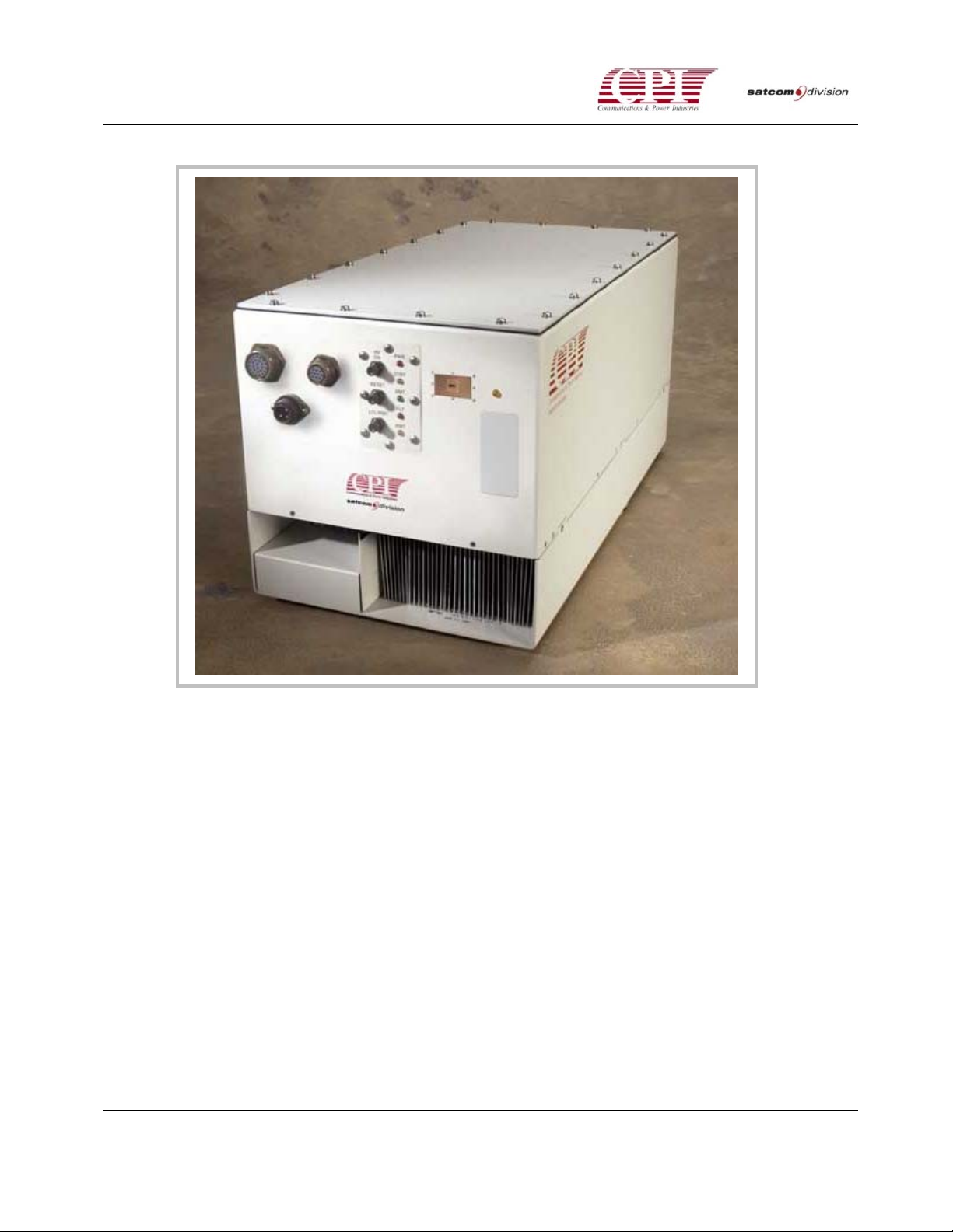
Table 1-1 shows the model numbers, frequency ranges, and power outputs of these amplifiers.
Figure 1-1 is a photograph of a Ka-Band TWT Amplifier. All models have the same appearance.
Table 1-1. Ka-BAND TWT Amplifiers
Model Number
T02KO 27.5 to 31.0 GHz 250W Peak
T03KO 27.5 to 31.0 GHz 250W CW
By industry convention, the rated power of an amplifier is the output power of the high poweramplifying component, a traveling wave tube (TWT). The output power available to the user at
the amplifier output flange is lower. Peak power amplifiers offer the same linear power as their
CW (Continuous Wave) counterparts, except their rated CW power is typically 1.5 to 3dB below
their peak rating. Depending on model selected, the operating frequency range and rated CW
power level will vary.
Frequency Range
(GHz)
Rated Power
(Watts)
DOC.01031492 REV.3
1-1
KA BAND OUTDOOR TWT AMPLIFIER
Figure 1-1. Ka-Band TWTA (Front View)
The Ka-Band TWTAs operate with AC input (line) voltages of 100 - 240 ± 10% V
at any
AC
frequency between 47 and 63 Hz.
All of the Ka-Band TWTAs are the same size and nearly the same weight. The typical model
weighs 52 pounds (23.6 kg.), the overall dimensions, excluding switches, connectors, and handles
and mounting brackets, are 10.25 by 9.5 by 20.0 inches (260.4 X 508 X 241.3 mm).
These amplifiers are air-cooled. The cooling air enters the bottom of the unit and exits the rear
end. A feature standard in Ka Band TWTAs regulates the fan speed control, using a sensor to vary
the speed with TWT temperature. This greatly increases the fan life while reducing acoustical
noise. (See Chapter 2 for more details.) Care should be taken to ensure the airflow path is not
blocked. If the amplifier is to be powered up on a test bench, then it should be set on blocks or
mounting brackets to prevent airflow blockage. Ka-Band TWTAs can operate in direct sunlight at
ambient temperatures ranging from –40 to + 60°C.
Detailed specifications for the Ka-Band TWTAs ODU are provided in Chapter 7, "Drawings”.
1-2
INSTALLATION AND OPERATION MANUAL
R
The Ka-Band TWTAs can be operated in either local or remote mode, the latter being the primary
mode of operation. Remote operation is performed using either a CPI Remote Control Unit or a
user-supplied IBM compatible computer.
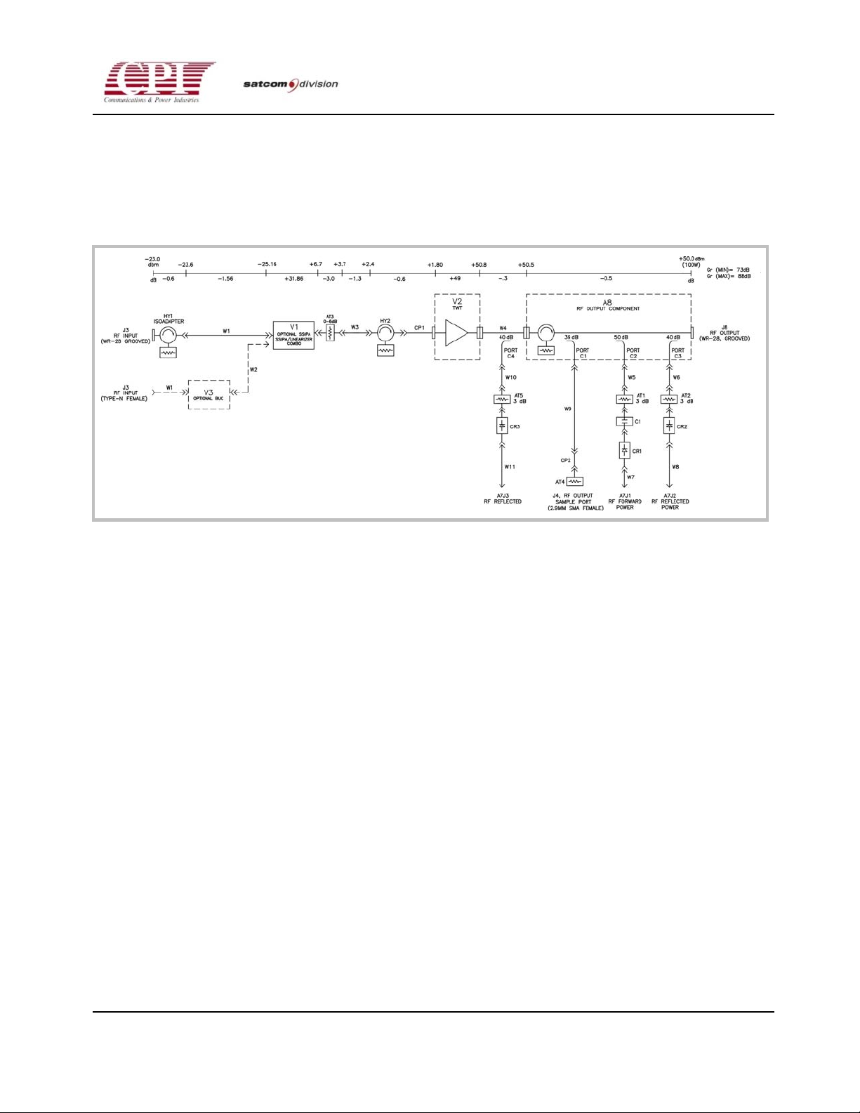
The RF Block diagram is shown in Figure 1-2.
KA BAND OUTDOOR TWT AMPLIFIE
Figure 1-2. Typical Ka-Band TWTA RF Diagram
1.2 Optional Features
The Ka-Band TWTA has five main internal optional features:
• An IPA Option (with pin diode attenuator)
• A Linearizer option
• An internal 1:1 switch controller with drive option.
• An internal hybrid or 1:2 switch controller with drive option.
• A separate Ka-Band TWTA Remote Control Unit is also available.
1.3 About This Manual
This manual describes the Ka-Band TWTA installation and operation procedures.
The Safety section that precedes Chapter 1 provides practical guidelines regarding High Voltage
and Microwave Radiation operating practices.
DOC.01031492 REV.3
1-3

KA BAND OUTDOOR TWT AMPLIFIER
Chapter 1, “Introduction”, contains a brief overview of the amplifier and this manual.
Chapter 2, “Unpacking and installation”, contains procedures for unpacking and installing the KaBand TWTA.
Chapter 3, “Initial Power ON and Checkout”, describes the controls and indicators on the front panel
of the amplifier, the CPI Remote Control Unit controls and indicators, and the procedures to use
for initial checkout after the amplifier has been installed.
Chapter 4, “Interfaces”, describes:
• The ODU Amplifier external interfaces and external connector pinouts.
• The commands used to setup the serial interface hardware characteristics.
Chapter 5, “Operation,” describes the procedures for normal start-up and shutdown, and describes
the operational modes of the amplifier.
Chapter 6, “Maintenance,” describes the procedures for scheduled maintenance and the procedures
for return of equipment to CPI.
Chapter 7, “Drawings,” contains relevant engineering drawings and specifications.
The Appendices contain additional topics such as “Service and Warranty.” information and
optional features.
1.4 Conventions
The following symbols and conventions are used in this manual. These symbols differ slightly
from International symbols to emphasize the specific nature of the hazards.
1.4.1 Notes and Cautions
NOTE: Notes provide additional commentary or technical information.
CAUTION! Cautions identify conditions, operations, or procedures
that could potentially damage the equipment.
1-4
INSTALLATION AND OPERATION MANUAL
R
KA BAND OUTDOOR TWT AMPLIFIE
1.4.2 Warnings
There are three different warnings, Electrical Hazards, Radiation (microwave) Hazards, and
Physical Hazards (mechanical, chemical, miscellaneous).
ELECTRICAL HAZARD! DENTIFY CONDITIONS, OPERATIONS, OR
PROCEDURES THAT EXPOSE THE OPERATOR TO POTENTIALLY LETHAL
HIGH VOLTAGES.
RADIATION HAZARD! IDENTIFY CONDI T IONS, OPERATIONS, OR
PROCEDURES THAT EXPOSE PEOPLE TO MICROWAVE RADIATION
SOURCES THAT COULD CAUSE SERIOUS INJURIES, PARTICULARLY TO
YOUR EYES.
PHYSICAL HAZARD! IDENTIFY CONDITIONS, OPERATIONS, OR
PROCEDURES THAT COULD INDUCE STRAIN, MAIM, OR KILL PEOPLE.
THIS INCLUDES HEAVY WEIGHTS, SHARP EDGES OR PROTRUSIONS,
AND CHEMICAL HAZARDS.
1.4.3 Text Conventions
When operator action is required for software entries, the action required is capitalized and the
action object is capitalized and may be bold for emphasis. For example, PRESS ENTER.
Labels for Front Panel controls and indicators are capitalized, (e.g., RESET). Sometimes the actual
labels are abbreviated (e.g., TWT TEMP).
References to other parts of the manual are shown in Italics, such as "See Chapter 6, Operator
Maintenance."
DOC.01031492 REV.3
1-5

KA BAND OUTDOOR TWT AMPLIFIER
This page is intentionally left blank.
1-6
INSTALLATION AND OPERATION MANUAL

R
2-1
KA BAND OUTDOOR TWT AMPLIFIE
CHAPTER 2
Unpacking And Installation
2.1 Overview
This chapter contains instructions for unpacking and installing the Ka-Band TWTA.
2.2 Pre-Inspection
Inspect the exterior of the shipping container(s) for evidence of damage in shipment. If damage is
evident, immediately contact the carrier that delivered the equipment and submit a damage
report. Failure to do so could invalidate future claims.
2.3 Unpacking
Carefully unpack and remove all items from the shipping container(s). Inspect the interior of the
container for damage. Save all packing material until all inspections are complete. It is
recommended that all packing material be saved for potential future use. Verify that all items
listed on the packing slips have been received.
Inspect all items for evidence of damage in shipment. If damage seems evident, immediately
contact the carrier that delivered the equipment and file a claim. Failure to do so could invalidate
future claims.
2.4 Installation
Installation of the Ka-Band TWTA includes:
• Mechanical installation
• Electrical power connections
• Remote control interface
• RF connections
DOC.01031492 REV.3
2-1

KA BAND OUTDOOR TWT AMPLIFIER
2.4.1 Amplifier Installation
Refer to the appropriate Outline Drawing in Chapter 7 “Drawings” for outline and mounting
information.
The amplifier may be mounted using the six tapped holes located on the side (refer to the Outline
Drawing, 01031382, in Chapter 7, “Drawings”). These holes are ¼-20 UNC-2B thread and are 0.50
inch deep. In order to provide secure mounting, screws with locking hardware must be used in all
six holes.
If the amplifier is mounted to an antenna, the structure must be capable of supporting the
additional load of the amplifier plus any wind loading effects, which may occur. It is
recommended that locations subject to electrical interference, such as that from motor contactors,
be avoided.
The amplifier is air-cooled. The intake and exhaust areas must not be blocked. For further
information see the outline drawing and the yellow Operational Warnings document located at
the front of this manual.
2.4.2 Cooling Considerations
The Ka-Band TWTA is forced air-cooled by an internal fan that draws air into the bottom of the
unit. The air is exhausted through ducts located on the front panel. Refer to outline drawing,
01031382, in Chapter 7, “Drawings”.
To insure proper operation of the amplifier, the following guidelines must be observed:
• There must be at least two inches of clearance on the bottom of the unit (air intake).
• There must be at least four inches of clearance on the end of the unit that has the
exhaust ducts (the end with the visible cooling fins).
• The hot exhaust air must be directed away from the air intake area.
• The area below the air intake must be free of foreign material, loose dirt, debris,
and any other material that may be drawn toward the unit and block the air intake
area.
2-2
INSTALLATION AND OPERATION MANUAL

R
KA BAND OUTDOOR TWT AMPLIFIE
2.4.3 Electrical Power Connections
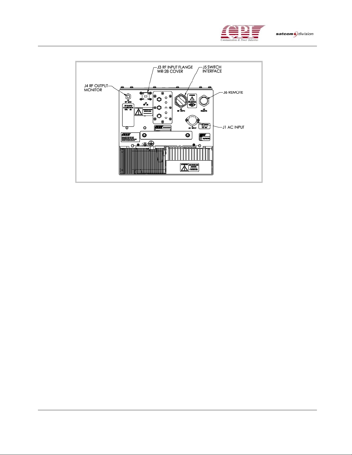
All electrical connections to the amplifier are located on the front panel (Figure 2-1).
2.4.3.1 Prime Power (J1)
ELECTRICAL HAZARD! ELECTRICAL HAZARD! DO NOT APPLY POWER
TO THE AMPLIFIER UNTIL YOU ARE DIRECTED TO DO SO IN THE
Prime power is applied to connector J1 (AC IN) located on the front panel of the amplifier. Prime
power is 100 - 240V
located on exhaust end of unit. A prime power mating connector is supplied in the ship kit with
the unit. The pins of the prime power connector should be wired as follows:
PROCEDURE.
+/- 10% (nominal), 47-63 Hz. The proper voltage is indicated on a label
AC
• Pin 1 - line (or Phase A)
• Pin 2 – No connection
• Pin 3 - Neutral (or Phase B)
• Pin PE – Ground
Prepare the prime power cable but do not connect the cable to the amplifier at this time.
2.4.3.2 Grounding
Proper grounding of the Ka-Band TWTA ODU amplifier to the station ground bus or to earth
ground is necessary for personnel and equipment safety. The 6-32 threaded ground hole on the
amplifier front panel is used for grounding. #14AWG wire or larger is recommended for the
grounding cable.
The amplifier should be protected against lightning.
DOC.01031492 REV.3
2-3
KA BAND OUTDOOR TWT AMPLIFIER
Figure 2-1. Ka-BAND TWTA Connector Locations
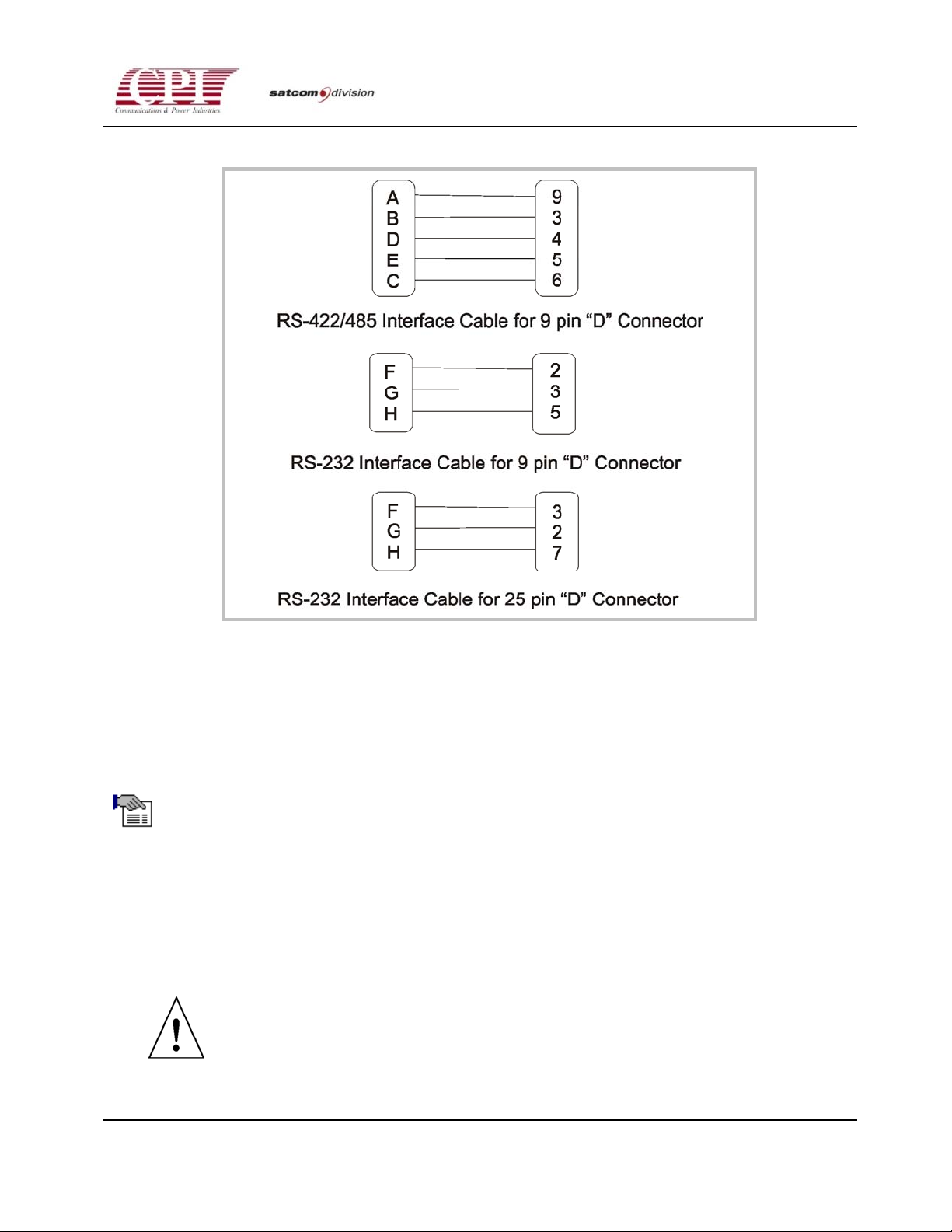
2.4.4 Remote Control Interface (J6)
The operator can use either a PC or the optional CPI Remote Control Unit connected to J6
(“REMOTE”) to remotely monitor and control the amplifier. J6 is a 10-pin MS type connector, ITT
Canon KPT07E12-10S. (A mating connector is supplied in the ship kit.) The PC can use either RS232 or RS-422/485 communication standards, while the CPI Remote Control Panel uses only RS-
422.
Default settings are as follows: STX/ETX protocol, 9600 baud rate, even parity, seven (7) data bits,
with one (1) start bit and one (1) stop bit. The operator may change these settings. Refer to
Drawings (chapter 7) for the Computer interface protocol document.
Interconnect cables should be wired for either RS-232 or RS-422/485, but not both. A cable
assembly similar to CPI drawing 01032322 (see Chapter 7) should be used for RS-422/485
communication. A wiring diagram for a cable using RS-232 is shown in Figure 2-2.
2-4
INSTALLATION AND OPERATION MANUAL
R
KA BAND OUTDOOR TWT AMPLIFIE
Figure 2-2 RS-232 Cables
2.4.5 Switch Interface Connector (J5)
Connector J5 is a round 26-pin female (socket) connector that is used for redundant system
operation.
NOTE: A mating, wired connector (jumper plug) is supplied with the
unit. If the amplifier is to be used in a standalone configuration, this
connector must be used.
2.4.6 RF Coaxial Cable Connections (J4)
Refer back to Figure 2-1 for connector locations. A power monitor cable can be connected directly
to front panel connector J4 (40 dB nominal coupling). Tighten the connector.
CAUTION! Position the coaxial cables so that there is no stress
on connectorJ4.
DOC.01031492 REV.3
2-5

KA BAND OUTDOOR TWT AMPLIFIER
CAUTION! Only use a 2.92mm SMA or “K” type connector. Other
connector types will NOT properly interface with J4, and could
cause damage to the connector center conductor.
2.4.7 RF Input Waveguide Flange Connection (J3)
The input waveguide flange of the Ka-Band TWTA is located on the front panel (Figure 2-1). The
mating connection is WR-28G grooved waveguide flange with four through holes (4-40 clearance).
An O-ring gasket is supplied in the ship kit in Chapter 7, “Drawings”.
To install the waveguide flange, proceed as follows:
1. Install the O-ring gasket (supplied) in the input flange.
2. Position the interconnecting waveguide so that it aligns precisely with the waveguide
flange at the rear of the Ka-Band TWTA.
CAUTION! If flange alignment is not precise or if the installation
is subject to motion or severe vibration, a flexible waveguide
section should be installed between the output of the Ka-Band
TWTA and the interconnecting waveguide.
3. After alignment is verified in all three planes, loosely attach the interconnecting waveguide
to the input waveguide flange of the Ka-Band TWTA with 4-40 stainless steel screws, flat
washers, lock washers, and nuts. Start all bolts and verify proper alignment.
4. A progressive tightening procedure is recommended. Tighten each bolt until the lock
washer starts to compress and then proceed to the next bolt, until you have partially
tightened all the bolts.
5. Starting with the first bolt, fully tighten them to the desired torque level (4.3 in. lbs. for 4-40
screws). Do not over-tighten the screws because this can strip the threads or distort the
mating flange.
2.4.8 RF Output Waveguide Flange Connection (J8)
The output waveguide flange of the Ka-Band TWTA is located on the rear panel (Figure 2-3). The
mating connection is either a WR-28 or WR-34 flat waveguide flange with four through holes (4-40
clearance), depending on which option was specified at the time of order. An O-ring gasket is
supplied in the ship kit in Chapter 7, “Drawings”.
To install the waveguide flange, proceed as follows:
2-6
INSTALLATION AND OPERATION MANUAL
 Loading...