

CPI OLIVER CITY, OLIVER SPORT Owner's Manual

Page 1 from 37
Dear customers!
First of all thank you for buying a vehicle from
our company. Before starting to ride your new
vehicle, we recommend to read this user guide
very careful. It contains a lot of important
information and advices for the correct use. This
user guide is one part of the equipment of the
vehicle and at the sale it must be handed over to
the owner.
We reserve the right to make technical
modifications on the vehicles without changing
the characteristic features of them. We are not
responsible for mistakes in the translation or the
printing of the user guide. If you have any
questions, please contact one of our authorized
dealers.
We wish you a lot of fun and a good start with
your new vehicle.

Page 2 from 37
Index
1. General information
1.1 Prior starting vehicle
1.2 Modifications on the vehicle
1.3 Important code numbers on the vehicle
2. Parts location
3. Various parts operation
3.1 Dashboard
3.1.1 Speedometer
3.1.2 Odometer
3.1.3 Oil level indicator
3.1.4 High beam indicator
3.1.5 Direction light indicator
3.1.6 Fuel indicator
3.1.7 Current time function
3.2 Ignition lock
3.3 Starter button
3.4 Headlight switch
3.5 Dimmer switch
3.6 Horn
3.7 Direction indicator
3.8 Steering lock
3.8.1 Locking
3.8.2 Unlocking
3.9 Helmet box
4. Starting engine
4.1 Starting the engine with electricity
4.2 Kickstarter
5. Correct riding operation
5.1 Start up
5.2 Speed adjustment
5.2.1 Acceleration
5.2.2 Deceleration
5.3 Running in instructions
5.4 Correct braking and turning
5.5 Riding when it rains
5.6 Safety through training
6. How to stop and park
6.1 Stop
6.2 Parking
6.3 Choice of a suitable parking place
7. Inspections before operation
7.1 Fuel
7.2 Steering
7.3 Brakes
7.3.1 Drum brake
7.3.2 Disc brake
7.4 Stop light
7.5 Direction indicator
7.6 Tires
7.7 Shock absorber
7.8 Illumination
7.9 Horn
7.10 Speedometer
7.11 Back mirror
8. Regular maintenance and inspection
8.1 Battery
8.1.1 Removal and assembly of battery
8.2 Fuse
8.3 Bulb replacement
8.3.1 Head light
8.3.2 Direction indicator front and rear
8.3.3 Tail and stop light
8.4 Correct adjustment of low beam
8.5 Inspection of cable rubber parts
9. If engine does not start
10. Safety operation
11. Final thought
12. Technical data
13. Service instructions

Page 3 from 37
1. General ínformation
1.1 PRIOR STARTING VEHICLE
This manual describes matters pertaining to correct operation, safe operation and simple maintenance of
the vehicle you purchased. To ensure more comfortable and safer operation, we recommend to read this
manual carefully prior to operation.
• The photographs and pictures shown in this manual may differ from those of actual vehicles due
to changes in vehicle specifications or made modifications.
• This vehicle is designed for 2 riders including the operator. If you use the vehicle in an irregular
way, you aren’t eligible for any warranty claim.
• Check the vehicle before your first trip.
• Keep the vehicle clean and conduct all specified maintenance inspections.
• Make sure to stop engine and stay away from fire when refuelling.
• Exhaust gas contains harmful substances such as carbon monoxide. Start engine at well-
ventilated places.
1.2 MODIFICATIONS ON THE VEHICLE
All modifications on the vehicle, as the increase of cylinder capacity, the engine output or speed, change
the characteristic features of the vehicle category. Additional this is prohibited by law and will be
prosecuted. If you ride without any driving license you take a risk that your vehicle will be confiscated and
must be checked and admitted again through the appropriate authority.
Also note, that all modifications regarding the exhaust emission characteristics and noise behaviour
cause the expiry of the driving license.
Furthermore all modifications at illuminiation, license plate, license plate holder, acustic warning devices
or back mirrors are not allowed by law and you haven’t an insurance coverage anymore. Pay attention
that all above mentioned modifications are not covered by warranty and releases the
manufacturer from any liability. Use only genuine parts respectively parts which are recommended
from the manufacturer or authorized dealer. The dealers offer a wide range of accessories which conform
to any technical, functional and aesthetic features of the vehicle and comply to the road traffic regulations.
The fitting of not original accessories, as wind shield, top case may affect your riding safety and
is possibly subject to authorisation. The use of accessories or spare parts not released through the
vehicle manufacturer could cause the expiry of any warranty claim.
Attachment
• Do not add electrical equipment (radio, illumination) - that will exceed the vehicle’s electrical system
capacity.
Page 4 from 37
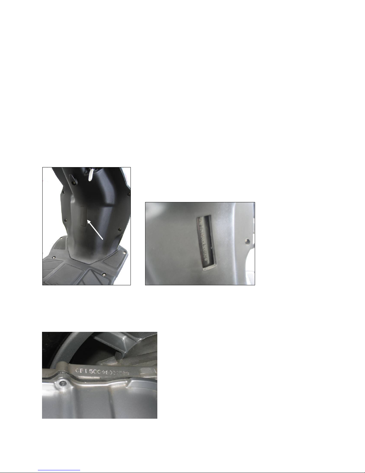
1.3 IMPORTANT CODE NUMBERS ON THE VEHICLE
The vehicle has following code numbers:
– vehicle identification number
– engine number
– license plate
Record the vehicle identification number and the engine number along with the vehicle license plate
number and keep them separately from the vehicle.
Any modification of the VIN is not allowed.
Before licence of the vehicle, it is important to compare the VIN on your vehicle with the VIN mentioned in
your vehicle documents.
Vehicle identification number:
The VIN (17-digit) is important for its explicit identification and is needed for registration at the
responsible authority.
It is stamped on the frame as you can see on the picture.
Engine number
The serial number of the engine is stamped on the top of the lh crank case.
Page 5 from 37
(
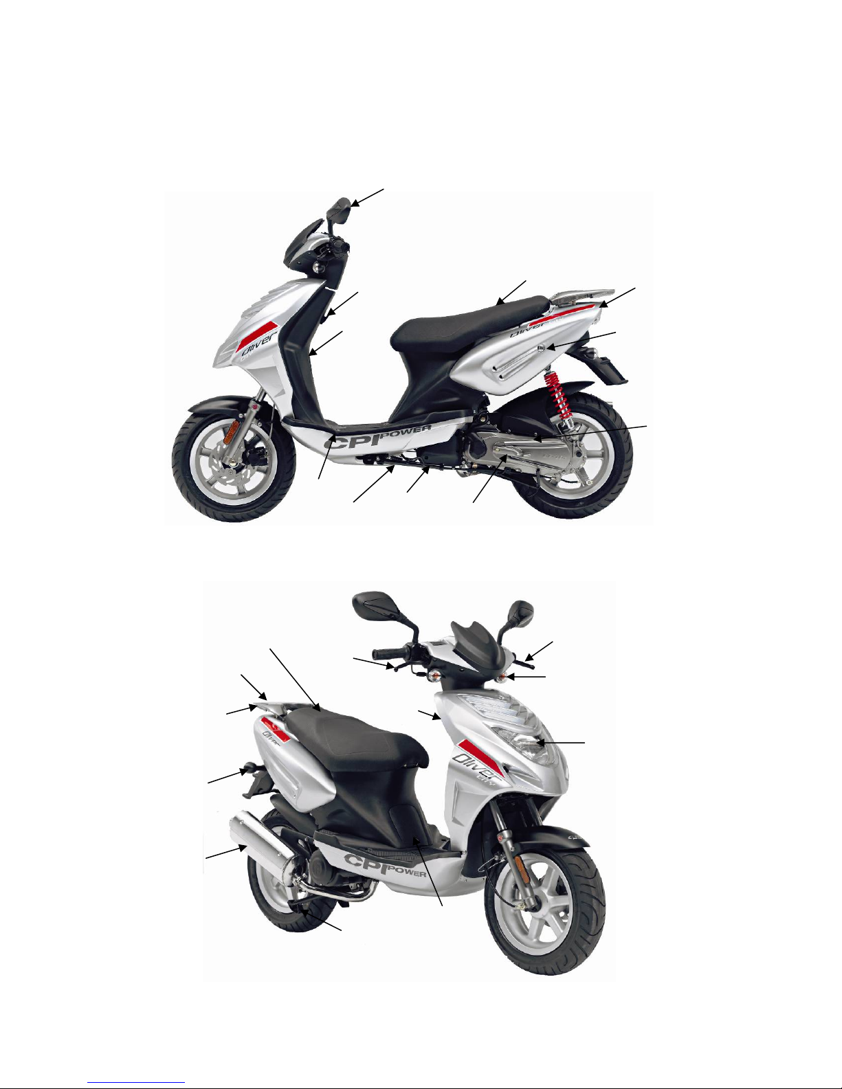
2. PARTS LOCATION
OLIVER CITY
Back mirror
Luggage holder
Type plate
Anti tampering plate
under the seat)
Seat lock
Tail/stop light
Engine number
Battery
Side stand
Air filter
Kickstarter
Brake lever for
rear wheel
Direction indicator
Head light
Fuel tank
Luggage carrier
Direction indicator
Exhaust
Helmet box
Brake lever for
front wheel
Ignition lock
Oil tank
Main stand
Page 6 from 37
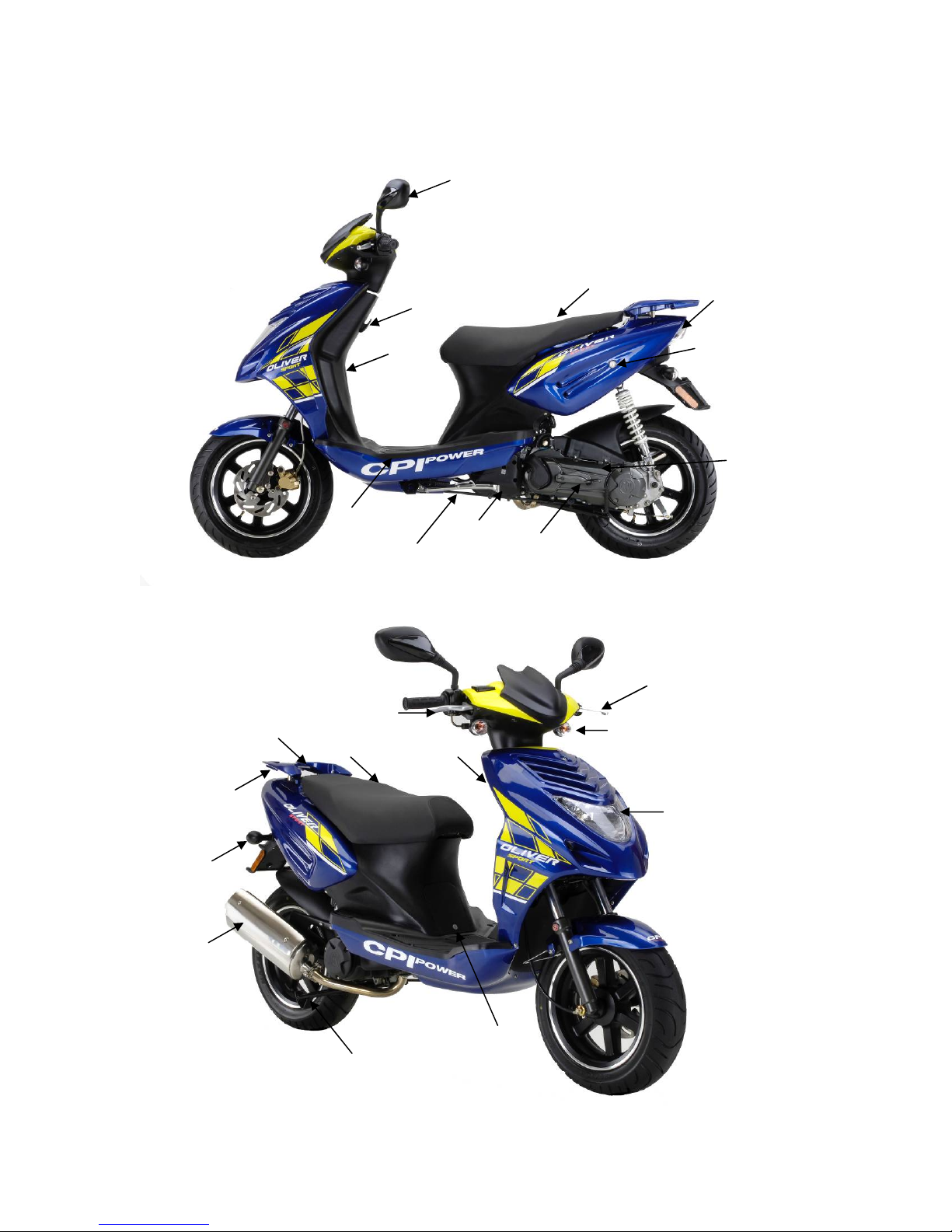
r
Direction
indicator
Exhaust
Fuel tank cap
Luggage
carrie
Battery
Side stand
Brake lever for
front wheel
Helmet box
Main stand
OLIVER SPORT
Back mirror
Luggage holder
VIN
Air filter
Kickstarter
Ignition lock
Oil tank
Type plate
Anti tampering plate
(under seat)
Brake lever for
rear wheel
Direction indicator
Tail/stop light
Seat lock
Engine number
Head light
Page 7 from 37
3. Various parts operation
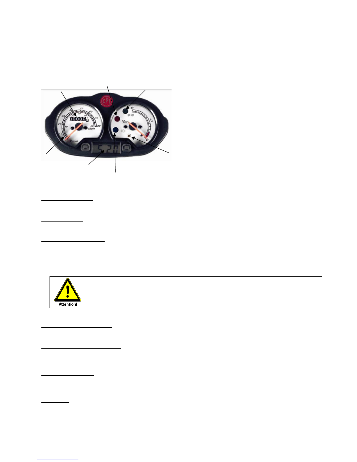
3.1 DASHBOARD
Odometer
Oil indicator
Direction light indicator
Speedometer
Time
High beam indicator
Fuel level indicator
3.1.1 Speedometer
• The standard speed indication is km/h.
3.1.2 Odometer
• Total forward distance is indicated in km. The white digits on black background indicate 100- m-units.
3.1.3 Oil level indicator
• If the oil level drops below the MIN-marking in the oil tank, the oil indicator is lighting on the display.
Stop your vehicle immediately and fill up engine oil of specification mentioned in the maintenance
schedule.
• After changing oil and turning the key to “ON”, the oil level indicator has to go out.
Check the function of the oil level indicator by turning the ignition key to the position
between “ON” and “OFF”. In this position the oil level indicator has to light up. Generally
we recommend to check a satisfactory oil level always when you fuel the vehicle.
3.1.4 High beam indicator
• When operating the high beam indicator the symbol for high beam is lighting on the display.
3.1.5 Direction light indicator
• When operating the left or right direction indicator, the relative symbol for the left- or right hand side is
blinking on the display.
3.1.6 Fuel indicator
• It indicates the fuel volume in the fuel tank. If the fuel level reaches the reserve fuel area, the fuel
indicator is lighting on the display. Refuel as soon as possible.
3.1.7 Time
• The time will be indicated in hours and minutes.
Page 8 from 37
• Through pressing the rh mode-button the date will be indicated for about 4 sec.
• Through shortly pressing the lh mode-button the date and the time appear alternately.
• Through pressing the rh mode-button twice, the seconds will be indicated on the displ ay. To reset,
press the lh mode-button twice. Through pressing the rh mode-button the adjustment will be confirmed
and the time will be indicated on the display.
• Through pressing the lh mode-button twice, the month will be indicated. Adjustment through pressing
the rh mode-button, confirmation through pressing the lh mode-button. The display indicates the day –
adjustment through pressing the rh mode-button and confirmation through pressing the lh modebutton.
• The display indicates the hours – adjustment through pressing the rh mode-button and confirmation
through pressing the lh mode-button. The display indicates the minutes – adjustment through pressing
the rh mode-button, confirmation through pressing the lh mode-button.
• Through pressing the rh mode-button the adjusted time now will be indicated on the display.
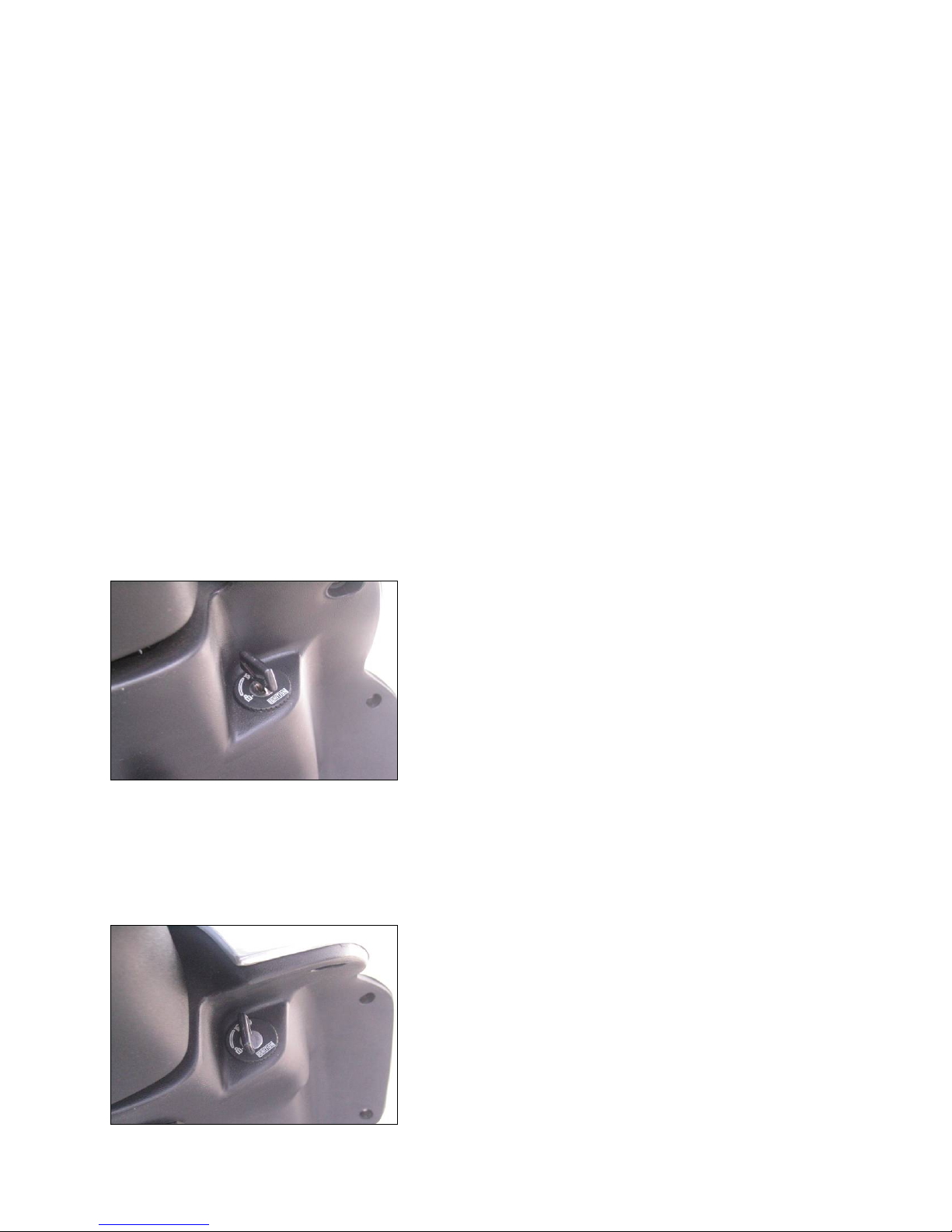
3.2 IGNITION LOCK
Due to the ignition lock it’s possible to start or stop the engine. The ignition lock is placed below the
operating elements.
Off
• The electric circuit of the vehicle is intermitted, the engine cannot be started.
• Key can be placed in or taken out of the ignition lock.
On
Page 9 from 37
• The electric circuit of the vehicle is connected, the engine can be started.
• Key cannot be pulled out.
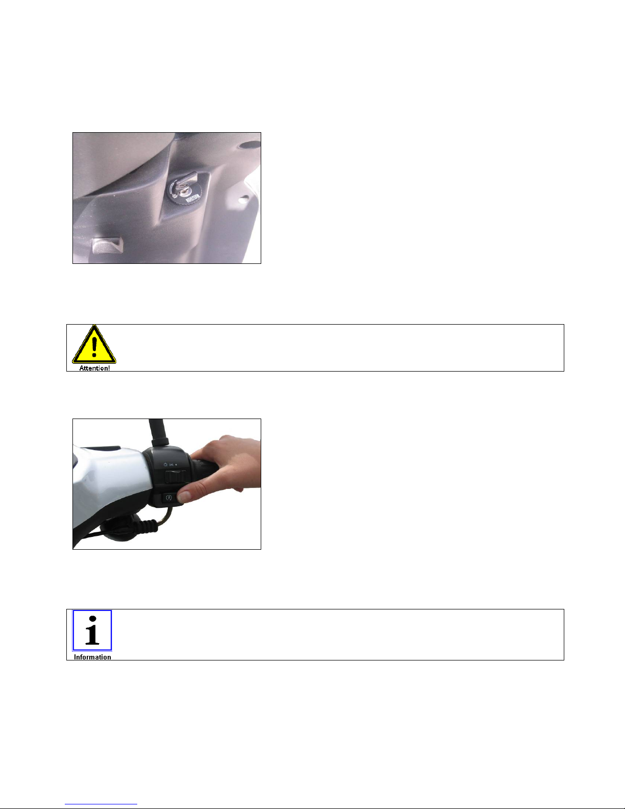
Lock
• The electric circuit of the vehicle is intermitted, the engine cannot be started and the steering is
locked.
• Key can be placed in or taken out of the ignition lock.
Never operate the ignition key during travel as it might cause unexpected
accidents. If it is necessary to remove the ignition key, stop the vehicle.
3.3 STARTER BUTTON
• The starter button is placed next to the throttle grip. Due to pressing the starter button and pulling the
brake lever, the engine can be started (ignition key must placed to “ON” position). (See „starting off
engine“, chapter 4).
Do not press the starter button longer than 4 sec., as the starting motor consumes a
lot of electricity and this discharges the battery.
Page 10 from 37
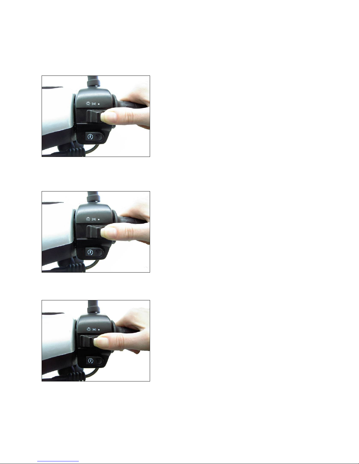
3.4 HEADLIGHT SWITCH
Off
• Light switched off
Parking light
• Parking light, dashboard light and tail light are turned on.
Driving light
• Driving light turns on.
Page 11 from 37
h
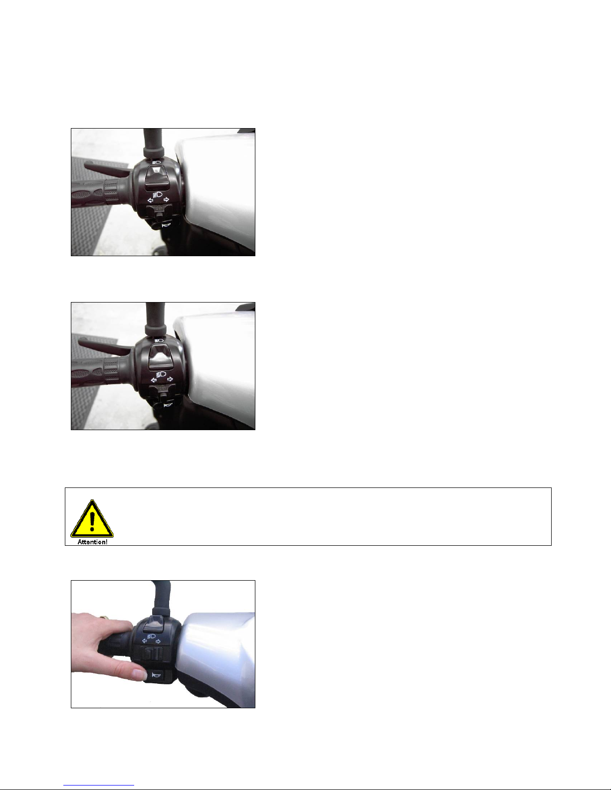
3.5 DIMMER SWITCH
1. High beam
In this position the high beam is turned on.
2. Low beam
In this position the low beam is turned on.
3. Headlamp flasher
Through keep pressing the high- and low beam switch the high be am is lighting.
• Use the high beam only in the suburban. Take care to the other road users when
using the high beam!
3.6 HORN
• The horn sounds if the horn button is pressed and the ignition key is in “ON” position.
Page 12 from 37
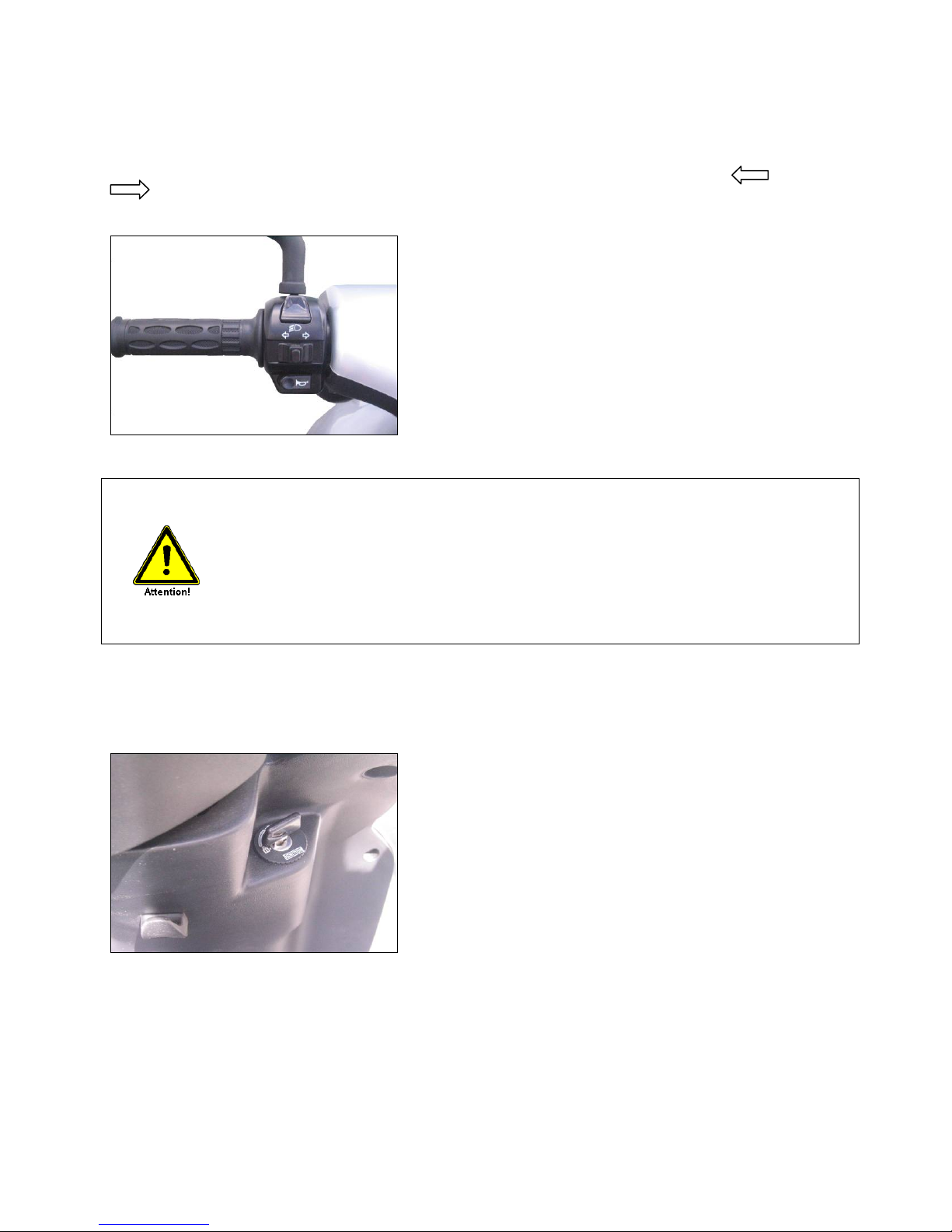
3.7 DIRECTION INDICATOR
To activate the direction indicator, you have to turn the ignition key to “ON” position. Depending in which
direction you want to ride, you have to press the button into the left or right
position. To switch off the direction indicator, press the button.
• You have to use the direction indicator while turning or changing lines and
if necessary when you start or stop to ride.
• If the direction indicator is used, this will be signalized through the direction
light indicator on the dashboard.
• The direction indicator does not stop automatically. You have to stop it manual
through pushing the button.
Please note, that you can endanger other road users and yourself if you don’t
switch off the direction indicator after turning.
• The direction indicator does only work when the ignition key is in “ON” position.
3.8 STEERING LOCK
• When parking, make sure to lock steering to prevent theft of the vehicle.
3.8.1 Locking
• Turn the steering to the left, push the ignition key soft and turn it at the same time into the LOCK
position. Take off the ignition key.
3.8.2 Unlocking
• Turn the ignition key clockwise and move the steering handle lightly in both directions.
 Loading...