


CPCLARE TG-226, TG-225, TG-224, TG-222, TG-221 Datasheet
...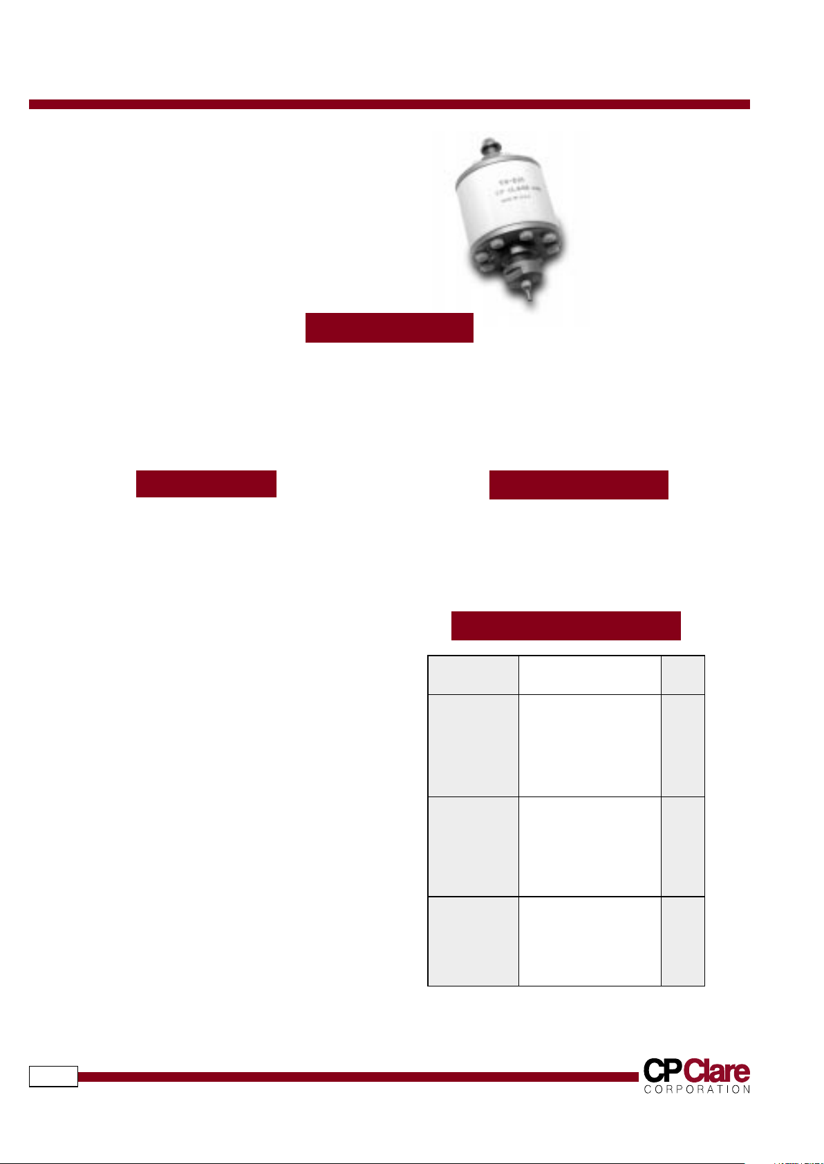
HIGH-ENERGY TRIGGERED SPARK GAPS
558
DESCRIPTION
North America: 1-800-CPCLARE Europe: 32-11-300868 Asia: 886-2-2523-6368 Japan: 81-3-3980-2212
T riggergaps
DESCRIPTION
STANDARD VOLTAGES
APPLICATIONS
FEATURES
CP Clare's Triggergaps are high-energy spark gaps that are capable of switching stored energy in a fraction of a
microsecond. Triggergaps require no standby power, are extremely rugged, and require only a low-energy, highvoltage triggering pulse. The miniature TA series (1-15kV) provides switching capability for pulses with energy
content as high as 50 joules. The larger TB series (2.5-25 kV) will reliably switch pulses with up to 300 joules of
energy. The TG-221 to 226 (1-60 kV) can switch pulses with energy contents of up to 6000 joules and feature
adjustable self-breakdown voltages.
■
Tight self-breakdown voltage tolerance
(±10%;TA & TB series)
■
Adjustable self-breakdown voltage
(TG-221 to TG-226)
■
Rugged ceramic-metal construction
■
Refractory metal electrodes
■
Corrosion-resistant stainless steel
external surfaces (TB series)
■
High current surge generators
■
Exploding bridge wire systems
■
Crowbars
■
Flashtube triggers
Series or P/N Self-Breakdown Units
Voltage (typ)
TA 1.0 kV
2.0 kV
5.0 kV
7.0 kV
10.0 kV
15.0 kV
TB 2.5 kV
5.0 kV
10.0 kV
15.0 kV
20.0 kV
25.0 kV
TG-221 1.0-20.0 kV
TG-222 18.0-40.0 kV
TG-224 1.0-20.0 kV
TG-225 18.0-40.0 kV
TG-226 35.0-60.0 kV
HIGH-ENERGY TRIGGERED SPARK GAPS
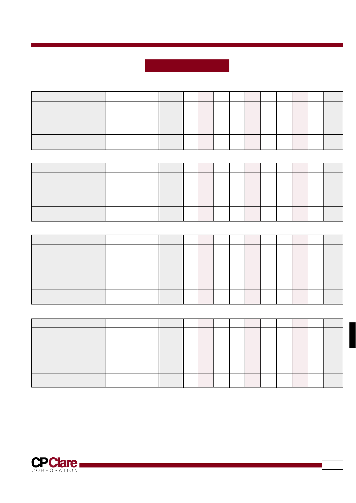
SPECIFICATIONS
559
www.cpclare.com
Triggergaps
All characteristics at 25˚C
TA-1.0 TA-2.0 TA-5.0
PARAMETER CONDITIONS SYMBOL MIN TYP MAX MIN TYP MAX MIN TYP MAX UNITS
Device Specifications
Self-Breakdown Voltage 100V/s E
Z
0.9 1.0 1.1 1.8 2.0 2.2 4.5 5.0 5.5 kV
Applied Voltage E
bb
0.4 - 0.85 0.7 - 1.7 1.2 - 4.2 kV
Trigger Voltage
1
tr=0.5µs, PW=3.0µse
trig
3.0 - 2.5 3.0 - 2.5 3.5 - 2.5 kV pk
Dimension A - 0.687 0.750 0.813 0.697 0.760 0.823 0.697 0.760 0.823 inches
Life Ratings
Discharge Life
2
≥1000 shots into .2Ω - 45- -50- -50- - J
TA-7.0 TA-10.0 TA-15.0
PARAMETER CONDITIONS SYMBOL MIN TYP MAX MIN TYP MAX MIN TYP MAX UNITS
Device Specifications
Self-Breakdown Voltage 100V/s E
Z
6.3 7.0 7.7 9.0 10.0 11.0 13.5 15.0 16.5 kV
Applied Voltage E
bb
1.9 - 5.8 3.5 - 8.5 7.0 - 12.5 kV
Trigger Voltage
1
tr=0.5µs, PW=3.0µse
trig
3.7 - 2.8 5 - 3.5 8.0 - 4.5 kV pk
Dimension A - 0.697 0.760 0.823 0.727 0.790 0.853 0.767 0.830 0.893 inches
Life Ratings
Discharge Life
2
≥1000 shots into .2Ω - 50- -60- -70- - J
TB-2.5 TB-5.0 TB-10.0
PARAMETER CONDITIONS SYMBOL MIN TYP MAX MIN TYP MAX MIN TYP MAX UNITS
Device Specifications
Self-Breakdown Voltage 100V/s E
Z
2.25 2.50 2.75 4.5 5.0 5.5 9.0 10.0 11.0 kV
Applied Voltage E
bb
0.8 - 2.0 1.5 - 4.0 3.0 - 8.0 kV
Trigger Voltage
1
tr=0.5µs, PW=3.0µse
trig
3.1 - 1.8 3.2 - 1.9 4.6 - 2.1 kV pk
Dimension A - - 1.99 - - 1.99 - - 1.99 - inches
Dimension B - - - 0.23 - - 0.23 - - 0.58 inches
Dimension C - - - 2.03 - - 2.03 - - 2.10 inches
Life Ratings
Discharge Life
2
discharges into .3Ω - 150 - - 150 - - 300 - - J
TB-15.0 TB-20.0 TB-25.0
PARAMETER CONDITIONS SYMBOL MIN TYP MAX MIN TYP MAX MIN TYP MAX UNITS
Device Specifications
Self-Breakdown Voltage 100V/s E
Z
13.5 15.0 16.5 18.0 20.0 22.0 22.5 25.0 27.5 kV
Applied Voltage E
bb
4.5 - 12.0 6.0 - 16.0 7.5 - 20.0 kV
Trigger Voltage
1
tr=0.5µs, PW=3.0µse
trig
6.3 - 3.5 8.0 - 4.5 9.7 - 5.2 kV pk
Dimension A - - 2.67 - - 2.79 - - 2.79 - inches
Dimension B - - - 0.58 - - 0.58 - - 0.58 inches
Dimension C - - - 2.10 - - 2.10 - - 2.10 inches
Life Ratings
Discharge Life
2
discharges into .3Ω - 300 - - 300 - - 300 - - J
1
The trigger voltages given in these tables are the minimum triggering voltages necessary for triggering at the corresponding applied voltage limits. As the applied trigger voltage
increases, the trigger voltage required for triggering decreases. It is assumed that the trigger is applied across the trigger and adjacent main electrodes — higher trigger voltages are
required if it is applied across the trigger voltage and opposite main electrodes.
2
End point for life testing is a 15% reduction in the self-breakdown voltage.
3
Because the self-breakdown voltage of these devices is adjustable, the trigger voltage required for any particular applied voltage cannot be specified. Clare suggests setting the self-
breakdown voltage to at least 115% of the maximum applied voltage.