

CPCLA CYG2320, CYG2300 Datasheet

1
www.clare.com
CYG23XX
DS-CPC2300-R1
Clare’s CybergateTM23XX DAA modules provide a complete telephone line interface circuit in a small 1.07" x
1.07" x 0.4" package. This module provides a fast and
cost effective solution for designs that require an interface
to the telephone line. The CYG23XX0 is designed to
meet PTT and safety regulations in Germany.
• Home medical devices
• Plant monitoring equipment
• Security/alarm systems
• Utility meters
• Modems
• Voicemail systems
• Vending machines
• Elevator control boxes
• Network routers
• PBX Systems
• PC mother boards
• Telephony applications
• Digital telephone answering machines
• BSI Approved to EN60950
Certification #: 8123
• Low distortion transformer signal coupling
• Complete ring detector circuit
• Low power hookswitch
• Electronic inductor/gyrator circuit
• Surge protection
• V.32 bis /V.34 compatible
• PC board mountable
• 16kHz metering filter
Applications
Features
Description
Approvals
CYBERGATE™
Ordering Information
Part # Description
CYG2300 DAA Module Germany
CYG2320 DAA Module Australia
Block Diagram
Handling and Assembly Recommendations
The CYG23XX products are not hermetically sealed and should not be exposed to any liquid-based rinsing processes. Clare recommends two (2) approaches. The
modem should either use a no clean soldering flux that would mostly evaporate during the normal wave soldering processes, or be soldered in by hand after the rest
of the card is wave soldered.
HYBRID
CIRCUIT
5
3
RING
OH
Rm
560
1
2
10
6
7
11
4
TO TELEPHONE LINE
GYRATOR
SURGE
PROTECTOR
RING
DETECT
NETWORK
V
CC
V
CC
470Ω
56kΩ
HOOKSWITCH
V
CC
LINE 2
LINE 1
MUTE
RING
GND
GND
V
CC
TX1
TX2
RX
OH RELAY
RING
TIP
4.3V
4.3V
FROM µC
www.clare.com
CYG23XX
Rev. 1
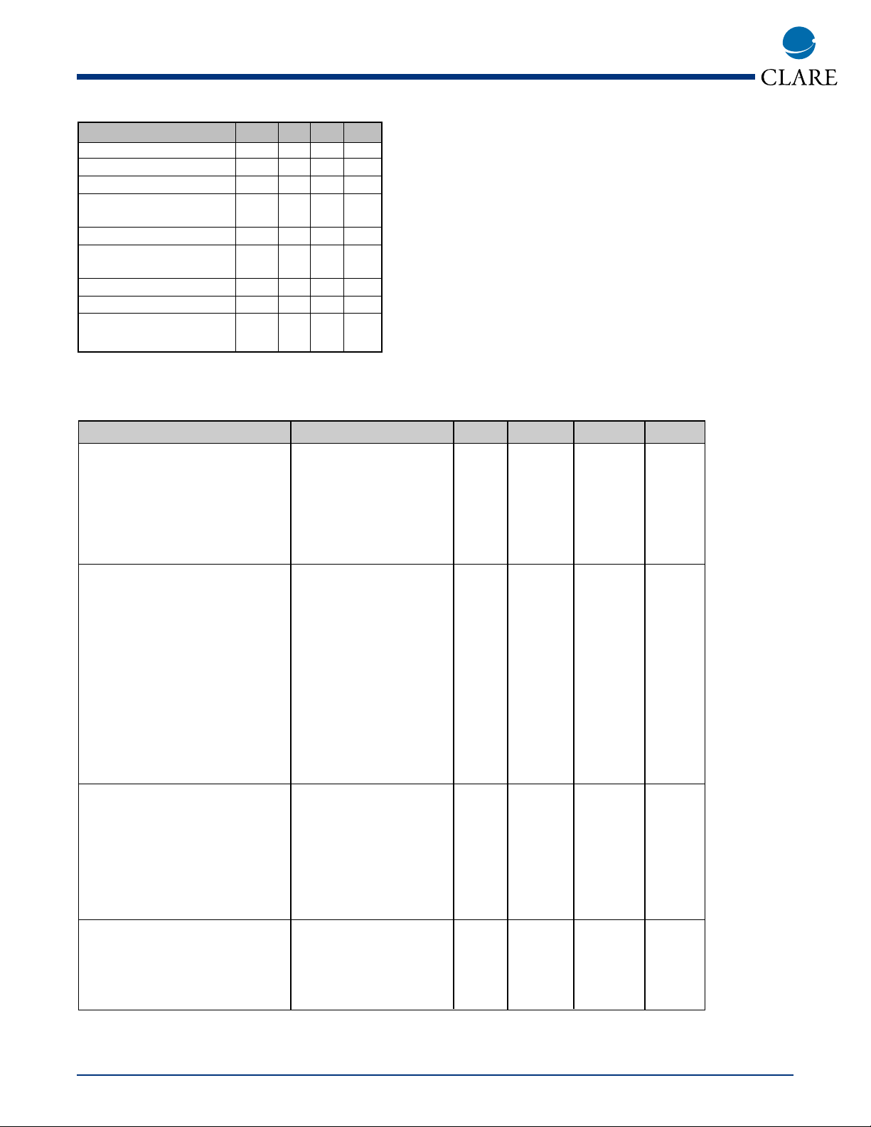
Electrical Characteristics
Absolute Maximum Ratings are stress ratings. Stresses in
excess of these ratings can cause permanent damage to
the device. Functional operation of the device at these or
any other conditions beyond those indicated in the operational sections of this data sheet is not implied. Exposure
of the device to the absolute maximum ratings for an
extended period may degrade the device and effect its
reliability.
Absolute Maximum Ratings (@ 25˚ C)
2
Parameter Conditions Min Typ Max Unit
DC Electrical Characteristics
On-Hook Impedance V
Tip
-Ring=100VDC 10 - - MΩ
On-Hook Line Leakage Current V
Tip
-Ring=100VDC - - 10 µA
Off-Hook Relay Supply Current V
CC
=5V 7 8 9 mA
Hookswitch Power Source - 4.75 5.0 20 V
DC Loop Current - 5 - 120 mA
Mute Relay Supply Current VCC=5V 7 8 9 mA
AC Signal Path Electrical
Characteristics
Return Loss f=300-3500Hz 14 25 - dB
Insertion Loss
Transmit Test Circuit 1 - - 7 dB
Receive Test Circuit 2 - - 7 dB
Frequency Response f=300-3500Hz -0.25 - +0.25 dB
Longitudinal Balance
On-Hook - 60 - - dB
Off-Hook - 40 - - dB
Total Harmonic Distortion f=350Hz, P=-10dBm - -80 - dB
Secondary Load Impedance Line 1 and Line 2 - 100 - Ω
Primary Source Impedance Tip and Ring - 600 - Ω
Ring Detection Circuit
Characteristics
Ringing Voltage Detection Range - 29 - - V
RMS
Ringing Frequency Detection Range 50-70Hz 15 - 70 Hz
Ringer Impedance f=25Hz - 18 - KΩ
RING Output Voltage (Pulsed) V
CC
=+5V
Logic ‘0’, Ring present - - 0.8 V
Logic ‘1’, Ring not present - - Vcc V
Surge, Transient, and Isolation
Characteristics
Surge Protection Voltage Tip and Ring - - - 300 V
Isolation Voltage
(Pins 1-7 to 10-11) 60 Seconds - - 1500 V
RMS
Parameter Min Typ Max Units
Isolation Voltage - - 1500 V
RMS
Operational Temperature 0 - 70 °C
Storage Temperature 0 - 100 °C
Relative Humidity 10 - 85 %
(Non-Condensing)
Soldering Temperature - - 260 °C
Tip/Ring Load Current
(continuous) - - 120 mA
Hookswitch LED Drive Current - - 50 mA
Hookswitch LED Reverse Voltage - - 5 V
Ring Detect Phototransistor
Voltage V
CC
--20V
 Loading...