

CPcam CPD537, CPD535, CPD531 User Manual
264Z
CPD531_535_537manual_V1.2
B
B
E
E
S
S
T
T
D
DII
G
GII
T
T
A
A
L
L
S
S
E
E
C
C
U
U
R
RII
T
T
Y
Y
G
G
U
U
A
A
R
R
D
D
S
S
E
E
R
RII
E
E
S
S
Please read instructions thoroughly before operation and retain it for future reference.
The image shown above may differ from the actual product appearance.
IMPORTANT SAFEGUARD
Graphic Symbol Explanation
The lightning flash with arrowhead symbol, within an equilateral triangle, is intended to alert the user
to the presence of uninsulated “dangerous voltage” within the product’s enclosure that may be of
sufficient magnitude to constitute a risk of electric shock to persons.
This exclamation point within an equilateral triangle is intended to alert the user to the presence of
important operating and maintenance (servicing) instructions in the literature accompanying the
appliance.
All lead-free products offered by the company comply with the requirements of the European law on
the Restriction of Hazardous Substances (RoHS) directive, which means our manufacture processes
and products are strictly “lead-free” and without the hazardous substances cited in the directive.
The crossed-out wheeled bin mark symbolizes that within the European Union the product must be
collected separately at the product end-of-life. This applies to your product and any peripherals
marked with this symbol. Do not dispose of these products as unsorted municipal waste. Contact your
local dealer for procedures for recycling this equipment.
CE Mark
This apparatus is manufactured to comply with the radio interference requirements.
Disclaimer
We reserve the right to revise or remove any content in this manual at any time. We do not warrant or assume any
legal liability or responsibility for the accuracy, completeness, or usefulness of this manual. The content of this manual
is subject to change without notice.
MPEG4 Licensing
THIS PRODUCT IS LICENSED UNDER THE MPEG4 VISUAL PATENT PORTFOLIO LICENSE FOR THE
PERSONAL AND NON-COMMERCIAL USE OF A CONSUMER FOR (i) ENCODING VIDEO IN COMPLIANCE WITH
THE MPEG4 VISUAL STANDARD (“MPEG4 VIDEO”) AND/OR (ii) DECODING MPEG4 VIDEO THAT WAS
ENCODED BY A CONSUMER ENGAGED IN A PERSONAL AND NON-COMMERCIAL ACTIVITY AND/OR WAS
OBTAINED FROM A VIDEO PROVIDER LICENSED BY MPEG LA TO PROVIDE MPEG4 VIDEO. NO LICENSE IS
GRANTED OR SHALL BE IMPLIED FOR ANY OTHER USE. ADDITIONAL INFORMATION INCLUDING THAT
RELATING TO PROMOTIONAL INTERNAL AND COMMERCIAL USES AND LICENSING MAY BE OBTAINED FROM
MPEG LA, LLC. SEE HTTP://WWW.MPEGLA.COM.
Version
Firmware: 1143-1011-1021-1013-M1-6C1B
Licensed Software AP: 0066
CAUTION:
To reduce the risk of electric shock, do not expose this apparatus to rain or moisture.
Only operate this apparatus from the type of power source indicated on the label.
The company shall not be liable for any damages arising out of any improper use,
even if we have been advised of the possibility of such damages.
CCAAUUTTIIOONN
RRIISSKK OOFF EELLEECCTTRRIICC SSHHOOCCKK

TABLE OF CONTENTS
1. OVERVIEW............................................................................................................................... 1
1.1 Product Description .........................................................................................................................................1
1.2 Features...........................................................................................................................................................1
1.3 Specifications...................................................................................................................................................2
1.4 Package Contents ...........................................................................................................................................3
2. FRONT AND REAR PANELS .................................................................................................. 4
2.1 Front Panel ......................................................................................................................................................4
2.2 Rear Panel.......................................................................................................................................................6
3. CONNECTIONS AND SETUP (Take 16CH DVR as an example).......................................................... 8
3.1 HDD Installation...............................................................................................................................................8
3.2 Camera Connection.......................................................................................................................................10
3.2.1 Normal Camera Connection ................................................................................................................10
3.2.2 PTZ Camera Connection .....................................................................................................................10
3.3 External Device Connections (Optional) ........................................................................................................11
3.3.1 VGA Converter Connection ................................................................................................................. 11
3.3.2 Independent Disk Array Connection ....................................................................................................12
3.3.3 Connect PTZ Camera and DVR with Keyboard Controller ..................................................................12
3.3 Power Setup ..................................................................................................................................................15
3.4 Date and Time Setting ...................................................................................................................................15
3.5 Password Setting...........................................................................................................................................15
4. BASIC OPERATION (Take 16CH DVR as an example)....................................................................... 16
4.1 Live Page.......................................................................................................................................................16
4.2 Recording ......................................................................................................................................................16
4.3 Playback ........................................................................................................................................................17
4.4 Key Lock and Unlock .....................................................................................................................................17
4.5 Upgrade.........................................................................................................................................................18
4.6 Search ...........................................................................................................................................................18
4.7 Audio Backup and Playback ..........................................................................................................................19
4.8 PTZ Camera Control......................................................................................................................................19
5. MAIN MENU ........................................................................................................................... 20
5.1 Menu Configuration .......................................................................................................................................20
5.2 Menu Operation Instruction............................................................................................................................20
6. QUICK START MENU ............................................................................................................ 21
6.1 Status.............................................................................................................................................................21
6.2 Manual Record ..............................................................................................................................................22
6.3 Timer..............................................................................................................................................................23
6.4 Date ...............................................................................................................................................................24
7. ADVANCED MENU (Take 16CH DVR as an example) ........................................................................ 26
7.1 Advanced Configuration.................................................................................................................................26
7.1.1 Camera................................................................................................................................................26
7.1.2 Detection .............................................................................................................................................27
7.1.3 Alert .....................................................................................................................................................28
7.1.4 Network ...............................................................................................................................................29

7.1.5 Display.................................................................................................................................................31
7.1.6 Record .................................................................................................................................................32
7.1.7 Remote ................................................................................................................................................33
7.2 System Info....................................................................................................................................................34
7.3 Event Info.......................................................................................................................................................35
7.3.1 Quick Search .......................................................................................................................................35
7.3.2 HDD Info..............................................................................................................................................35
7.3.3 Event Log ............................................................................................................................................36
7.4 Backup...........................................................................................................................................................36
7.4.1 USB BACKUP .....................................................................................................................................37
7.4.2 DISK BACKUP (Optional)....................................................................................................................38
8. REMOTE OPERATION (Take 16CH DVR as an example) .................................................................. 39
8.1 Supplied Licensed Software AP.....................................................................................................................39
8.1.1 Installation & Network Connection .......................................................................................................39
8.1.2 General AP Operation..........................................................................................................................40
Record...................................................................................................................................................40
Playback................................................................................................................................................41
Network Backup ....................................................................................................................................42
8.1.3 AP Control Panel .................................................................................................................................42
8.1.4 AP Functions........................................................................................................................................43
Image Display........................................................................................................................................43
Address Book ........................................................................................................................................44
Miscellaneous Control ...........................................................................................................................45
Information ............................................................................................................................................65
DVR Control ..........................................................................................................................................66
8.2 IE Web Browser.............................................................................................................................................68
8.3 QuickTime Player...........................................................................................................................................70
APPENDIX 1 PIN CONFIGURATION ........................................................................................ 71
APPENDIX 2 COMPATIBLE USB FLASH DRIVE BRAND....................................................... 74
APPENDIX 3 COMPATIBLE HDD BRAND................................................................................ 75
APPENDIX 4 TROUBLESHOOTING ......................................................................................... 76
APPENDIX 5 DEFAULT VALUE ................................................................................................ 77

OVERVIEW
-1-
1. OVERVIEW
1.1 Product Description
This MPEG4 DVR model can accommodate up to 3 HDDs, or accommodate 2 HDDs and connect 1 independent
disk array depending on your needs (16CH & 8CH only). To quickly backup, a DVR writer (optional) and USB interface
are built in for your choices except for network backup. Besides, this MPEG4 DVR has many advanced features, such
as remote independent operation, R.E.T.R. (remote event trigger recording) and graphical multilingual OSD.
1.2 Features
MPEG4 Technology
‧ MPEG4 Compression format providing crystal clear images with real time performance
‧ MPEG4 web transmitting for faster transmission and clearer images via network
Graphical and Multilingual OSD Interface
Remote Independent Operation
‧ Allows single-channel viewing of live displays without changing display settings on the licensed software AP provided
Intelligent Motion Trigger Recording
‧ R.E.T.R. (Remote Event Trigger Recording)
‧ Activates event recording automatically when alarm is triggered, and send alerts with images to designated e-mails / FTP
address
‧ Customizable security settings are achieved with the advanced motion detection, the scheduled motion detection recording
(with 4 individually adjustable parameters), and the quick search function
‧ Supports pre-alarm recording (8MB)
Huge Storage Capacity (Up to 1.5TB storage capacity)
‧ Up to 3 HDDs or 2 HDDs + independent disk array (16CH & 8CH only).
Excellent CIF Image Quality and Performance
‧ The CIF image quality is highly improved for more clear and detailed image
Multiplex operation
‧ Allows live display, record, playback, backup, and network operations at the same time
Backup function
‧ Supports DVD writer (optional), USB 2.0 flash drive and network backup
Remote surveillance
‧ Supports remote surveillance up to 5 users simultaneously via the licensed software AP & IE web browser
Free upgrade to advanced functions
‧ Allows you to upgrade DVR functions without any charges
Covert recording
‧ Blank screen replaces live displays to achieve covert recording
A/V support
‧ 16CH & 8CH: Supports 4 audio-in, 2 audio-out to record sounds / 4CH: Supports 1 audio-in, 1 audio-out to record sounds
‧ Supports VGA output to monitor (optional)
General
‧ Supports IR remote control, PTZ camera operations through RS-485, and PTZ Hot Point function
‧ Supports system auto recovery after power reconnected and auto video system detection (NTSC / PAL)
‧ Ensures the authentication of recorded images with watermark function
‧ Supports TCP/IP, PPPOE, DHCP and DDNS network connection

OVERVIEW
-2-
1.3 Specifications
MODEL 16CH 8CH 4CH
Video System NTSC / PAL (auto detection)
Video Compression Format MPEG4
Video Input (Composite video signal 1 Vp-p 75 BNC) 16 Channels 8 Channels 4 Channels
Video Loop Output (Composite video signal 1 Vp-p 75 BNC) 16 Channels 8 Channels 4 Channels
Video Output
Main Monitor Output: Composite video signal 1 Vp-p 75 BNC
Call Monitor Output: Composite video signal 1 Vp-p 75 BNC
Maximum Recording Rate (Frame)
720×480 pixels with 120 IPS
<NTSC> / 720×576 pixels
with 100 IPS <PAL>
720×480 pixels with 60 IPS
<NTSC> / 720×576 pixels
with 50 IPS <PAL>
720×480 pixels with 30 IPS
<NTSC> / 720×576 pixels
with 25 IPS <PAL>
Maximum Recording Rate (Field)
720×240 pixels with 240 IPS
<NTSC> / 720×288 pixels
with 200 IPS <PAL>
720×240 pixels with 120 IPS
<NTSC> / 720×288 pixels
with 100 IPS <PAL>
720×240 pixels with 60 IPS
<NTSC> / 720×288 pixels
with 50 IPS <PAL>
Maximum Recording Rate (CIF)
352×240 pixels with 480 IPS
<NTSC> / 352×288 pixels
with 400 IPS <PAL>
352×240 pixels with 240 IPS
<NTSC> / 352×288 pixels
with 200 IPS <PAL>
352×240 pixels with 120 IPS
<NTSC> / 352×288 pixels
with 100 IPS <PAL>
Adjustable Recording Speed (Frame)
120, 60, 30, 15 IPS
<NTSC> / 100, 50, 25, 12
IPS <PAL>
60, 30, 15, 7 IPS <NTSC>
/ 50, 25, 12, 6 IPS <PAL>
30, 15, 7, 3 IPS <NTSC> /
25, 12, 6, 3 IPS <PAL>
Adjustable Recording Speed (Field)
240, 120, 60, 30 IPS
<NTSC> / 200, 100, 50,
25 IPS <PAL>
120, 60, 30, 15 IPS
<NTSC> / 100, 50, 25, 12
IPS <PAL>
60, 30, 15, 7 IPS <NTSC>
/ 50, 25, 12, 6 IPS <PAL>
Adjustable Recording Speed (CIF)
480, 240, 120, 60 IPS
<NTSC> / 400, 200, 100,
50 IPS <PAL>
240, 120, 60, 30 IPS
<NTSC> / 200, 100, 50,
25 IPS <PAL>
120, 60, 30, 15 IPS
<NTSC> / 100, 50, 25, 12
IPS <PAL>
Multilingual OSD YES
Image Quality Setting Best / High / Normal / Basic
Hard Disk Storage
( HDDs and disk arrays are optional)
Accommodate 3 HDDs*, or 2 HDDs plus
independent disk array
Accommodate 1 HDD
HDD Quick Cleaning Quick clean up the “index system” of the recorded files (750GB under 2 seconds)
Recording Mode Manual / Timer / Motion / Alarm / Remote
Watermark YES
Refresh Rate
480 IPS for NTSC /
400 IPS for PAL
240 IPS for NTSC /
200 IPS for PAL
120 IPS for NTSC /
100 IPS for PAL
Multiplex Operation Pentaplex: live display, record, playback, backup and network
Remote Independent Operation YES
Audio I/O 4 audio inputs, 2 audio outputs (Mono)
2 audio inputs, 1 audio
output (Mono)
Motion Detection Area 16 × 12 grids per camera for all channels
Motion Detection Sensitivity 4 adjustable variables with precise calculation for motion detection
Pre-alarm Recording Yes (8 M B)
Backup Device
1. USB 2.0 flash drive backup; 2. Network remote backup; 3. DVR writer
backup (optional)
USB Interface Front panel * 1
Web Transmitting Compression Format MPEG4
Ethernet 10/100 Base-T. Support remote control and live view via Ethernet
Remote Operation Software
Licensed software AP, IE browser
*Operating System: Windows 2000 and Windows XP
Network Protocol TCP/IP / PPPOE / DHCP / DDNS
IR Transmitter YES
Alarm I/O 16 inputs, 1 output 8 inputs, 1 output 4 inputs, 1 output
Picture Zoom 2X digital zoom
Key Lock YES
Video Loss Detection YES
Camera Title Support up to 6 letters
Video Adjustable Hue / Color / Contrast / Brightness
Date Display Format YY/MM/DD, DD/MM/YY, MM/DD/YY, and OFF
Daylight Saving YES
Power Source DC 19V
Power Consumption <64 W
Operating Temperature 10℃ ~ 40℃ (50℉~104℉)
Dimensions (mm) 432mm (W) × 90mm (H) × 326mm (D)
375mm (W) × 61mm (H) ×
281mm (D)
System Recovery System auto recovery after power reconnected
Optional Peripherals Independent disk array, VGA converter, SATA converter and keyboard controller
*
The specifications are subject to change without notice.

OVERVIEW
-3-
1.4 Package Contents
□ Digital video recorder (DVR) □ Thermal conductive silicone rubber
□ Adapter and power cord □ HDD bracket screws (spare parts)
□ Free licensed software AP disc □ DSUB PIN connector
□ Manual & quick start
FRONT AND REAR PANELS
-4-
2. FRONT AND REAR PANELS
2.1 Front Panel
1) LED Indication
The following LEDs will be on when:
POWER: DVR is powered on.
STANDBY: DVR is powered off normally till the next time DVR is powered on.
HDD: HDD is reading or under recording.
HDD Full: HDD is full.
ALARM: The alarm is triggered.
TIMER: Timer recording is enabled.
PLAY: DVR is under playback status.
REC: DVR is under recording.
2) (USB port)
To quickly backup or upgrade firmware/OSD, you can insert a compatible USB flash drive into this USB port.
Before using the USB flash drive, please use your PC to format the USB flash drive as “FAT32” first.
Note: For the list of compatible USB flash drives, please refer to “APPENDIX 2 COMPATIBLE USB FLASH
DRIVE BRAND” at page 74.
3) EJECT
Press this button to open / close the DVR writer.
4) MENU
Press this button to enter / exit the quick start menu.
In the sub-layer of the advanced setting menu,
press this button to confirm the settings and go back to the upper layer.
5) ENTER
Confirm the password entering.
Under the advanced menu, use this button to confirm the settings and go back to the upper layer.
6) SLOW
Under the playback mode, press this button to slowly playback the recorded file (by 1/4 speed or 1/8 speed).
7) ZOOM
Press this button to enlarge the image of the selected channel.
8)
16CH: Press this button to show the 4 / 9 / 16 channel display modes.
8CH: Press this button to show the 4 / 9 channel display modes.
4CH: Press this button to show the 4 channel display mode.
9) SEQ
Full screen sequence (Indicated by the icon “ ” ):
When the DVR is under one channel display, press “SEQ” button the DVR will enter full screen sequence mode.
Press again to exit the sequence mode.
Quad screen sequence (Indicated by the icon “ ” ):
When the DVR is under quad channel display, press “SEQ” button the DVR will enter quad screen sequence
FRONT AND REAR PANELS
-5-
mode. Press again to exit the sequence mode.
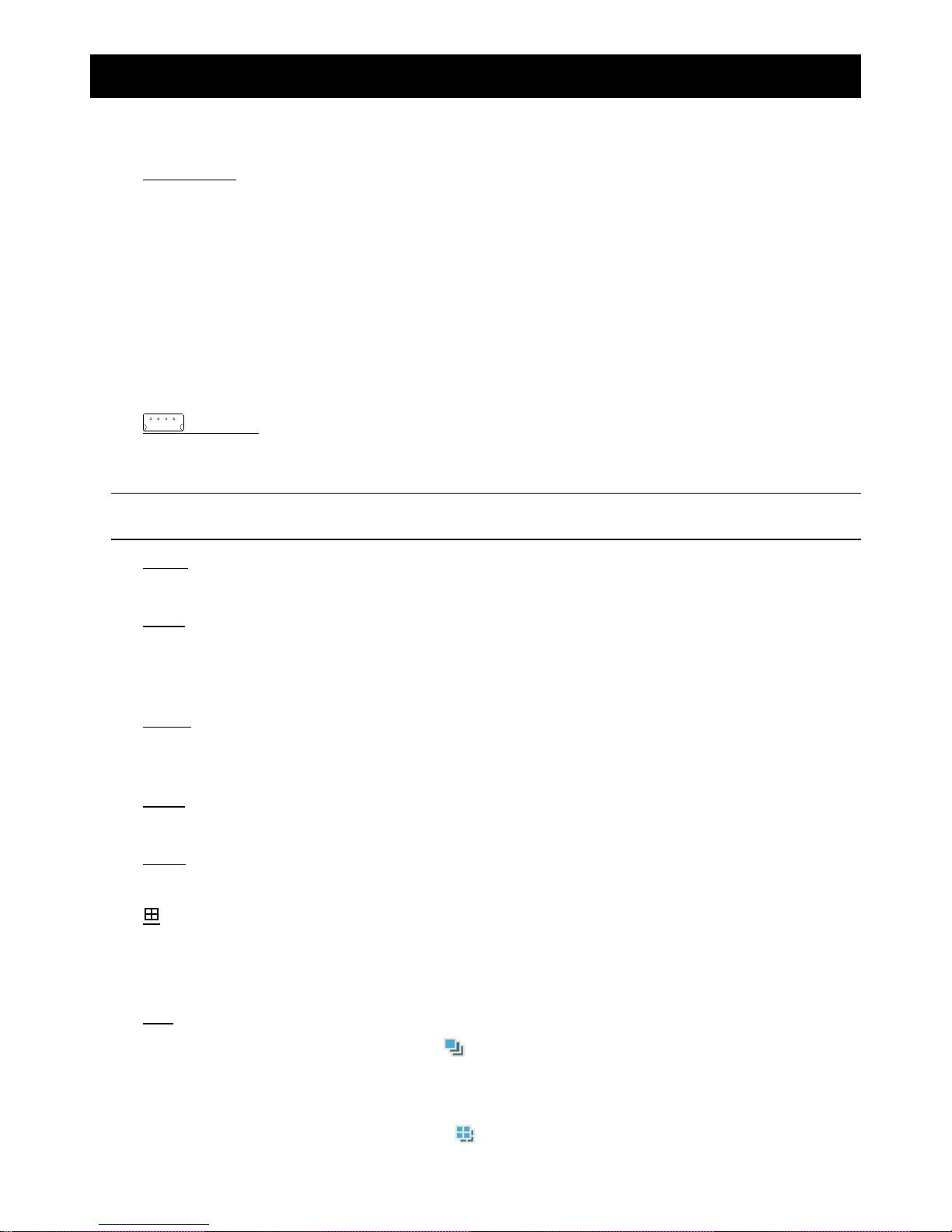
10) (Audio)
Use these two buttons to select the live or playback sound of the audio channels.
Icon “ ” means: Live audio of the 1st audio channel / Icon “ ” means: Playback audio of the 1st audio channel
Icon “
” means: Live audio of the 2nd audio channel / Icon “ ” means: Playback audio of the 2nd audio channel
Icon “
” means: Live audio of the 3rd audio channel / Icon “ ” means: Playback audio of the 3rd audio channel
Icon “
” means: Live audio of the 4th audio channel / Icon “ ” means: Playback audio of the 4th audio channel
Icon “
” means: The audio channel is not selected.
Note: If you want to make a video backup with audio, please connect audio cameras to the channels
which support the audio function
For 16CH & 8CH DVR, the audio channels are CH1, CH2, CH3 and CH4.
For 4CH DVR, the audio channels are CH1 and CH2.
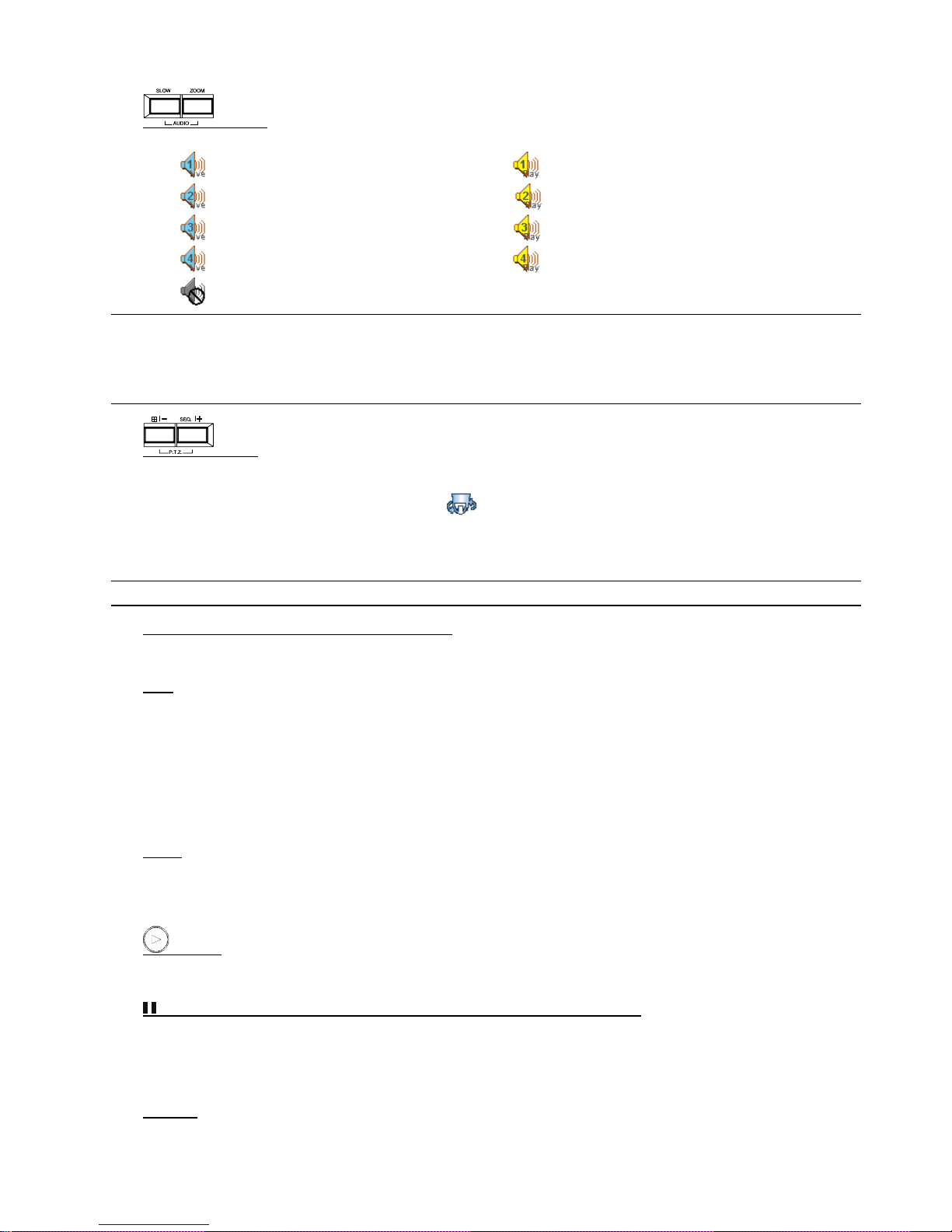
11) (PTZ)
Press these two buttons at the same time to enter / exit the PTZ control mode.
In the PTZ control mode (Indicated by the icon “ ”):
Zoom in: Press "+" button ; Zoom out: Press "-" button
Adjust PTZ angle: Press "UP”, “DOWN”, “LEFT” or “RIGHT" buttons
Note: For detailed PTZ camera control, please refer to “4.8 PTZ Camera Control” at page 19.
12) 1 ~ 16 (for 16CH) / 1~8 (for 8CH) / 1~4 (for 4CH)
Press one of the buttons to select the channel to display.
13) LIST
To quick search the recorded files by event list, press this button to show all types of the event lists.
ALARM: List the information of the alarm-trigger-recorded files.
MANUAL: List the information of the manual-recorded files. The DVR will save one recorded file once any recording setting is changed
MOTION: List the information of the motion-trigger-recorded files.
SYSTEM: List the information of the system-recorded files. The DVR system will save one recorded file every one hour.
TIMER: List the information of the timer-recorded files.
14) SNAP
Please connect a USB drive first and then press “SNAP” button to take a snapshot picture of the current image on
the monitor.
15) (PLAY)
Press this button to playback the recorded video.
16) (PAUSE/UP/ +), (REW/LEFT), (FF/RIGHT), ▓ (STOP/DOWN/ -)
Press one of these four buttons to move the cursor up/down/left/right.
Under the playback mode, press these buttons to pause / stop / fast rewind / fast forward the playback file.
Press ”UP/ +” or “DOWN/ -” button to change the setting in the menu.
17) POWER
Press “POWER” button long enough to turn on/off your DVR.
FRONT AND REAR PANELS
-6-
Note: Under the recording mode, please stop recording before turning off your DVR.
18) “MENU” + “ENTER” (KEY LOCK)
Press “MENU”+ “ENTER” button on the DVR front panel at the same time to lock keys.
Press any button on the DVR front panel and enter the DVR password to exit the key lock mode.
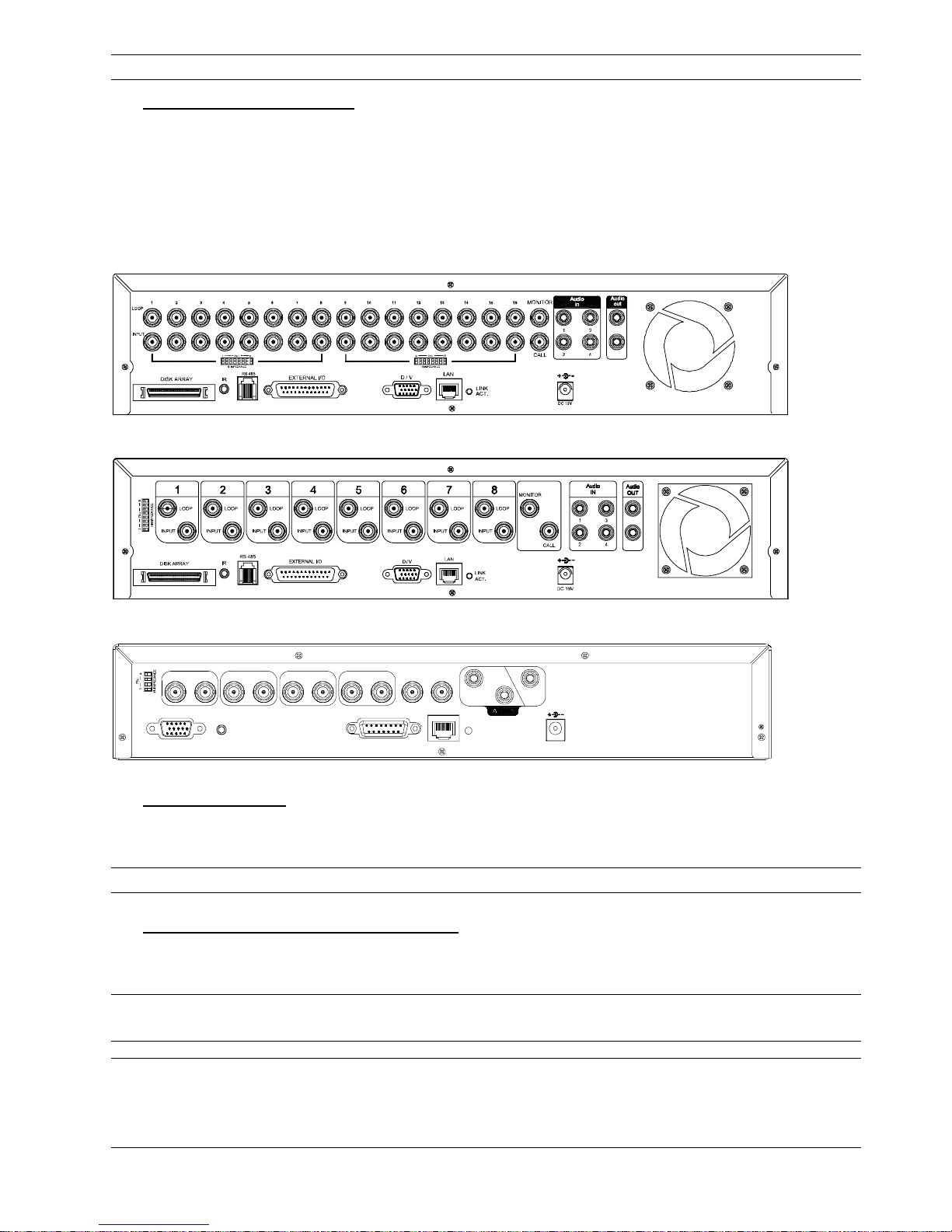
2.2 Rear Panel
‧ 16CH DVR model
‧ 8CH DVR model
‧ 4CH DVR model
1
LOOP
2
LOOP LOOP LOOP
3 4
1
MONIT O R
IN
OUT
2
VD
/
IR
CALL
LAN
LINK
ACT.
EXTERNAL I/O
DC 19V
INPUTINPUTINPUTINPUT
1) 75 / HI-IMPEDANCE
When using LOOP function, set the impedance switch at your DVR rear panel to HI-IMPEDANCE to decrease
interferences. Otherwise, switch to 75.
Note: The default setting is 75Ω.
2) LOOP / INPUT (1 ~ 16CH or 1 ~ 8CH or 1 ~ 4CH)
LOOP: Video output connector.
INPUT: Connect to video sources, such as cameras.
Note: The DVR will automatically detect the video system of the camera, please make sure that the
cameras are properly connected to the DVR and power-supplied before the DVR is turned on.
Note: If you want to make a video backup with audio, please connect audio cameras to the channels
which support the audio function.
For 16CH & 8CH DVR, the audio channels are CH1, CH2, CH3 and CH4.
For 4CH DVR, the audio channels are CH1 and CH2.

FRONT AND REAR PANELS
-7-
3) MONITOR
Connect to a CRT monitor for video output.
4) CALL
Connect to CALL monitor to show the channel display one by one.
When any alarm is triggered, CALL monitor will show the image of the triggered channel for a period of time.
5) Audio IN
Connect to audio sources, such as cameras equipped with the audio function.
For 16CH & 8CH DVR models: Four audio inputs (CH1, CH2, CH3 and CH4).
For 4CH DVR model: Two audio inputs (CH1 and CH2).
When users start recording, the audio input will also be recorded with corresponding video channel.
Note: The audio source connected to the “Audio 1” will be recorded with the video of the “CH1”.
The audio source connected to the “Audio 2” will be recorded with the video of the “CH2”.
The audio source connected to the “Audio 3” will be recorded with the video of the “CH3”.
The audio source connected to the “Audio 4” will be recorded with the video of the “CH4”.
6) Audio OUT
Connect to a monitor or speaker.
For 16CH & 8CH DVR models: Two audio outputs (Mono).
For 4CH DVR model: One audio output (Mono).
7) DISK ARRAY (Only for 16CH & 8CH)
Connect to an independent disk array for extended storage.
8) D/V
Connect to a VGA converter.
Note: For the connection of the VGA converter, do not use gender changer.
9) IR
Connect the IR receiver extension line for remote control.
10) RS-485 (Only for 16CH & 8CH)
Connect to external devices (such as PTZ camera) with RS485-A and RS485-B.
11) EXTERNAL I/O
Insert the supplied DSUB PIN to this port for connecting external devices (external alarm, PTZ camera, etc).
For detailed I/O port PIN configuration, please refer to “APPENDIX 1 PIN CONFIGURATION” at page 71.
12) LAN
Connect to Internet by LAN cable.
13) LINK ACT.
When your DVR is connected to the Internet, this LED will be on.
14) DC 19V
Connect to the supplied adapter.
15) FAN
Only 16CH and 8CH DVR have the fan equipment.
CONNECTIONS AND SETUP
-8-
3. CONNECTIONS AND SETUP (Take 16CH DVR as an example)
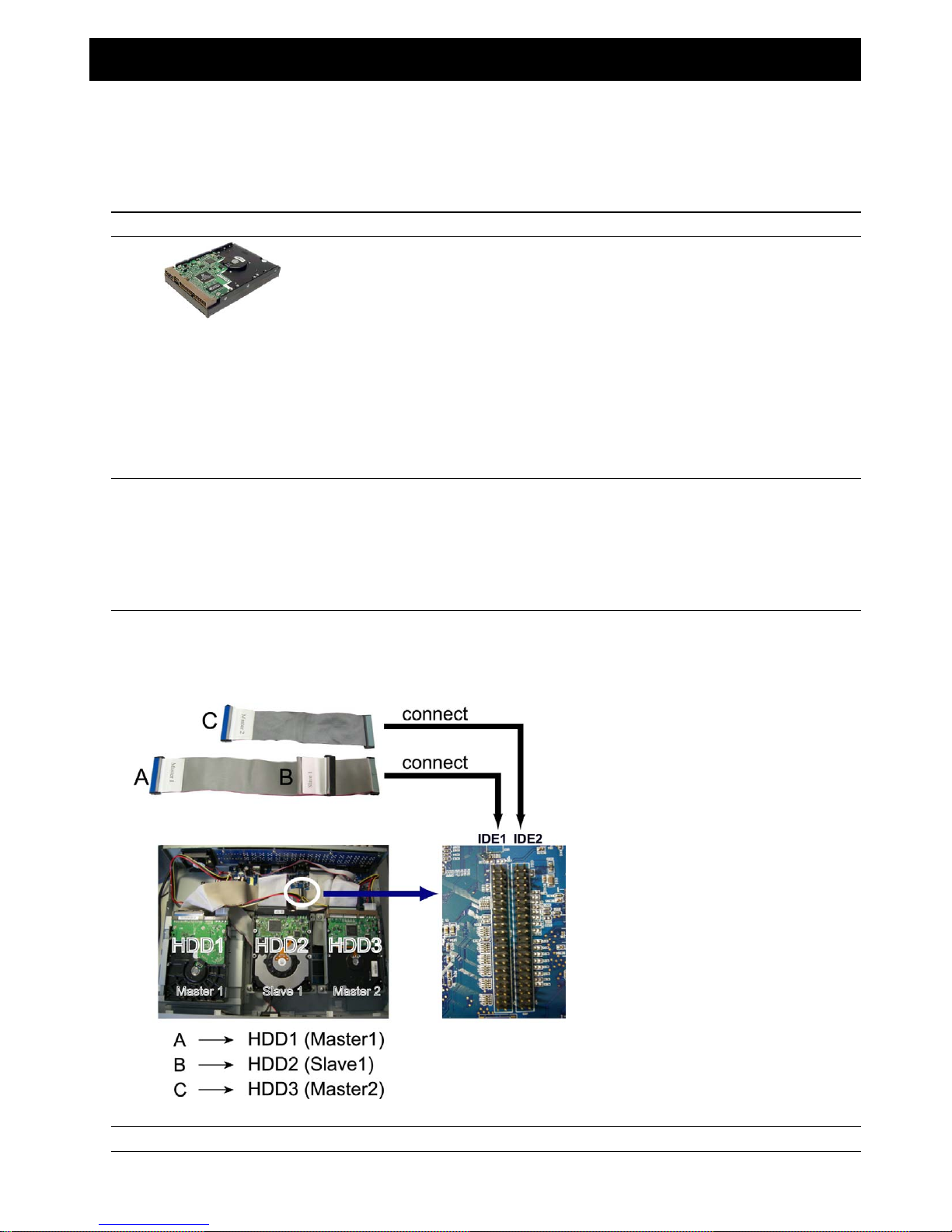
3.1 HDD Installation
‧ For 16CH & 8CH Models
Carefully follow the steps below to ensure correct HDD installation.
Note: The PCB side of the HDD must face upward, shown as the picture below.
Step 1: Loosen the screws on the upper cover and open the upper cover of the DVR
Step 2: Screw out the HDD bracket.
Step 3: Get suitable brand HDD and set the HDD mode (Master / Slave) according to the indication.
Step 4: After HDD mode setup, screw all the HDDs onto the HDD brackets, and replace the HDD brackets back to the
indicated position of the DVR base (Be sure to follow the indicated position shown as the picture below).
Note: For HDD mode setting rule and position, please refer to the following instructions:
* If you plan to install three HDDs, please set two HDDs to Master mode, and one HDD to Slave mode,
and place them to the exact position according to the indication.
* If you plan to install two HDDs, please set one HDD to Master mode and place it to the Master 1 position,
and set the other HDD to Slave mode and place it to the Slave 1 position.
* If you plan to install only one HDD, please set the HDD to Master mode and place it to the Master 1 position.
Step 5: Depending on which HDD you want to install, connect the HDD to the indicated power connector and IDE BUS
(make sure to align the HDD precisely for pin connection). For detailed connection, please follow and see the
illustration below:
NOTE: If you plan to install external disk array, please don’t install the HDD in the “HDD3”postion.
Step 6: Close the upper cover of the DVR, and fasten all the screws you loosened in Step 1.
CONNECTIONS AND SETUP
-9-
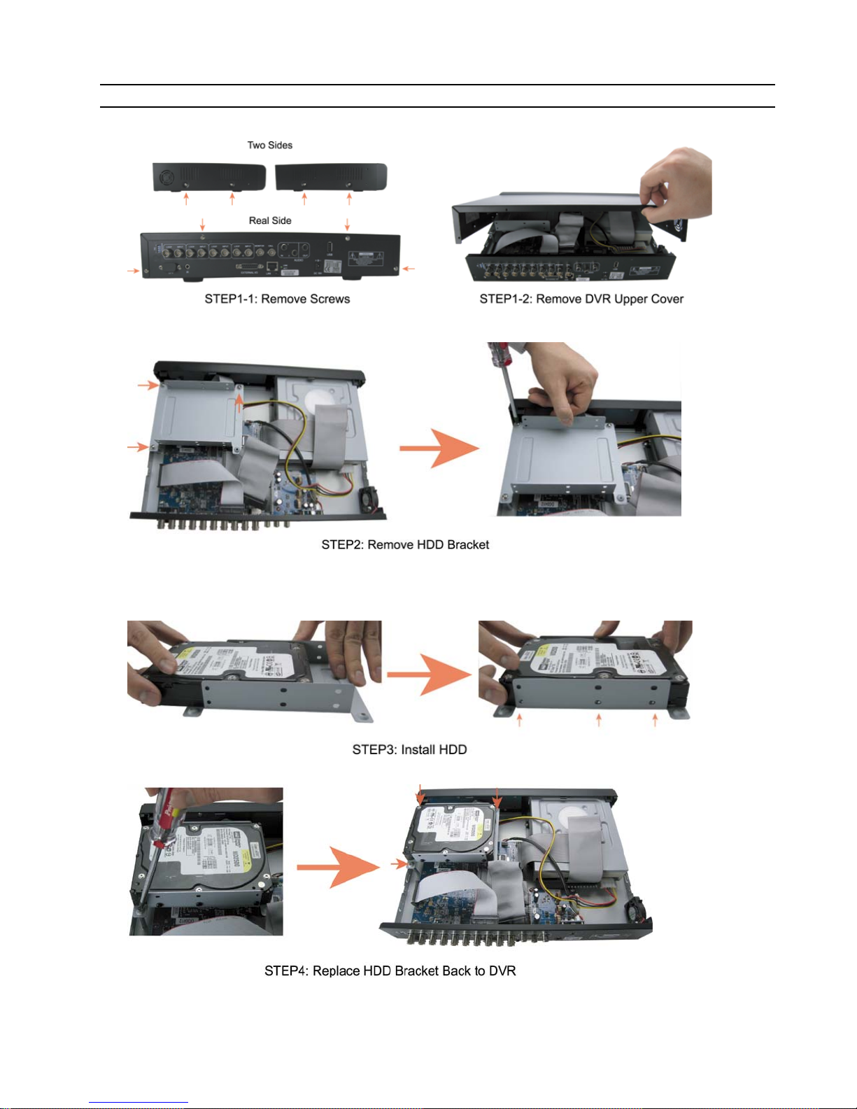
‧ For 4CH Model
Carefully follow the steps below to ensure correct HDD installation.
Note: The PCB side of the HDD must face upward, shown as the picture below.
Step 1: Loosen the screws on the upper cover and open the upper cover of the DVR.
Step 2: Remove the HDD bracket. For the position of the HDD bracket screws, please refer to the figure below.
Step 3: Get a suitable brand HDD and set the HDD mode to “Master”. Fasten the HDD to the HDD bracket, two screws for
each side. There are three screw holes per side on the bracket, and you can choose two of them to secure the
HDD.
Step 4: Screw the HDD bracket back to the DVR base.
CONNECTIONS AND SETUP
-10-
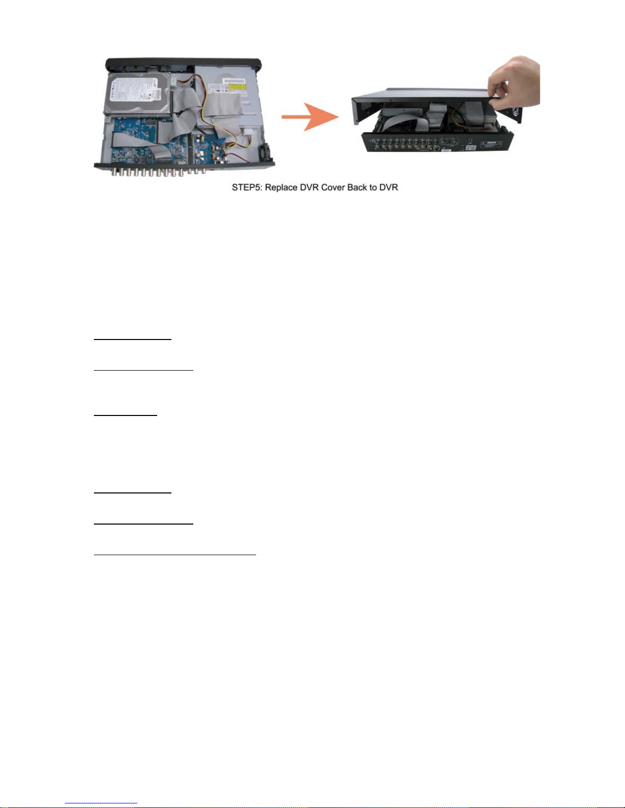
Step 5: Connect the HDD to the power connector and IDE BUS (make sure to align the HDD precisely for pin connection).
Then, close the upper cover of the DVR and fasten all the screws you loosened in the step 1.
3.2 Camera Connection
The cameras must be connected and power-supplied before the DVR is turned on. Connect the camera with the
indicated power supply. And then connect the camera video output to the DVR video input port with a coaxial cable or
RCA lines with BNC connectors (The DVR will automatically detect the video system of the camera).
3.2.1 Normal Camera Connection
1) Power connection:
Connect the camera with indicated power supply.
2) Video cable connection:
Connect the camera video output to the DVR video input port with a coaxial cable or RCA line with BNC
connector.
3) Camera Setup:
For detailed camera title, ID, protocol and baud rate setup, please refer to “7.1.7 Remote” at page 33.
3.2.2 PTZ Camera Connection
4) Power connection:
Connect the PTZ camera with indicated power supply.
5) Video cable connection:
Connect the PTZ camera video output to the DVR video input with a coaxial cable / RCA line and BNC connector.
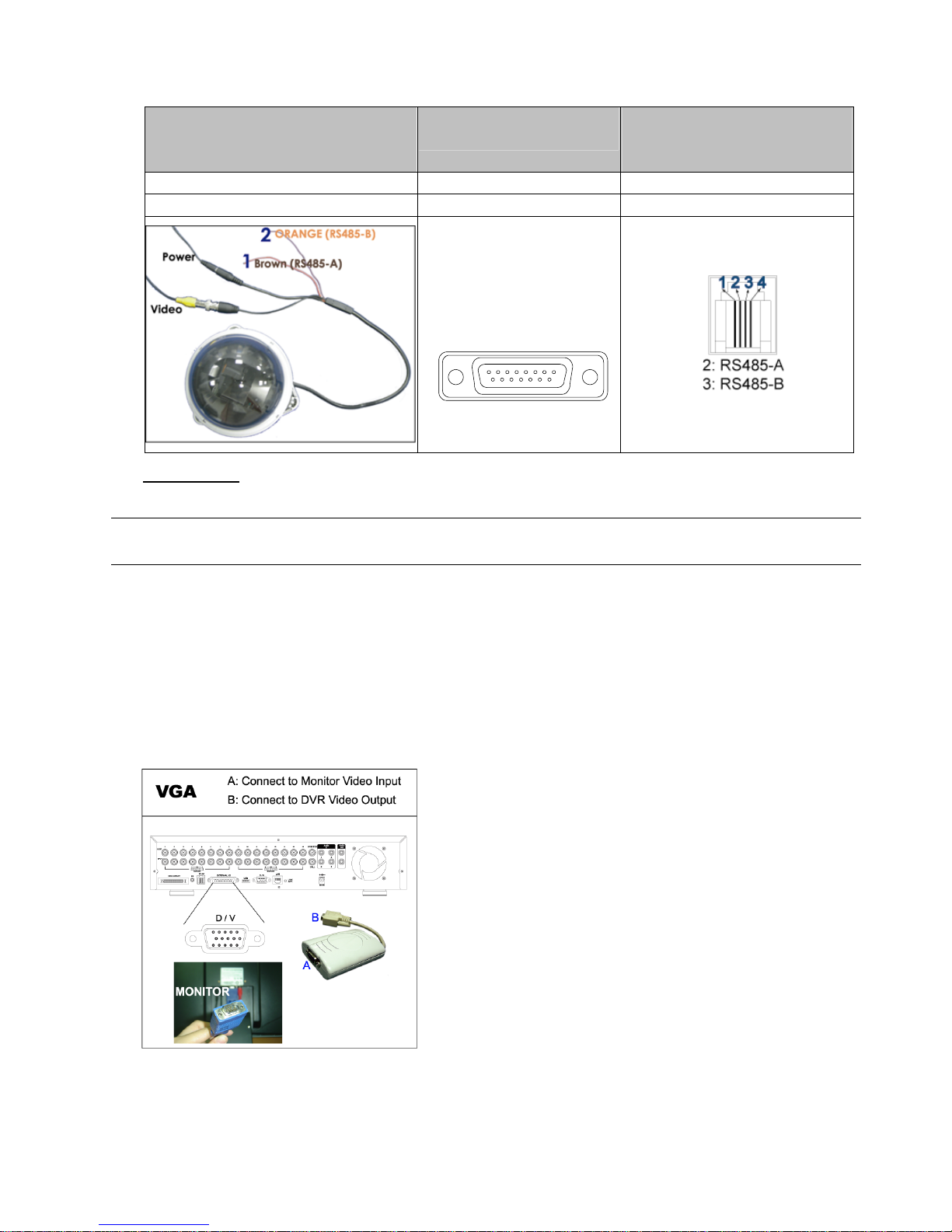
6) RS485-A & RS485-B wires connection:
For 4CH DVR Model:
Solder the RS485-A (brown) and RS485-B (orange) wires of the PTZ camera to the corresponding pins on the
solder side of the 15 PIN D-Sub connector (see the figure below). To protect the naked wires, use the insulation
tape to cover on the twisted wires.
CONNECTIONS AND SETUP
-11-
7) For 16CH & 8CH DVR Model:
Insert the RS485-A (brown) and RS485-B (orange) wires of the PTZ camera to the corresponding pins on the
“RS485” port of the DVR rear panel (see the figure below).
PTZ Camera –
RS485-A and RS485-B wires of the PTZ
camera
For 4CH DVR –
15 PIN D-Sub Connector
For 16CH & 8CH DVR –
RS-485 Port on the DVR Rear
Panel
RS485-A: Brown wire RS485-A: PIN 11 RS485-A: PIN 2
RS485-B: Orange wire RS485-B: PIN 10 RS485-B: PIN 3
Solder Side of
15-pin D-Sub connector
RS485-A: PIN11; RS485-B: PIN10
1
912131415
16 17
2345678
1011
8) Camera Setup:
For detailed camera title, ID, protocol and baud rate setup, please refer to “7.1.7 Remote” at page 33.
Note: For connect the PTZ camera to the DVR with a keyboard controller, please refer to “3.3.3 Connect
PTZ Camera and DVR with Keyboard Controller” at page 12.
3.3 External Device Connections (Optional)
3.3.1 VGA Converter Connection
This optional peripheral (VGA Converter) allows your DVR to have VGA output function. For the connection
method, please refer to the following figure as an example (do not use gender changer). For detailed connection,
please refer to your VGA converter manual.
CONNECTIONS AND SETUP
-12-
3.3.2 Independent Disk Array Connection
For the connected IDA to be correctly detected by your DVR, please don’t install HDD in the “HDD3” position. For
connection details, please refer to "3.1 HDD Installation" at page 8.
1) Install HDDs:
Install HDDs in the IDA. Please set the HDD to “Master” mode (do not use “Slave” mode). After all HDDs are
installed, please lock the HDD tray by using the HDD key supplied in the IDA package.
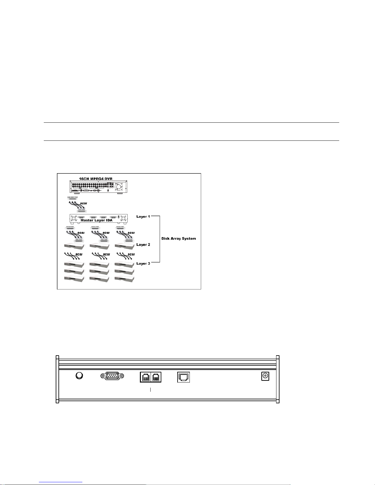
2) Connect all IDA with SCSI cables (hub IDA only):
Connect from one of the three “DEVICE PORT” at one IDA rear panel to the host port of another disk array.
One IDA (as the master layer) can connect up to 3 IDA as the second layer, and each IDA in the second layer can
respectively connect up to 3 IDA as the third layer. Please refer to the illustration below for details.
Note: In order to accurately detect all the connected disk arrays, please make sure to turn on the power of all the
disk arrays after the connection is completed. The maximum layer number is 3, totally 13 IDA.
3) Connect the master IDA to your DVR with a SCSI Cable (IDE interface):
Connect the host port of the master IDA to the “DISK ARRAY” port of your DVR. Please refer to the illustration
below for details.
3.3.3 Connect PTZ Camera and DVR with Keyboard Controller
This optional peripheral (keyboard controller) allows your DVR to have accurate control of the pan / tilt / zoom
movement for a PTZ camera with the convenient 3D joystick and functional keypad design. The following connection
illustration is an example. For detailed connection and operation, please refer to your keyboard controller manual.
Rear panel of the keyboard controller:
DC 12VAUDIO LANEXTERNAL I/O DVR P.T.Z
CONNECTIONS AND SETUP
-13-
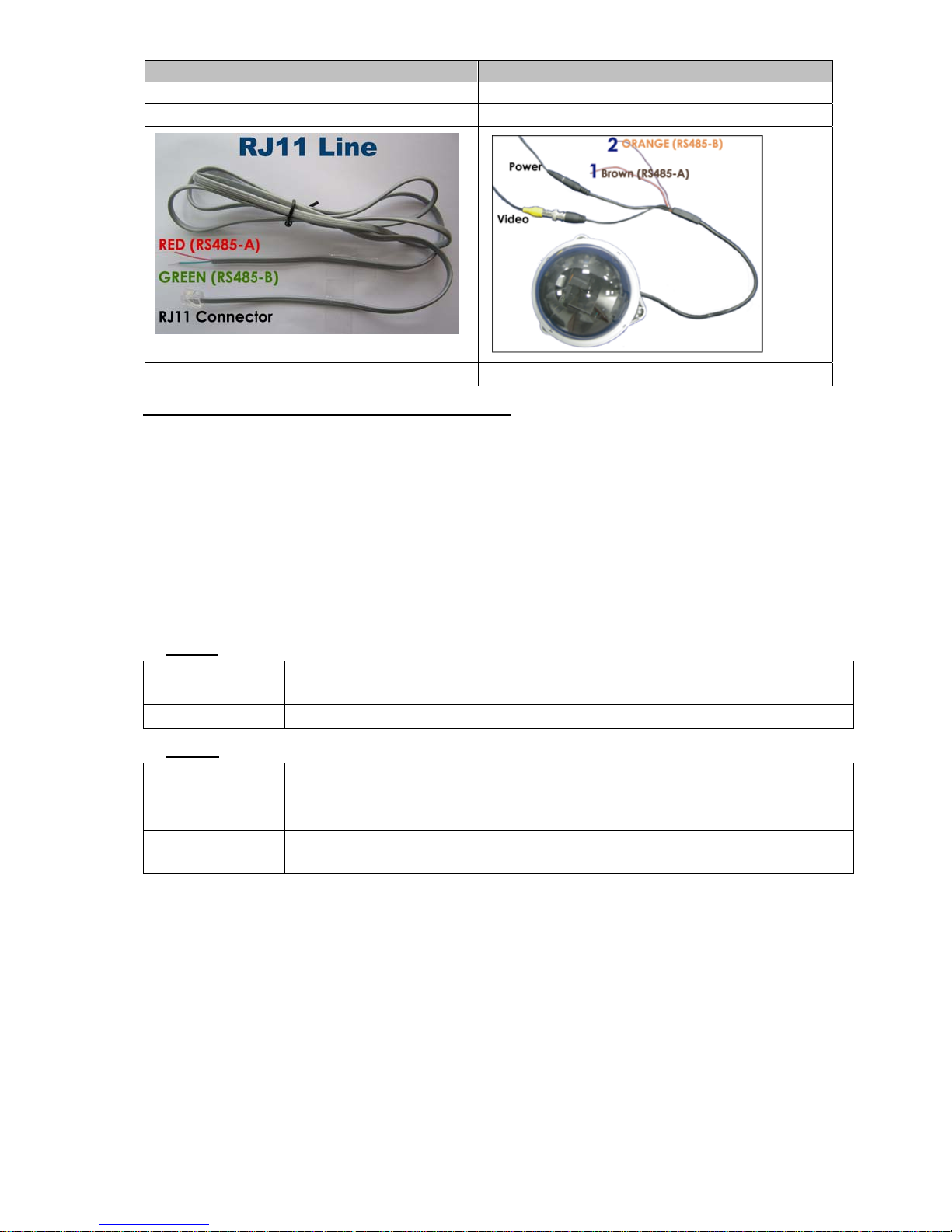
● Connect PTZ to Keyboard controller with RJ11 line :
RJ11 Line RS485-A and RS485-B wires of the PTZ camera
RS485-A: Red wire RS485-A: Brown wire
RS485-B: Green wire RS485-B: Orange wire
The RJ11 line is not supplied in the sales package. Example of RS485-A and RS485-B wires of the PTZ camera.
1) Get a RJ11 line with the proper length to your connection.
Different RJ11 connector may have different line layout, so the connection might be different. If you cannot control
the PTZ camera after connection, please reverse the RJ11 line connection with the PTZ camera.
2) Remove one end of the insulating coating of the RJ11 line to find the RS485-A and the RS485-B wires, and
remove the insulating coating to reveal the naked wires for further connection.
3) Twist the RS485-A (red) and RS485-B (green) wires of the RJ11 line to the RS485-A (brown) and RS485-B
(orange) wires of the PTZ camera (see the figure above). To protect the naked wires, use the insulation tape to
cover on the twisted wires.
4) Connect the RJ11 connector to the “PTZ” port on the rear panel of the keyboard controller.
5) Press “F1” key on the keyboard controller, and go to “System” and “Camera” menu to make related settings.
‧ System
MODE : To select the mode, press “F1” key on the keyboard controller. Go to “System” →
“MODE” and select M-1 (For the case of one DVR and one camera connection).
NET IP : Check if this product is under the same domain as the connected PTZ camera.
‧ Camera
RATE : Check and select the baud rate the same as the connected PTZ camera is used.
MODE : Choose the proper camera protocol depending on the camera type, AVP321 / AVP311 /
PELCO (PELCO-D).
ID : Assign an exclusive ID number. This ID is important for the keyboard controller to
identity the camera you want to control.
CONNECTIONS AND SETUP
-14-
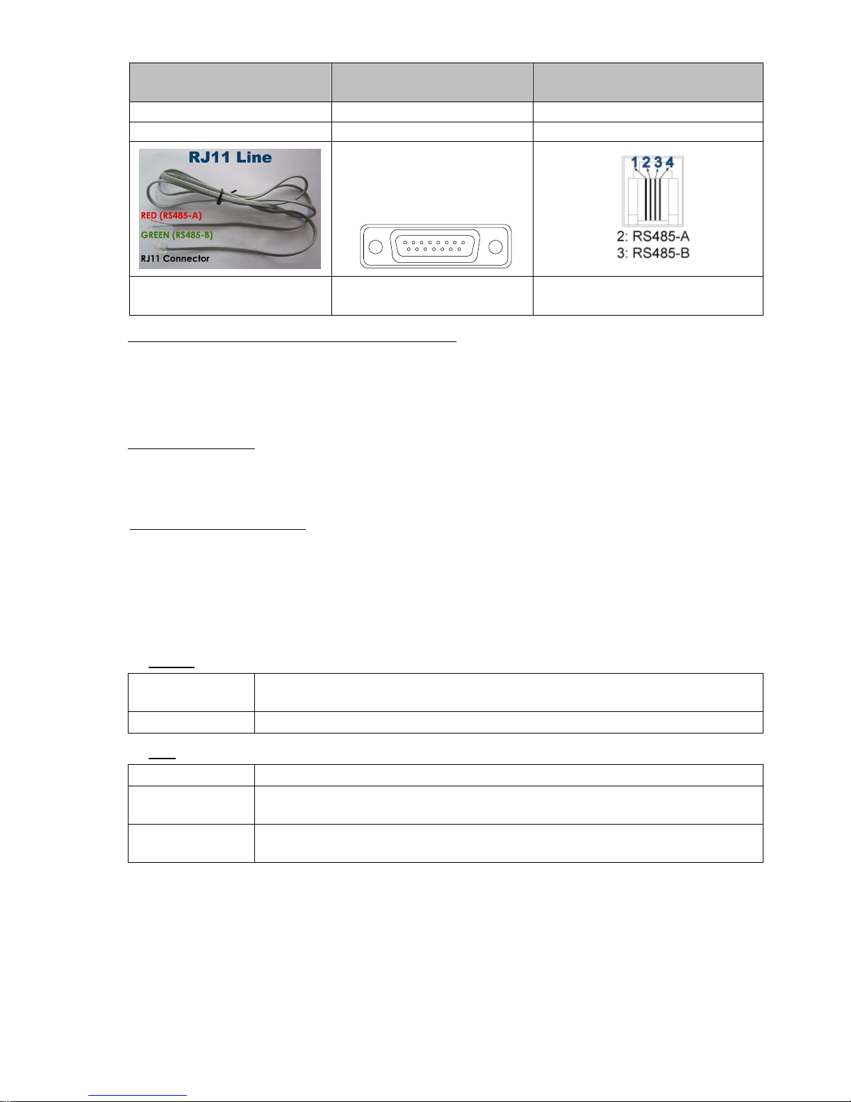
● Connect DVR to Keyboard controller with RJ11 line and D-Sub connector or RS-485 Port:
RJ11 Line
For 4CH DVR –
15 PIN D-Sub Connector
For 16CH & 8CH DVR –
RS-485 Port on the DVR Rear Panel
RS485-A: Red wire RS485-A: PIN 11 RS485-A: PIN 2
RS485-B: Green wire RS485-B: PIN 10 RS485-B: PIN 3
Solder Side of
15-pin D-Sub connector
RS485-A: PIN11; RS485-B: PIN10
1
912131415
16 17
2345678
1011
The RJ11 line is not supplied in the sales
package.
D-Sub connector is supplied with the
DVR package.
Example of RS485 port on the DVR rear
panel.
1) Get a RJ11 line with the proper length to your connection.
Different RJ11 connector may have different line layout, so the connection might be different. If you cannot control
the DVR after connection, please reverse the RJ11 line connection with the DVR.
2) Remove one end of the insulating coating of the RJ11 line to find the RS485-A and the RS485-B wires, and
remove the insulating coating to reveal the naked wires for further connection.
3) For 4CH DVR Model:
Solder the RS485-A (red) and RS485-B (green) wires of the RJ11 line to the corresponding pins on the
solder side of the 15 PIN D-Sub connector (see the figure above). To protect the naked wires, use the
insulation tape to cover on the twisted wires.
For 16CH & 8CH DVR Model:
Insert the RS485-A (red) and RS485-B (green) wires of the RJ11 line to the corresponding pins on the
“RS485” port of the DVR rear panel (see the figure above).
4) Insert the D-Sub connector to the DVR’s external I/O port. And connect the RJ11 connector to the “DVR” port
on the rear panel of the keyboard controller.
Press “F1” key on the keyboard controller, and go to “System” and “DVR” menu to make related settings.
‧ System
MODE : To select the mode, press “F1” key on the keyboard controller. Go to “System” →
“MODE” and select M-1 (For the case of one DVR and one camera connection).
NET IP : Check if this product is under the same domain as the DVR.
‧ DVR
RATE : Check and select the baud rate the same as the DVR is used.
MODE : Choose the proper DVR protocol depending on the DVR type, DVR-16 (16CH) / DVR-8
(8CH) / DVR-4 (4CH).
ID : Assign an exclusive ID number. This ID is important for the keyboard controller to
identity the DVR you want to control.
CONNECTIONS AND SETUP
-15-
3.3 Power Setup
This device should be operated only with the type of power source indicated on the manufacturer’s label. Connect
the indicated AC power cord to the power adapter, and plug into an electrical outlet. Power LED will be on as blue. It
takes approximately 10 to 15 seconds to boot the system.
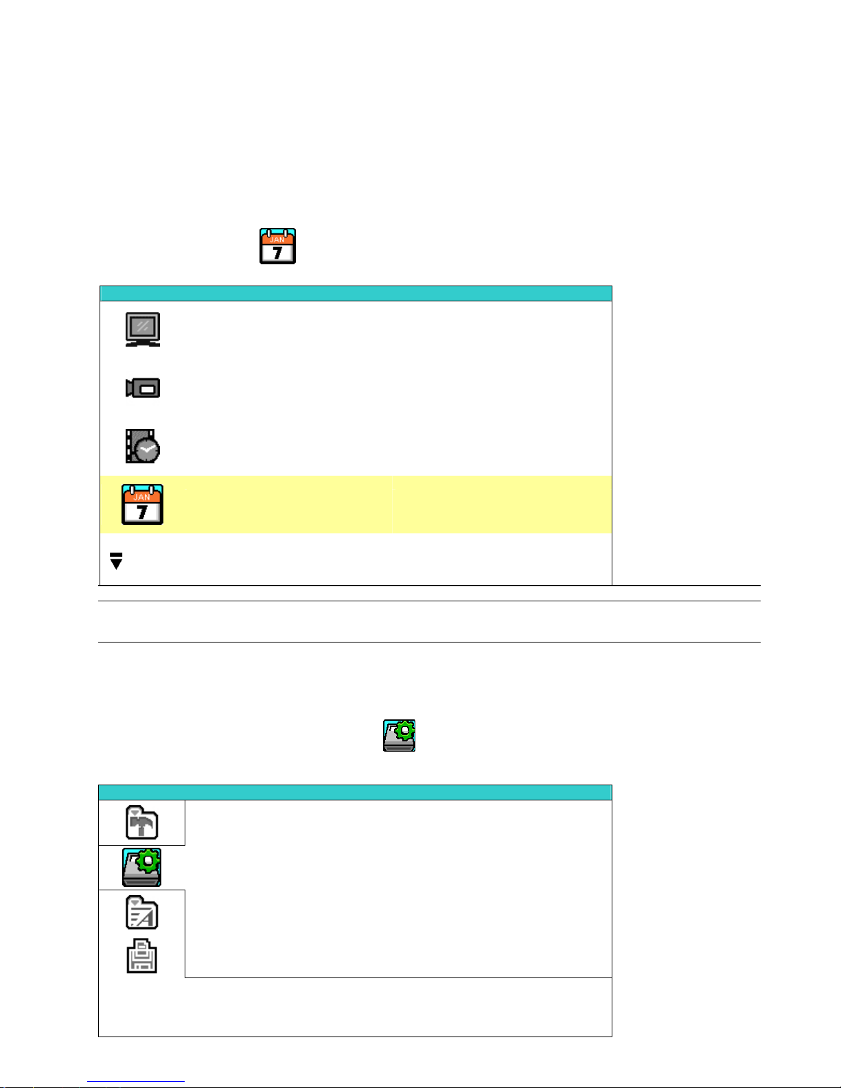
3.4 Date and Time Setting
Before operating your DVR, please set the date and time on your DVR first.
Press “MENU” button and enter the password to go to the quick-start menu list. The default admin password is 0000.
Move the cursor to the icon “ ” (DATE) and you can set the date / time / daylight saving in this menu list.
QUICK START
CHANNEL TITLE ON
EVENT STATUS ON
IMAGE SIZE CIF
QUALITY BEST
IMAGE PER SECOND 120
RECORD TIMER OFF
DETECTION TIMER OFF
DATE 2007 / OCT / 11 09 : 00 : 00
FORMAT Y / M / D
DAYLIGHT SAVING OFF
ADVANCE uv SELECT s BACK t NEXT ENTER
Note: If the time and date settings return to their default values after the DVR is rebooted, please charge
the DVR for at least 24-48 straight hours. Please contact your local retailer if the situation still
occurs.
3.5 Password Setting
Press “MENU” button and enter the password to go to the quick-start menu list. And then move the cursor to
“ADVANCE” to enter the advanced setting menu.
In the “ADVANCE” menu, move the cursor to “ ” (SYSTEM INFO). Select “PASSWORD” and press “ENTER”
button to enter the submenu to set the password (four digits). The default admin password is 0000.
SYSTEM INFO
SERIAL TYPE RS485
BAUD RATE 2400
HOST ID 0
PASSWORD XXXX
RESET DEFAULT RESET
CLEAR HDD HDD-MASTER-1
UPGRADE START
AUTO KEYLOCK (SEC) 30
LANGUAGE ENGLISH
VIDEO FORMAT NTSC
VERSION 1143-1011-1021-1013-M1-6C1B
PLEASE CONSULT YOUR INSTALLER FOR ADVANCE SETTINGS
uv SELECT s BACK t NEXT ENTER
BASIC OPERATION
-16-
4. BASIC OPERATION (Take 16CH DVR as an example)
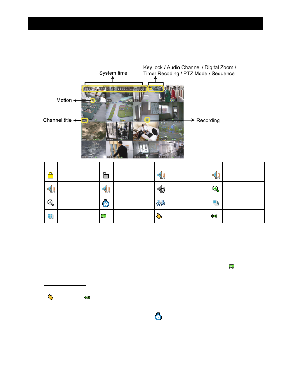
4.1 Live Page
In this live page of the DVR, you can see the live viewing of 1- / 4- / 9- / 16-cut screen.
Icon Function Icon Function Icon Function Icon Function
Key lock Key unlock
1st live audio
channel
2nd live audio
channel
3rd live audio
channel
4th live audio
channel
Audio channel
unselected
Digital zoom mode
Digital zoom
unselected
Timer recording
PTZ control mode
Full screen
sequence mode
Quad screen
sequence mode
Recording
Motion
Alarm
4.2 Recording
When the recording and the pre-alarm function are activated, this device will overwrite 8GB data from the oldest
for continuous recording without notice.
1) Continuous Recording Icon
When the DVR is properly connected with camera and HDD is installed, you can see the icon “ ” (recording)
on the screen.
2) Event Recording Icon
When the motion / alarm detection is activated, once motion or external alarm happens, you will see the icon
“ ” (motion) or “ ” (external alarm) on the screen.
3) Timer Recording Icon
When the timer record is activated, you will see the icon “ ” (timer) on the screen.
Note: The audio source connected to the “Audio 1” will be recorded with the video of the “CH1”.
The audio source connected to the “Audio 2” will be recorded with the video of the “CH2”.
The audio source connected to the “Audio 3” will be recorded with the video of the “CH3”.
The audio source connected to the “Audio 4” will be recorded with the video of the “CH4”.
BASIC OPERATION
-17-
4.3 Playback
Press the “ ” (PLAY) button on the DVR control panel, and the device will playback the latest recorded video.
Note: There must be at least 8192 images of recorded data for playback to work properly. If not, the
device will stop playback. For example, if the IPS is set to 30, the recording time should be at least
273 seconds (8192 images / 30 IPS) for the playback to work properly.
1) Fast Forward () / Fast Rewind ()
You can increase the speed for fast forward and rewind on this device. In the playback mode:
Press ““ once to get 4X speed forward and press twice to get 8X speed, etc. And the maximum speed is 32X.
Press ““ once to get 4X speed rewind and press twice to get 8X speed, etc. And the maximum speed is 32X.
Note: During playback, the image size of the recording (Frame, Field or CIF) will be shown on the screen.
2) Pause ( ) / Image Jog
Press “ ” button to pause the playback.
In the Pause mode:
Press “” button once to get one frame forward.
Press “” button once to get one frame rewind.
3) Stop (▓)
Pressing “STOP” button under playback mode, the screen of this device will return to live monitoring mode.
4) Slow Playback
Press “SLOW” button to get 1/4X speed playback and press twice to get 1/8X speed playback.
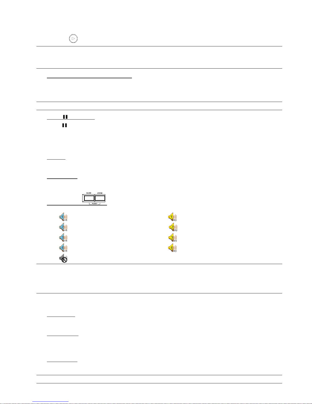
5) Audio Playback ( )
Use these two buttons to select the live or playback sound of the audio channels.
Icon “
” means: Live audio of the 1st audio channel / Icon “ ” means: Playback audio of the 1st audio channel
Icon “
” means: Live audio of the 2nd audio channel / Icon “ ” means: Playback audio of the 2nd audio channel
Icon “
” means: Live audio of the 3rd audio channel / Icon “ ” means: Playback audio of the 3rd audio channel
Icon “
” means: Live audio of the 4th audio channel / Icon “ ” means: Playback audio of the 4th audio channel
Icon “
” means: The audio channel is not selected.
Note: If you want to make a video backup with audio, please connect audio cameras to the channels
which support the audio function
For 16CH & 8CH DVR, the audio channels are CH1, CH2, CH3 and CH4.
For 4CH DVR, the audio channels are CH1 and CH2.
4.4 Key Lock and Unlock
1) Key Lock On:
Press “MENU”+ “ENTER” button on the DVR front panel at the same time to lock keys.
2) Auto Key Lock:
Set the time-out after which the key lock function is activated (Never / 10 SEC / 30 SEC / 60 SEC). Please refer to
“7.2 System Info” at page 34.
3) Key Lock Off:
Enter the DVR password to exit “Key Lock” mode.
Note: For the password setting, please refer to “3.5 Password Setting” at page 15.
BASIC OPERATION
-18-
4.5 Upgrade
Note: Do not disconnect the power of your DVR while the upgrade process is in progress, or the DVR
functions may not work properly or be unable to use.
‧ Firmware / Multilanguage OSD Upgrade
1) Use USB to upgrade firmware or OSD:
Step 1. Format the USB memory device as FAT32 format first.
Step 2. Get the upgrade files from your distributor and save the upgrade files in your USB flash device (do not
change the file name).
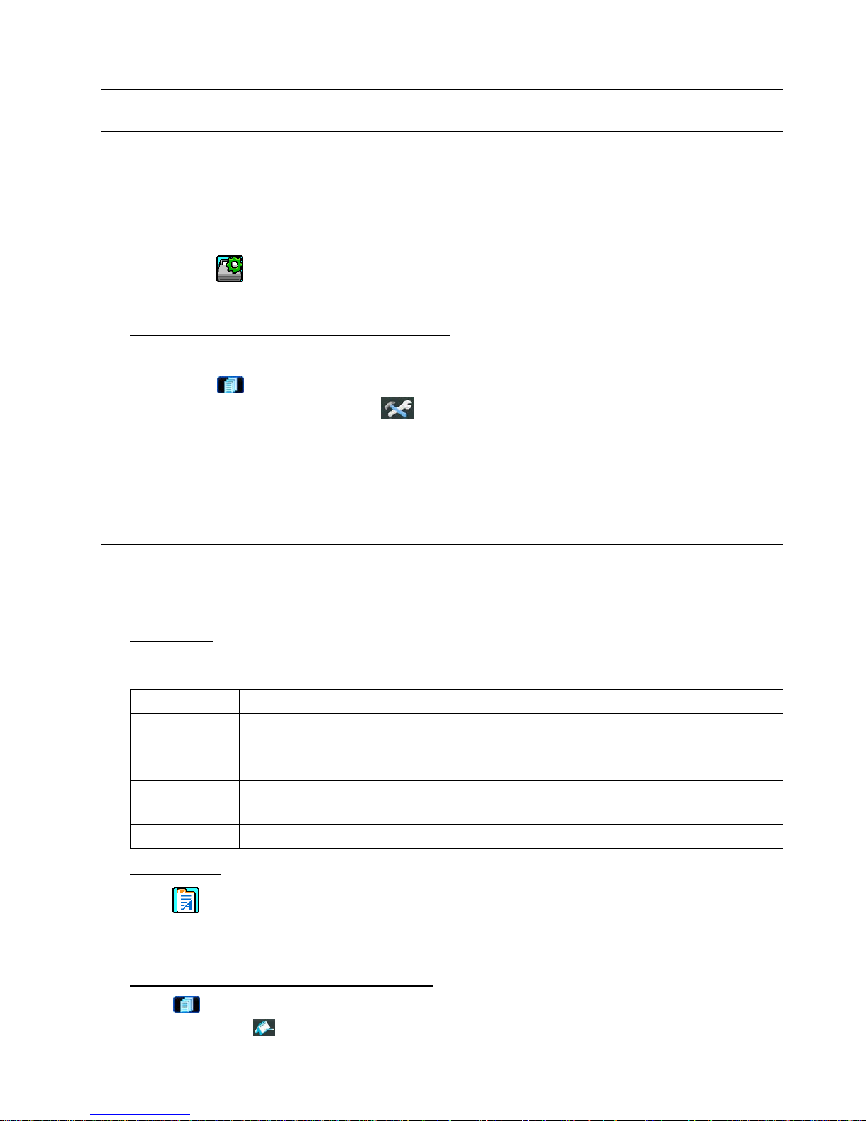
Step 3. In the “ ” (SYSTEM INFO) menu, move the cursor to “UPGRADE”, and press “ENTER” button.
Step 4. Select “YES”, and press “ENTER” button again to confirm upgrade.
2) Use AP software to remotely upgrade firmware or OSD:
Step 1. Save the upgrade files at your PC (do not change the file name) and then login to the AP software.
Step 2. Press “ ” (Miscellaneous Control) button to show the miscellaneous control panel. In the
miscellaneous control panel, press “ ” (Tools) button on the miscellaneous control panel to enter the
AP upgrade window.
Step 3. Enter the user name, password, IP address and port number of the DVR.
Step 4. Press “Firmware” or “Language” tab as needed, and press “Add” to select the firmware or OSD files to
upgrade.
Step 5. Press “Update Firmware” or “Update Language” button to start the upgrade.
Note: For remote upgrade details, please see “Tools” at page 59.
4.6 Search
1) Search by List
Press “LIST” button on the DVR control panel to show the list for all types of the recorded files. Choose the list
you want to view and press “ENTER” button to start playback.
ALARM List the information of the alarm-trigger-recorded files.
MANUAL List the information of the manual-recorded files. The DVR will save one recorded file once
any recording setting is changed
MOTION List the information of the motion-trigger-recorded files.
SYSTEM List the information of the system-recorded files. The DVR system will save one recorded
file every one hour.
TIMER List the information of the timer-recorded files.
2) Search by Time
In the “ ” (EVENT LOG) menu list, move the cursor to “QUICK SEARCH”, and press “ENTER” button to enter
the quick search menu. You can search any specific events by time (Year / Month / Day / Hour / Min) and directly
play the file you find.
3) Search the Record Event by Log on the AP Software
Press “ ” (Miscellaneous Control) button to show the miscellaneous control panel. In the miscellaneous
control panel, press “ ” button to enter the “Status List” page. In this log view page, you can see the list of three
different types of recording (User / Motion / Alarm) and press “Play” button to directly playback the file.
BASIC OPERATION
-19-
4.7 Audio Backup and Playback
The DVR only has several channels that support audio backup. If you want to backup images with audio, please
connect the cameras to the correct channels. For detailed camera connection, please refer to “3.2 Camera
Connection” at page 10. For 16CH and 8CH model, the audio channels are CH1 – CH4. For 4CH model, the audio
channels are CH1 – CH2. For detailed backup instruction, please refer to “7.4.2 DISK BACKUP (Optional)” at page 36.
To select live or playback sounds of the audio channels, please press these two buttons “ ” on the DVR
front panel at the same time. For detailed playback instructions, please refer to “4.3 Playback” at page 17. For detailed
playback instructions on the remote side, please refer to “Playback” at page 41.
4.8 PTZ Camera Control
Please connect the PTZ camera with the DVR and setup the required camera settings first. For the PTZ camera
connection, please refer to “3.2.2 PTZ Camera Connection” at page 10, or refer to “3.3.3 Connect PTZ Camera and
DVR with Keyboard Controller” at page 12. For the PTZ camera ID, protocol, baud rate setting (at the DVR menu),
please refer to “7.1.7 Remote” at page 33.
1) PTZ control at DVR side:
Press the two buttons “ ” on the DVR front panel at the same time to enter / exit the PTZ control mode.
In the PTZ control mode:
Zoom in: Press "+" button ; Zoom out: Press "-" button
Adjust PTZ angle: Press "UP”, “DOWN”, “LEFT” or “RIGHT" buttons
2) PTZ control at keyboard controller side:
Press this key to enter the PTZ camera control mode. In the control mode of the PTZ
camera, the LED light of the PTZ camera icon on the controller will be on.
KEYS OPERATION
Press this key to access the main menu of the PTZ camera.
Use the up or down key to position the cursor beside the selection / make selection.
Press the right key, the sub-menu shows up.
Press the left key, go the upper layer of the menu list.
Use the enter key to confirm the setting / Enter the sub-menu
FUN.1
Press this key to configure the setting of the PTZ camera on the controller LCD display.
In the setting menu, use the navigation keys to select and modify the setting.
SET.
This key is saved for future functions.
SEQ.
Press this key to start sequence function. Press it again to exit the sequence mode.
GOTO
Press this key to go to the preset point
- FOCUS +
Adjust the focus of the PTZ camera.
/
Press these keys to zoom out / zoom in the PTZ camera.
TRACK
Press this key to start auto-tracking function and press it again to exit.
STOP
NA
- / +
NA
0 ~ 9
Use this number pad to enter the camera ID, channel number and password, etc.
ESC
Ignore the setting and exit.
Confirm the setting
Use the joystick to control the PTZ camera to move up / down / left / right.
Turn the joystick clockwise to zoom in. Turn the joystick counter-clockwise to zoom out.
MAIN MENU
-20-
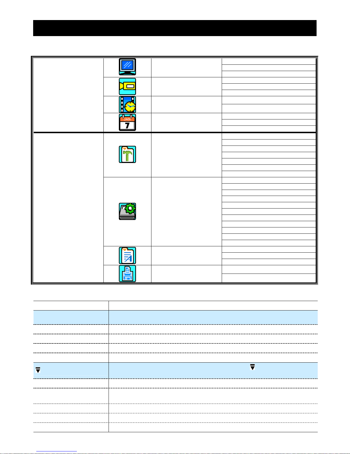
5. MAIN MENU
5.1 Menu Configuration
CHANNEL TITLE
EVENT STATUS
STATUS
IMAGE SIZE
QUALITY
RECORD
IMAGE PER SECOND
RECORD TIMER
TIMER
DETECTION TIMER
DATE
FORMAT
QUICK START MENU
DATE
DAYLIGHT SAVING
CAMERA
DETECTION
ALERT
NETWORK
DISPLAY
RECORD
ADVANCE CONFIG
REMOTE
SERIAL TYPE
BAUD RATE
HOST ID
PASSWORD
RESET DEFAULT
CLEAR HDD
UPGRADE
AUTO KEYLOCK (SEC)
LANGUAGE
VIDEO FORMAT
SYSTEM CONFIG
VERSION
QUICK SEARCH
HDD INFO
EVENT LOG
EVENT LOG
USB BACKUP
ADVANCED MENU
BACKUP
DISK BACKUP
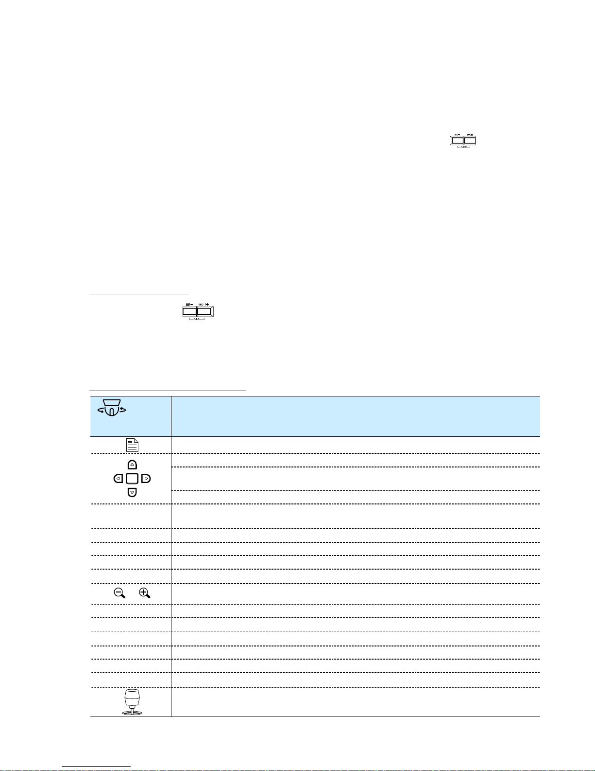
5.2 Menu Operation Instruction
ITEM FUNCTION
QUICK START MENU: View & change the settings of the quick start menu items
MENU Enter / exit the quick start menu
UP, DOWN Make the selection / Change the setting
LEFT, RIGHT Go to the upper layer or sub-layer / Make the selection
ENTER Confirm the password entering
ADVANCED MENU:
In the quick start menu, move the cursor to the icon “ ” and press “DOWN”
button to enter the advanced setting menu.
ENTER Go to the sub-layer of the advanced menu
MENU
Under the sub-layer of the advanced setting menu, use this button to confirm the
settings and go back to the upper layer.
t NEXT Move the cursor to this item and press “ENTER” button to go the next page.
s BACK Move the cursor to this item and press “ENTER” button to go the previous page.
Other operations in the advanced menu are the same as in the quick start menu.
QUICK START MENU
-21-
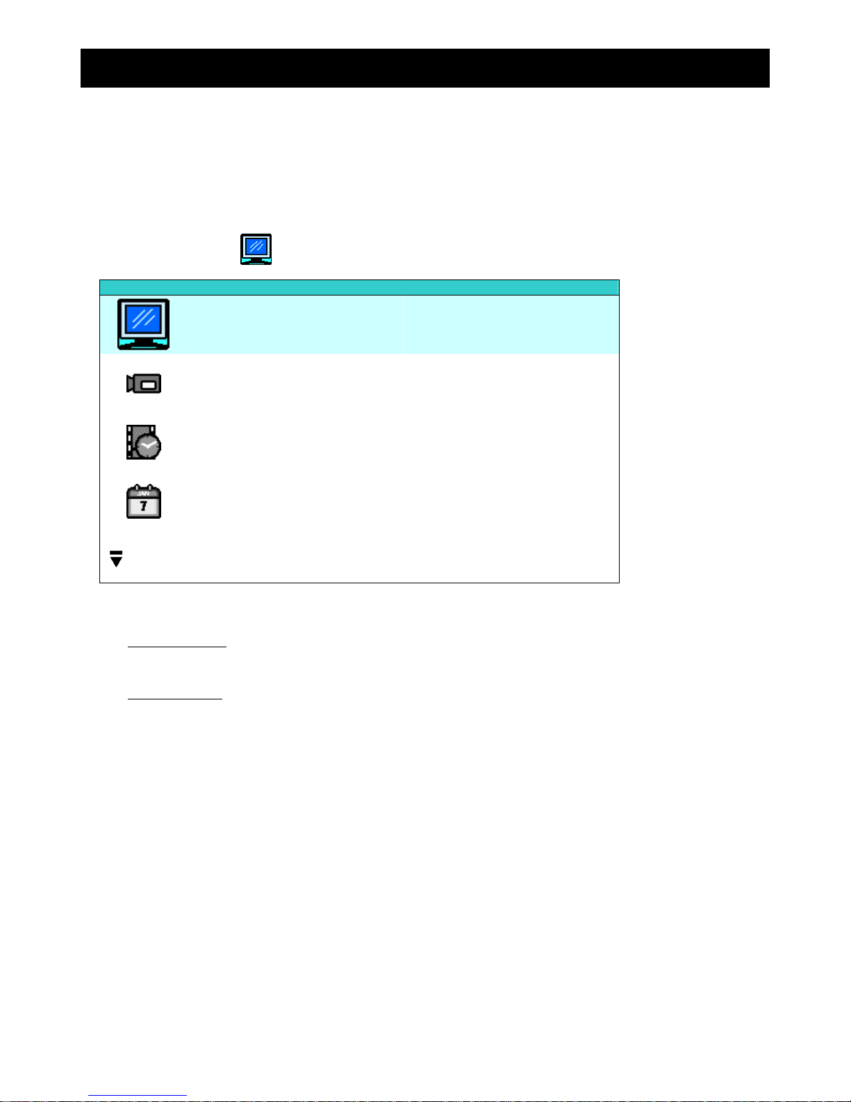
6. QUICK START MENU
Press “MENU” button and enter the password to go to the quick-start menu list. The default admin password is
0000. Users can change the password later. Please refer to “7.2 System Info” at page 34.
6.1 Status
In this menu list, you can check and change some display settings.
Move the cursor to “ ” (STATUS) icon and you will see the following screen:
QUICK START
CHANNEL TITLE ON
EVENT STATUS ON
IMAGE SIZE CIF
QUALITY BEST
IMAGE PER SECOND 120
RECORD TIMER OFF
DETECTION TIMER OFF
DATE 2007 / OCT / 11 09 : 00 : 00
FORMAT Y / M / D
DAYLIGHT SAVING OFF
ADVANCE uv SELECT s BACK t NEXT ENTER
The submenu items are described below:
1) CHANNEL TITLE
Select to display the channel title or not (ON / OFF).
2) EVENT STATUS
Select to display the symbols of the event or not (ON / OFF).
 Loading...