

CPC MultiFlex RTU Installation And Operation Manual
026-1706 Rev 1 10-29-02
MultiFlex RTU Rooftop
Controller Installation and
Operation Manual


1640 Airport Road, Suite 104
Kennesaw, GA 31044
Phone: (770) 425-2724
Fax: (770) 425-9319
ALL RIGHTS RESERVED.
The information contained in this manual has been carefully checked and is believed to be accurate. However, Computer Process Controls, Inc. assumes no responsibility for any inaccuracies that may be contained herein. In no event will
Computer Process Controls, Inc. be liable for any direct, indirect, special, incidental, or consequential damages resulting
from any defect or omission in this manual, even if advised of the possibility of such damages. In the interest of continued
product development, Computer Process Controls, Inc. reserves the right to make improvements to this manual, and the
products described herein, at any time without notice or obligation.
READ ALL INSTRUCTIONS CAREFULLY
If the equipment is not used in the manner specified by the manufacturer, the protection provided
by the equipment may be impaired.
SAVE THIS INSTRUCTION MANUAL
This instruction manual contains important operating instructions for the MultiFlex RTU rooftop
control board.


Table of Contents
1 OVERVIEW OF THE MULTIFLEX RTU ................................................................................................................ 1
1.1. D
IFFERENCES BETWEEN THE MULTIFLEX RTU AND ARTC ....................................................................................... 1
1.2. T
HE RTU’S I/O POINTS................................................................................................................................................ 1
1.3. I
NDEPENDENT SYSTEM CONTROL ................................................................................................................................ 1
2 MOUNTING AND POWERING ................................................................................................................................. 2
2.1. S
NAP-TRACK INSTALLATION........................................................................................................................................ 2
2.2. T
HE PLUG-IN OUTPUT BOARD ..................................................................................................................................... 3
2.3. P
OWERING THE MULTIFLEX RTU BOARD ................................................................................................................... 3
2.3.1. Choosing Transformer Sizes ................................................................................................................................. 4
2.3.2. MultiFlex RTU Power Wiring............................................................................................................................... 4
2.3.2.1. New-Style MultiFlex RTU Boards (with Isolated Power Supply) ..................................................................................... 4
2.3.2.2. Old-Style MultiFlex RTU Boards No Isolated Power Supply) .......................................................................................... 5
2.3.3. Wire Types and Maximum Distances.................................................................................................................... 6
2.4. T
HE MULTIFLEX RTU BATTERY AND BATTERY ENABLE JUMPER ............................................................................. 7
3 THE I/O NETWORK .................................................................................................................................................... 8
3.1. W
IRING TYPES.............................................................................................................................................................. 8
3.1.1. Daisy Chains ......................................................................................................................................................... 8
3.1.2. Network ID Numbers ............................................................................................................................................ 8
3.1.2.1. Numbering the MultiFlex RTU .......................................................................................................................................... 9
3.1.3. Setting the Baud Rate............................................................................................................................................ 9
3.1.4. Setting the Terminating Resistance Jumpers ........................................................................................................ 9
4 RTU INPUT AND OUTPUT SETUP......................................................................................................................... 10
4.1. T
HE INPUTS................................................................................................................................................................. 10
4.1.1. MultiFlex RTU Fixed Input Locations................................................................................................................ 10
4.1.2. Auxiliary Input Types.......................................................................................................................................... 10
4.1.3. Wiring Sensors to the MultiFlex RTU................................................................................................................. 11
4.1.3.1. Wiring ............................................................................................................................................................................... 11
4.1.3.2. Sensor Wiring Types ........................................................................................................................................................ 11
4.1.3.3. Input Type Dip Switches .................................................................................................................................................. 12
4.1.4. Input Connection When Replacing ARTC with RTU .......................................................................................... 12
4.1.5. On-Board Power Connection.............................................................................................................................. 12
4.1.5.1. Current Ratings for On-Board Power Sources ................................................................................................................. 13
4.1.5.2. Powering Sensors Requiring 24VAC Off the Power Transformer................................................................................... 13
4.2. THE OUTPUTS ............................................................................................................................................................. 13
4.2.1. MultiFlex RTU Fixed Outputs............................................................................................................................. 13
4.2.2. MultiFlex RTU Auxiliary Output Types .............................................................................................................. 14
4.2.3. Wiring Outputs to Points..................................................................................................................................... 14
4.2.4. Output Fail-Safe Dip Switches............................................................................................................................ 15
4.2.5. Relay Output Ratings and Fuse Protection......................................................................................................... 15
4.3. A
NALOG OUTPUTS...................................................................................................................................................... 16
4.3.1. Wiring the RTU Analog Output Points ............................................................................................................... 16
5 BOARD STATUS LEDS ............................................................................................................................................. 17
5.1. S
TATUS LED .............................................................................................................................................................. 17
5.2. T
X AND RX LEDS ...................................................................................................................................................... 17
5.3. T
HE CODE A LED ...................................................................................................................................................... 17
Table of Contents MultiFlex RTU Operator’s Guide • v

5.4. THE CODE B LED ...................................................................................................................................................... 18
5.5. R
ELAY OUTPUT LEDS ................................................................................................................................................ 18
6 SOFTWARE OVERVIEW ......................................................................................................................................... 19
6.1. I
NTRODUCTION TO ZONE CONTROL............................................................................................................................ 19
6.2. T
EMPERATURE CONTROL ........................................................................................................................................... 19
6.2.1. Set Points............................................................................................................................................................. 19
6.2.1.1. Set Point Dead Bands ....................................................................................................................................................... 19
6.2.1.2. Stage ON and OFF Delays................................................................................................................................................ 19
6.2.1.3. Summer/Winter and Occupied/Unoccupied Set Points .................................................................................................... 19
6.3. FAN CONTROL ............................................................................................................................................................ 20
6.4. D
EHUMIDIFICATION AND HUMIDIFICATION CONTROL ............................................................................................... 20
6.4.1. Dehumidification Control ................................................................................................................................... 20
6.4.2. Humidification Control ....................................................................................................................................... 20
6.5. E
CONOMIZATION......................................................................................................................................................... 20
6.5.1. Analog Economizers............................................................................................................................................ 21
6.6. C
URTAILMENT ............................................................................................................................................................ 21
6.7. R
EVERSING VALVE CONTROL .................................................................................................................................... 21
6.8. S
TAND-ALONE OPERATION ........................................................................................................................................ 21
6.9. S
ENSOR FAILURES ...................................................................................................................................................... 22
7 THE MULTIFLEX RTU HAND-HELD INTERFACE........................................................................................... 23
7.1. RTU H
7.2. RTU M
7.3. S
7.4. C
AND-HELD TERMINAL STATUS SCREENS........................................................................................................ 23
AIN MENU....................................................................................................................................................... 24
TATUS MENU ............................................................................................................................................................ 24
ONTROL MENU ......................................................................................................................................................... 25
vi • MultiFlex RTU Operator’s Guide 026-1706 Rev 1 10-29-02
1 Overview of the Multi-
Flex RTU
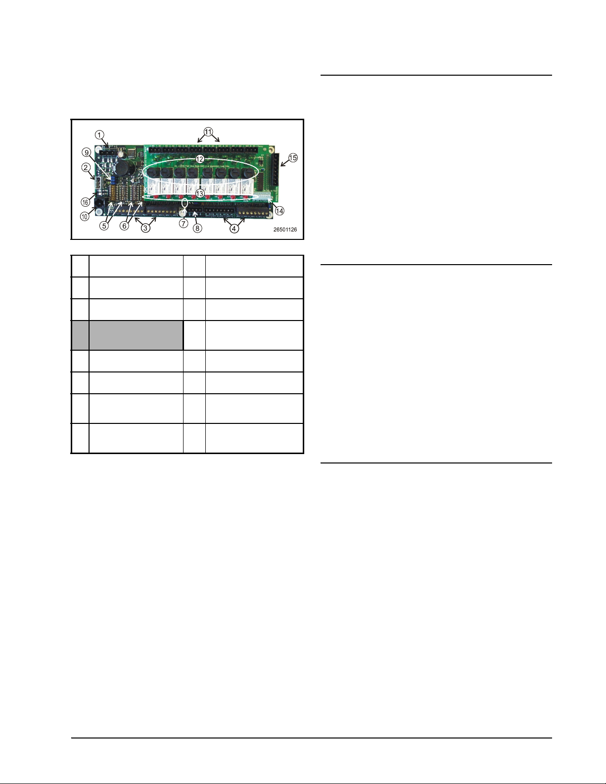
LEGEND
1 INPUT POWER
(24VAC)
2 RS485 I/O NETWORK 10 HAND-HELD TERMI-
3 RTU INPUTS 1-8 11 RELAY OUTPUT CON-
4 RTU INPUTS 9-16 (NOT
ACTIVE FOR RTU)
5NETWORK ID DIP
SWITCHES (S3, S4)
6 INPUT TYPE DIP
SWITCHES (S1, S2)
7 BOARD STATUS LEDs
(Code A, Code B, General
Status)
8 DC POWER OUTPUTS
(3 at +5VDC, 1 at
+12VDC)
Table 1-1 - MultiFlex RTU
9 RS485 I/O TERMINA-
TION JUMPERS
NAL JACK
NECTORS
12 RELAY OUTPUT FUSES
(2A rated, 250V slowblow)
13 RELAY STATUS LEDs
14 OUTPUT FAIL-SAFE
SWITCHES
15 ANALOG OUTPUTS (#1
and #2 active for RTU, #3
and #4 inactive)
16 NETWORK STATUS
LEDs
1.1. Differences Between the MultiFlex RTU and ARTC
The MultiFlex RTU is a hardware replacement for CPC’s ARTC rooftop unit control
boards, which are now discontinued. The RTU
firmware is in every way identical to the ARTC,
and is compatible with both Einstein BX and the
REFLECS BCU controllers. The only difference
between the RTU and ARTC is the RTU uses
the MultiFlex hardware platform, which is
smaller and more robust.
1.2. The RTU’s I/O Points
The compact size of the RTU allows technicians to easily field-mount the RTU in a rooftop
unit or enclosure close to it, allowing for easy
local connection of sensors and transducers. The
board has eight analog inputs, pre-configured for
quick connection to space temperature sensors,
supply and return air temperature sensors, and
fan and compressor proofs. Its eight relay outputs, rated 2.0 amps max, are used for activating
and deactivating fans, heat and cool stages,
economizers, and other systems or devices.
The MultiFlex Rooftop Unit Board (RTU)
(P/N 810-3062) is a “smart” combination input/
1.3. Independent System
Control
output board designed to control package rooftop HVAC units. The MultiFlex RTU is capable
of controlling heat and cool stages, fans, humidification and dehumidification devices, economizers using on-board I/O and control
algorithms, as well as monitor and interact with
other building control systems and peripherals
(such as smoke alarms and CO2 sensors).
The RTU can control a rooftop unit independently without the need of a central controller
(such as CPC’s Einstein BX Refrigeration Controller). However, the RTU is designed to interface with an Einstein BX or BCU to allow it to
work with other RTUs together to control large
zones. Networking RTU to a central controller
also allows you to view status on Einstein &
UltraSite32 status screens, report alarms, and
control dehumidification.
The RTU’s configuration can be programmed either with a CPC Hand-Held Terminal (HHT) or through the Einstein front panel.
Differences Between the MultiFlex RTU and ARTC Overview of the MultiFlex RTU • 1
2 Mounting and Power-
ing
The MultiFlex boards are usually mounted
by the refrigeration equipment manufacturer.
Therefore, the installer need only make the necessary connections between the boards and the
site controller(s).
In some instances, an installer may be
required to mount an I/O board. There are no
restrictions on the location of these boards; however, for ease of network configuration, it is recommended that the boards be located adjacent to
the Einstein. I/O boards may be mounted without an enclosure, but they should be mounted in
a location that is not easily accessible to avoid
tampering or damage.
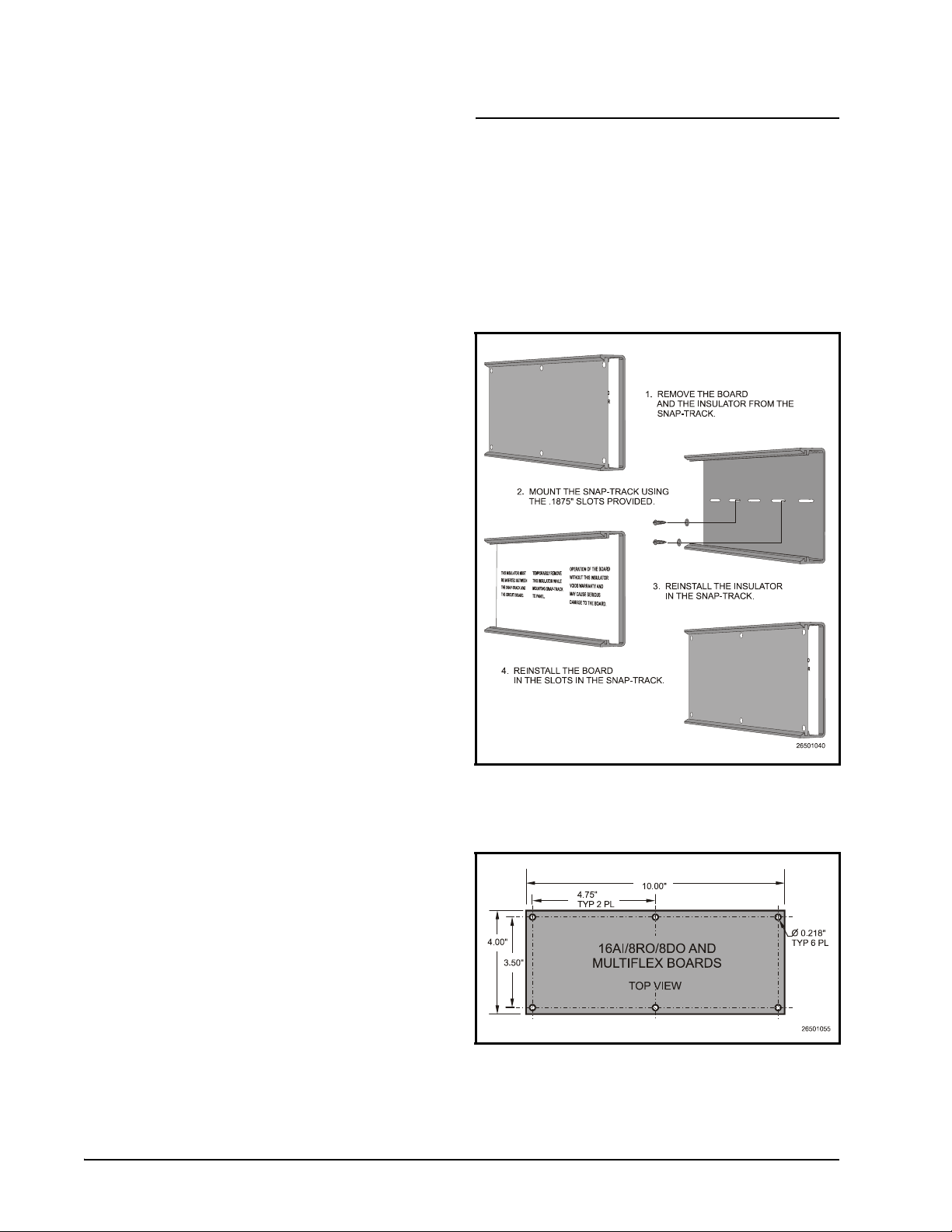
2.1. Snap-Track Installation
MultiFlex boards not supplied in a custom
panel or other enclosure are supplied with a
snap-track for easy installation. The insulation
sheet and I/O board must be removed from the
track before the track is mounted. The snap-track
is mounted using the 0.1875” mounting slots.
Figure 2-1 shows this installation procedure.
Figure 2-1 - MultiFlex Snap-Track Mounting
Figure 2-2 provides mounting dimensions
for the MultiFlex board.
Figure 2-2 - MultiFlex Board Dimensions
2 • MultiFlex RTU Operator’s Guide 026-1706 Rev 1 10-29-02
2.2. The Plug-In Output Board
The additional board makes the MultiFlex
RTU boards considerably taller than the MultiFlex 16 and other CPC I/O boards. If you will be
mounting these boards in an enclosure, the board
will need at least 2.5" of clearance between the
base board and the panel door.
2.3. Powering the MultiFlex
RTU Board
All models of MultiFlex require a 24VAC
Class 2 input power source. The MultiFlex RTU
requires the power source to be non-center-
tapped.
CPC supplies a wide variety of 24VAC
transformers with varying sizes and either with
or without center taps. Table 2-1 shows the
transformer sizes and whether they are centertapped or non-center-tapped.
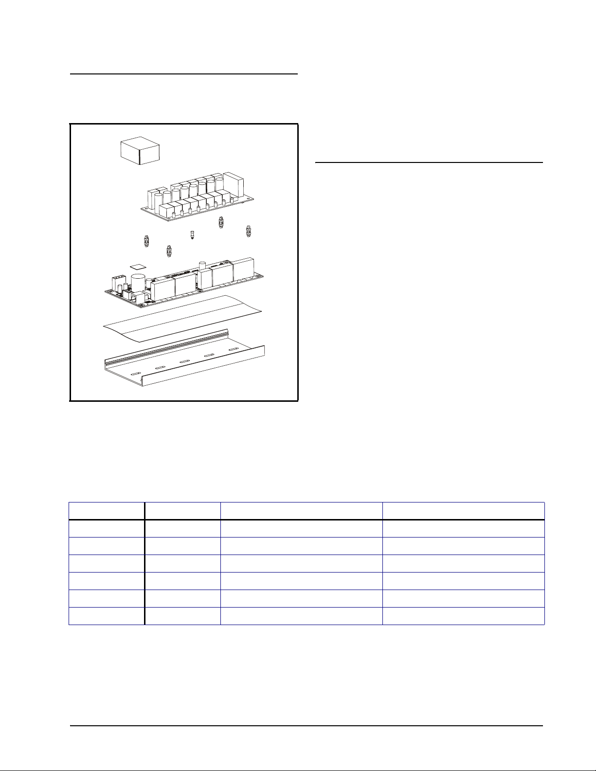
Figure 2-3 - Exploded View — MultiFlex RTU
The MultiFlex RTU has an output sub-board
that plugs to the top of the base board. Typically,
these boards are shipped with the output board
pre-installed on the board using stand-offs, so no
additional hardware setup should be necessary.
Xformer P/N VA Rating Primary Voltage Center Tap?
640-0041 50 VA 110 VAC No
640-0042 50 VA 220 VAC No
640-0056 56 VA Multi-tap (120/208/240 VAC) Yes
640-0050 75 VA 110 VAC No
640-0045 75 VA 220 VAC No
640-0080 80 VA Multi-tap (120/208/240 VAC) Yes
Table 2-1 - Transformers Compatible with MultiFlex
The Plug-In Output Board Mounting and Powering • 3
2.3.1. Choosing Transformer Sizes
In most site installations, a single trans-
former will power multiple devices. Choose a
transformer with a VA rating large enough to
power all devices that will be attached to it.
Table 2-2 gives the VA ratings of the MultiFlex
RTU in conjunction with other MultiFlex
boards. Refer to your site controller’s manual for
VA ratings of the other I/O boards that may be
powered by one of these transformers.
Unit VA VAC Center
tapped?
MultiFlex 16 624Yes
MultiFlex 88,
88AO, 168,
and 168AO
MultiFlex RTU 15 24 NO
Table 2-2 - Device Power Requirements
15 24 NO
2.3.2. MultiFlex RTU Power Wiring
The MultiFlex RTU boards do not use a cen-
ter tap. Instead, the 0V terminal on the board
should be connected to a separate Earth ground.
Important! The rules that must be fol-
lowed when connecting a MultiFlex RTU
board to a transformer are different depending on whether you have a "new style" MultiFlex board with an isolated power supply (all
MultiFlex boards shipped after November 1,
2002) or an "old style" MultiFlex board (all
MultiFlex boards shipped before November
1, 2002).
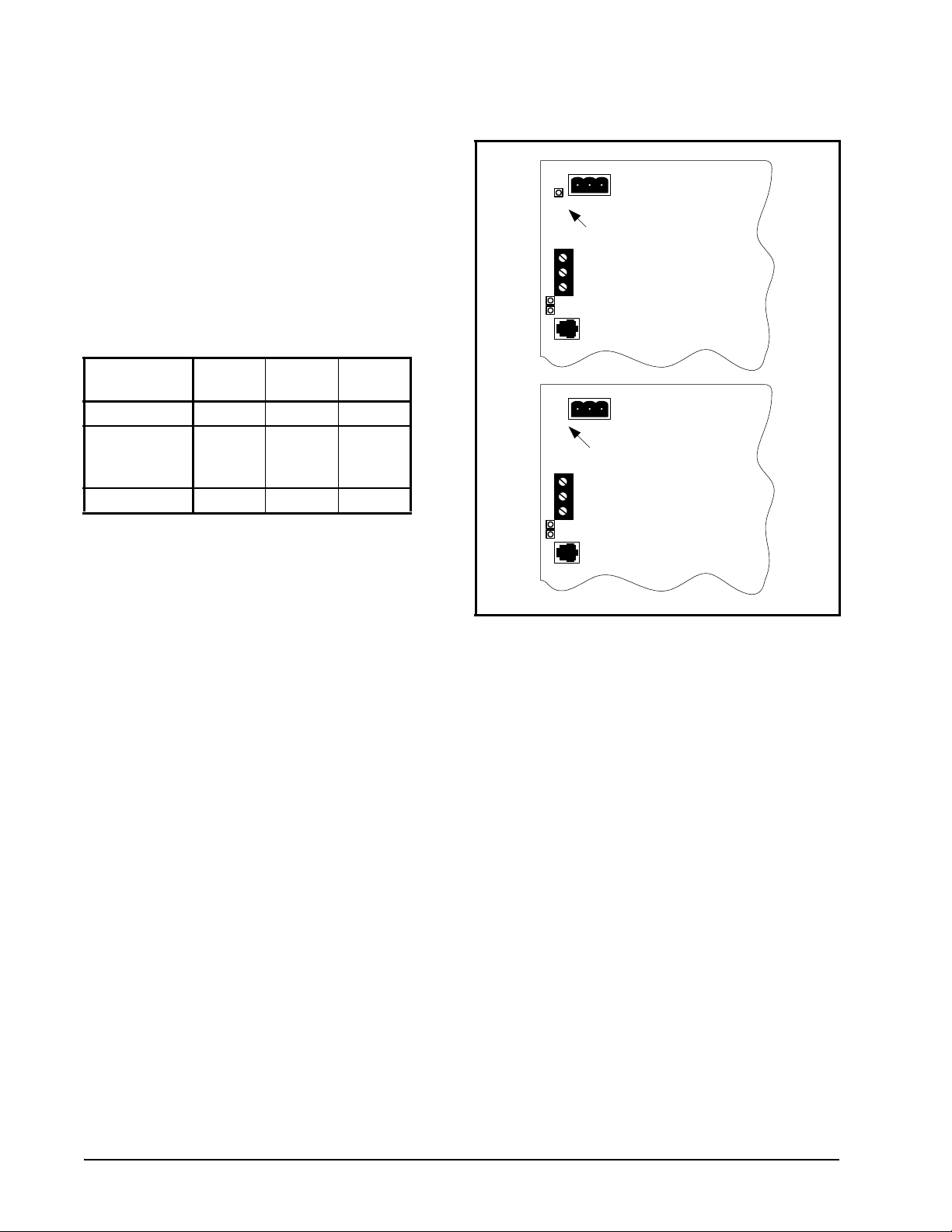
A new-style MultiFlex board has a green
power LED located next to the 24VAC connection terminal in the upper right corner of the circuit board (see Figure 2-4 for reference).
24 VAC
POWER LED
New Style
MultiFlex Board
(Top Left Corner)
24 VAC
NO POWER LED
Old Style
MultiFlex Board
(Top Left Corner)
Figure 2-4 - New-Style vs. Old-Style MultiFlex Board
If there is a green power LED next to the
connector, your MultiFlex is a new-style Multi-
Flex -- refer to Section 2.3.2.1., New-Style MultiFlex RTU Boards (with Isolated Power Supply)
for power wiring instructions.
If there is no green power LED next to the
connector, your MultiFlex is an old-style Multi-
Flex -- refer to Section 2.3.2.2., Old-Style MultiFlex RTU Boards No Isolated Power Supply) for
power wiring instructions.
2.3.2.1. New-Style MultiFlex RTU Boards (with Isolated Power Supply)
The new-style MultiFlex board can be connected to any of the center-tapped transformers
mentioned in Table 2-2, provided the 0V terminal of the board is connected to an Earth ground.
4 • MultiFlex RTU Operator’s Guide 026-1706 Rev 1 10-29-02

A center-tapped transformer may power
both center-tapped and non-center-tapped
devices at the same time, as long as none of the
non-center-tapped MultiFlex boards are oldstyle MultiFlex boards. If an old-style Multi-
Flex shares the same center-tapped transformer
as a device that uses the center tap, the old-style
MultiFlex will be damaged. Figure 2-5 shows
how to wire a non-center tapped device to a center-tapped transformer.
You may also tie one side of the secondary
(but not BOTH sides) to an earth ground, provided none of the boards powered by the same
transformer are old-style MultiFlex boards (see
Section 2.3.2.2.).
Figure 2-6 - Non-Center-Tapped Transformer Wiring
2.3.2.2. Old-Style MultiFlex RTU
Boards No Isolated Power Supply)
Figure 2-5 - Wiring Non-Center Tapped MultiFlex Boards to
Transformers With a Center Tap
In addition, the MultiFlex RTU boards can
be powered by one of the 50VA or 75VA noncenter-tapped transformers listed in Table 2-1 on
page 3. Figure 2-6 shows how to wire the transformers to the MultiFlex boards.
Like the new-style MultiFlex board, the oldstyle MultiFlex board can be connected to any of
the center-tapped transformers mentioned in
Table 2-2, provided you follow the following
three rules:
Rule 1: Ground the 0V terminal on the oldstyle MultiFlex board to an Earth ground.
Do not connect the center tap of the transformer to the 0V terminal.
Rule 2: Do not power an old-style MultiFlex
non-center-tapped board with a transformer
that is also powering a center-tapped device.
This means you cannot connect an old-style
MultiFlex non-center tapped board to a transformer that is powering a MultiFlex 16, 16AI,
8RO, 4AO, 8DO, or any previous generation
CPC board that uses center-tapped power. Doing
so will destroy the MultiFlex board.
Rule 3: The secondary of the center-tapped
transformer must not be grounded on any
side.
Powering the MultiFlex RTU Board Mounting and Powering • 5
 Loading...