

CPC MultiFlex PAK User Manual
026-1712 Rev 3 03-JAN-2008
MultiFlex PAK Compressor/
Condenser Control Board
User’s Guide


1640 Airport Road, Suite 104
Kennesaw, GA 31044
Phone: (770) 425-2724
Fax: (770) 425-9319
ALL RIGHTS RESERVED.
The information contained in this manual has been carefully checked and is believed to be accurate. However, Computer Process Controls, Inc. assumes no responsibility for any inaccuracies that may be contained herein. In no event will
Computer Process Controls, Inc. be liable for any direct, indirect, special, incidental, or consequential damages resulting
from any defect or omission in this manual, even if advised of the possibility of such damages. In the interest of continued
product development, Computer Process Controls, Inc. reserves the right to make improvements to this manual, and the
products described herein, at any time without notice or obligation.
This product is covered under one or more of the following Computer Process Controls U.S. patents: 6360553,
6449968, 6378315, 6502409, 6578374, and Alsenz U.S. patents 4612776, 4628700, and 4535602.
READ ALL INSTRUCTIONS CAREFULLY
If the equipment is not used in the manner specified by the manufacturer, the protection provided
by the equipment may be impaired.
SAVE THIS INSTRUCTION MANUAL
This instruction manual contains important operating instructions for the MultiFlex PAK boards.


Table of Contents
1 OVERVIEW OF THE MULTIFLEX PRODUCT LINE .......................................................................................... 1
1.1. M
ULTIFLEX PAK ......................................................................................................................................................... 1
1.1.1. Hardware .............................................................................................................................................................. 1
2 MOUNTING AND POWERING ................................................................................................................................. 2
2.1. S
NAP-TRACK INSTALLATION........................................................................................................................................ 2
2.2. T
HE PLUG-IN OUTPUT BOARD ..................................................................................................................................... 3
2.3. P
OWERING THE MULTIFLEX ......................................................................................................................................... 3
2.3.1. Choosing Transformer Sizes ................................................................................................................................. 4
2.3.2. MultiFlex Combination Input/Output Board Power Wiring................................................................................. 4
2.3.2.1. New-Style MultiFlex Combination I/O Boards (with Isolated Power Supply).................................................................. 4
2.3.2.2. Old-Style MultiFlex Combination I/O Boards (No Isolated Power Supply)...................................................................... 5
2.3.3. Wire Types and Maximum Distances.................................................................................................................... 6
3 THE I/O NETWORK .................................................................................................................................................... 7
3.1. W
3.2. D
IRING TYPES.............................................................................................................................................................. 7
AISY CHAINS ............................................................................................................................................................. 7
3.2.1. Network ID Numbers ............................................................................................................................................ 7
3.2.1.1. Numbering the MultiFlex PAK .......................................................................................................................................... 7
3.2.2. Setting the Baud Rate............................................................................................................................................ 8
3.2.3. Setting the Terminating Resistance Jumpers ........................................................................................................ 8
4 I/O BOARD INPUT AND OUTPUT SETUP.............................................................................................................. 9
4.1. T
HE INPUTS................................................................................................................................................................... 9
4.1.1. Input Types Supported by the MultiFlex PAK ...................................................................................................... 9
4.1.2. The PAK Default Input Assignments................................................................................................................... 10
4.1.3. Connecting Sensors to Input Boards................................................................................................................... 10
4.1.3.1. Wiring ............................................................................................................................................................................... 10
4.1.3.2. Sensor Wiring Types ........................................................................................................................................................ 10
4.1.3.3. Input Type Dip Switches .................................................................................................................................................. 10
4.1.4. Power Connection............................................................................................................................................... 11
4.1.4.1. Current Ratings for On-Board Power Sources ................................................................................................................. 11
4.1.4.2. Powering Sensors Requiring 24VAC Off the Power Transformer................................................................................... 11
4.1.5. Sensor Types for MultiFlex Input Points ............................................................................................................ 11
4.2. T
HE RELAY OUTPUTS................................................................................................................................................. 12
4.2.1. Output Types Supported by the MultiFlex PAK.................................................................................................. 12
4.2.2. The PAK Default Output Assignments................................................................................................................ 12
4.2.3. Wiring.................................................................................................................................................................. 12
4.2.4. Output Fail-Safe Dip Switches............................................................................................................................ 12
4.2.5. Relay Output Ratings and Fuse Protection......................................................................................................... 13
4.3. T
HE ANALOG AND DIGITAL OUTPUTS ....................................................................................................................... 14
4.3.1. Digital/Analog Output Types Supported by the MultiFlex PAK......................................................................... 14
4.3.2. The PAK Default Analog/Digital Output Assignments ....................................................................................... 14
5 BOARD STATUS LEDS ............................................................................................................................................. 15
5.1. S
TATUS LED .............................................................................................................................................................. 15
5.2. T
X AND RX LEDS ...................................................................................................................................................... 15
5.3. C
ODE A AND CODE B LEDS ...................................................................................................................................... 15
5.4. R
ELAY OUTPUT LEDS................................................................................................................................................ 16
Table of Contents • v

6 PAK SOFTWARE OVERVIEW................................................................................................................................ 17
6.1. C
OMPRESSOR GROUPS ................................................................................................................................................ 17
6.1.1. Maximum # of Groups......................................................................................................................................... 17
6.1.2. Required Setpoints............................................................................................................................................... 17
6.1.3. Compressor Group Stage Activation and Deactivation...................................................................................... 17
6.1.4. Compressor Control Strategies........................................................................................................................... 18
6.1.4.1. Cyclic ................................................................................................................................................................................ 18
6.1.4.2. Fixed Steps........................................................................................................................................................................ 18
6.1.5. Suction Float ....................................................................................................................................................... 19
6.1.5.1. Suction Float Input Sources.............................................................................................................................................. 20
6.1.5.2. Defrost Inhibit................................................................................................................................................................... 20
6.1.5.3. Bad Case Temp Inhibit ..................................................................................................................................................... 20
6.1.5.4. Suction Float During Loss of Communication ................................................................................................................. 21
6.2. CONDENSER CONTROL................................................................................................................................................ 21
6.2.1. Condenser Control Strategies ............................................................................................................................. 21
6.2.1.1. Staged Fans ....................................................................................................................................................................... 21
6.2.1.2. VSD Fan ........................................................................................................................................................................... 21
6.2.1.3. Fan Sequencer................................................................................................................................................................... 21
6.2.2. Minimum Pressure Set Point............................................................................................................................... 22
6.2.3. Discharge Pressure Max..................................................................................................................................... 22
6.2.4. Condenser Spray ................................................................................................................................................. 22
6.2.5. Interlock .............................................................................................................................................................. 22
6.2.6. Quiet Mode.......................................................................................................................................................... 23
6.2.6.1. Exiting or Cancelling Quiet Mode .................................................................................................................................... 23
6.2.7. Safety Features.................................................................................................................................................... 23
6.2.7.1. Discharge Trip .................................................................................................................................................................. 23
6.2.8. Alarms ................................................................................................................................................................. 23
7 MULTIFLEX PAK E2 INTERFACE........................................................................................................................ 24
7.1. A
DDING/DELETING A PAK ......................................................................................................................................... 24
7.1.1. Adding a PAK...................................................................................................................................................... 24
7.1.2. Deleting a PAK.................................................................................................................................................... 25
7.2. S
ETTING THE "CONNECTED" AND "READ SETPOINTS" ATTRIBUTES.......................................................................... 25
7.2.1. Verifying Online Status ....................................................................................................................................... 25
7.3. V
IEWING THE PAK STATUS SCREEN.......................................................................................................................... 26
7.3.1. Inputs and Set Points........................................................................................................................................... 26
7.3.2. Compressor Groups ............................................................................................................................................ 27
7.3.3. Compressor Status............................................................................................................................................... 27
7.3.4. Condenser Fans................................................................................................................................................... 27
7.3.5. Connected and PAK State ................................................................................................................................... 28
7.4. P
ROGRAMMING THE PAK USING E2........................................................................................................................... 28
7.4.1. Screen 1: General................................................................................................................................................ 28
7.4.2. Screen 2: Comp Setpts......................................................................................................................................... 28
7.4.3. Screen 3: Cond Setpts ......................................................................................................................................... 29
7.4.4. Screen 4: Float Setup .......................................................................................................................................... 29
7.4.5. Screen 5: PAK Inputs .......................................................................................................................................... 29
7.4.6. Screen 6: Outputs................................................................................................................................................ 30
7.4.7. Screen 7: PAK Outputs ....................................................................................................................................... 30
7.4.8. Screen 8: Fixed Steps .......................................................................................................................................... 30
7.4.9. Screen 9: Safety................................................................................................................................................... 31
7.4.10. Screen B: Alarms............................................................................................................................................... 31
8 MULTIFLEX PAK HAND-HELD TERMINAL INTERFACE ............................................................................. 32
8.1. T
HE HHT INTERFACE ................................................................................................................................................. 32
vi • MultiFlex I/O Board I&O Manual 026-1712 Rev 3 03-JAN-2008

8.1.1. Navigation........................................................................................................................................................... 32
8.2. PAK S
8.3. PAK S
TART SCREENS................................................................................................................................................. 33
TATUS SCREENS............................................................................................................................................... 33
8.3.1. Status Screen 1 .................................................................................................................................................... 33
8.3.2. Status Screen 2 .................................................................................................................................................... 33
8.3.3. Status Screen 3 .................................................................................................................................................... 33
8.3.4. Status Screen 4 .................................................................................................................................................... 34
8.3.5. Status Screen 5 .................................................................................................................................................... 34
8.3.6. Status Screen 6 .................................................................................................................................................... 34
8.3.7. Status Screen 7 .................................................................................................................................................... 35
8.3.8. Status Screen 8 .................................................................................................................................................... 35
8.3.9. Status Screen 9 .................................................................................................................................................... 35
8.3.10. Status Screen 10 ................................................................................................................................................ 35
8.3.11. Status Screen 11 ................................................................................................................................................ 35
8.4. PAK C
ONFIGURATION SCREENS ................................................................................................................................ 36
8.4.1. The PAK Configuration Menu ............................................................................................................................ 37
8.4.1.1. 1 - General ........................................................................................................................................................................ 37
8.4.1.2. 2 - Comp SP...................................................................................................................................................................... 38
8.4.1.3. 3 - Outs.............................................................................................................................................................................. 40
8.4.1.4. 4 - CondSP........................................................................................................................................................................ 41
8.4.1.5. 5 - Input............................................................................................................................................................................. 43
8.4.1.6. 6 - Safety ........................................................................................................................................................................... 44
Table of Contents • vii


1 Overview of the Multi-
Flex Product Line
The MultiFlex line of control system boards
provides a wide variety of input, output, and
smart control solutions, all of which are based on
a single universal hardware platform. The board
design uses flash-uploadable firmware and plugin expansion boards to configure the base platform board and apply it for use as an input
board, relay output board, analog output board,
or a combination I/O board.
1.1. MultiFlex PAK
The PAK is a distributed pack controller that
controls compressors and condenser fans. The
PAK can control up to 16 compressors, controlled in up to 8 compressor groups.
The PAK can control up to 4 condenser fan
groups containing up to 8 total condenser fans.
The PAK condenser control strategy is sequential TD control with setpoint/deadband using ON
and OFF delays. The PAK supports use of both
single-speed fan stages and VS fans.
1.1.1. Hardware
The MultiFlex PAK boards consist of two
circuit boards: a bottom layer with 16 combination digital/analog inputs, and a plug-in top layer
which contains a combination of 8 relay outputs
and 4 analog DC voltage outputs, which can be
used as digital or analog outputs.
The communication interface is RS485 I/O
using the Standard Extended Address Form for
CPC Distributed Controllers. Currently, the PAK
is designed to interface with the CPC E2 RX
controller, and the previous generation refrigeration controller, the Einstein RX.
MultiFlex PAK Overview of the MultiFlex Product Line • 1
2 Mounting and Power-
ing
The MultiFlex boards are usually installed
by the refrigeration or building equipment manufacturer. Therefore, the installer need only
make the necessary connections between the
boards and the site controller(s).
In some instances, an installer may be
required to mount an I/O board. There are no
restrictions on the location of these boards; however, for ease of network configuration, it is recommended that the boards be located adjacent to
the E2. I/O boards may be mounted without an
enclosure, but they should be mounted in a location that is not easily accessible to avoid tampering or damage.
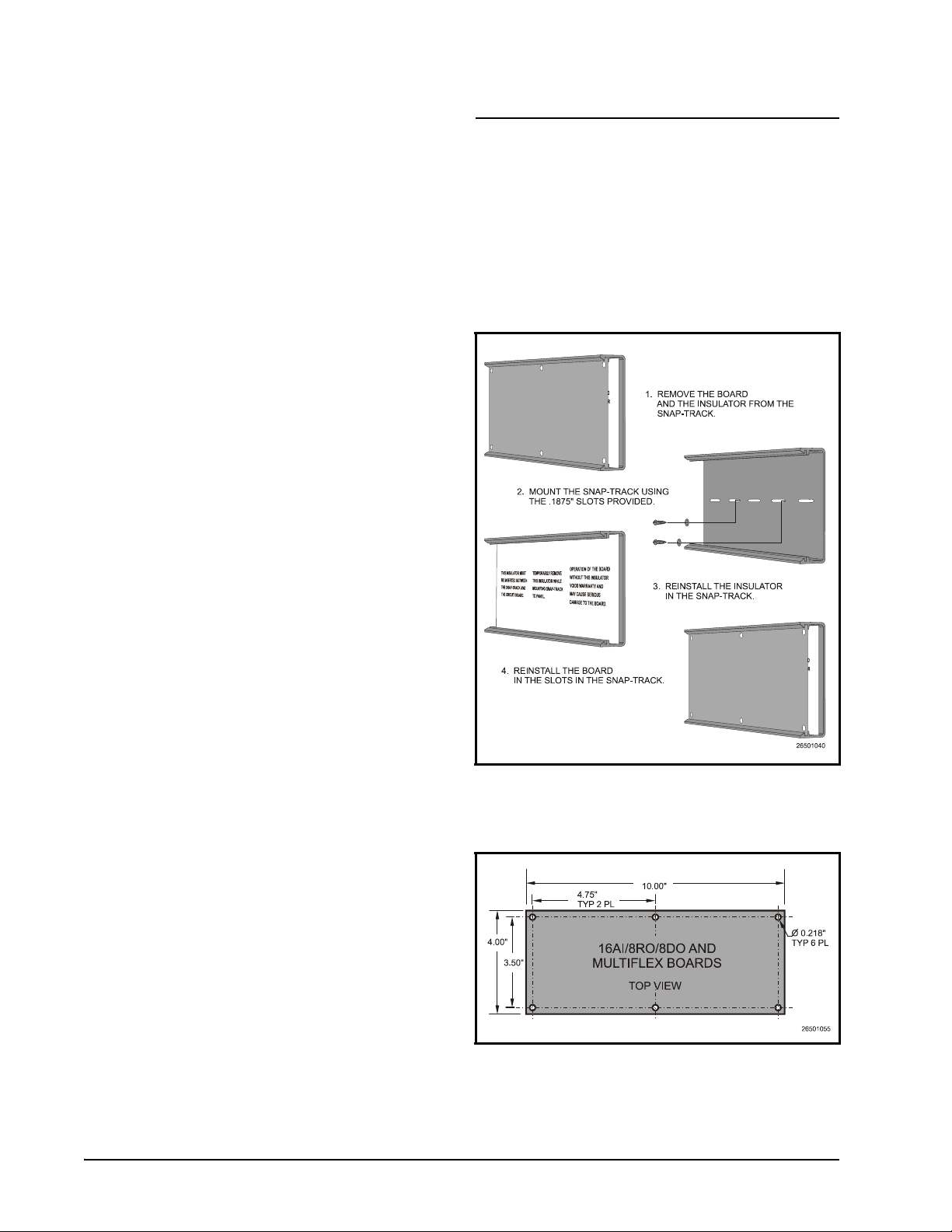
2.1. Snap-Track Installation
MultiFlex boards not supplied in a custom
panel or other enclosure are supplied with a
snap-track for easy installation. The insulation
sheet and I/O board must be removed from the
track before the track is mounted. The snap-track
is mounted using the 0.1875” mounting slots.
Figure 2-1 shows this installation procedure.
Figure 2-1 - MultiFlex Snap-Track Mounting
Figure 2-2 provides mounting dimensions
for the MultiFlex board.
Figure 2-2 - MultiFlex Board Dimensions
2 • MultiFlex I/O Board Operator’s Guide 026-1712 Rev 3 03-JAN-2008
2.2. The Plug-In Output Board
The additional board makes the MultiFlex
combination boards considerably taller than the
MultiFlex 16 and all previous-generation CPC I/
O boards. If you will be mounting these boards
in an enclosure, the board will need at least 2.5"
of clearance between the base board and the
panel door.
2.3. Powering the MultiFlex
All models of MultiFlex require a 24VAC
Class 2 input power source. The MultiFlex PAK
requires the power source to be center-tapped.
CPC supplies a wide variety of 24VAC transformers with varying sizes and either with or
without center taps. Table 2-1 shows the trans-
former sizes and whether they are center-tapped
or non-center-tapped.
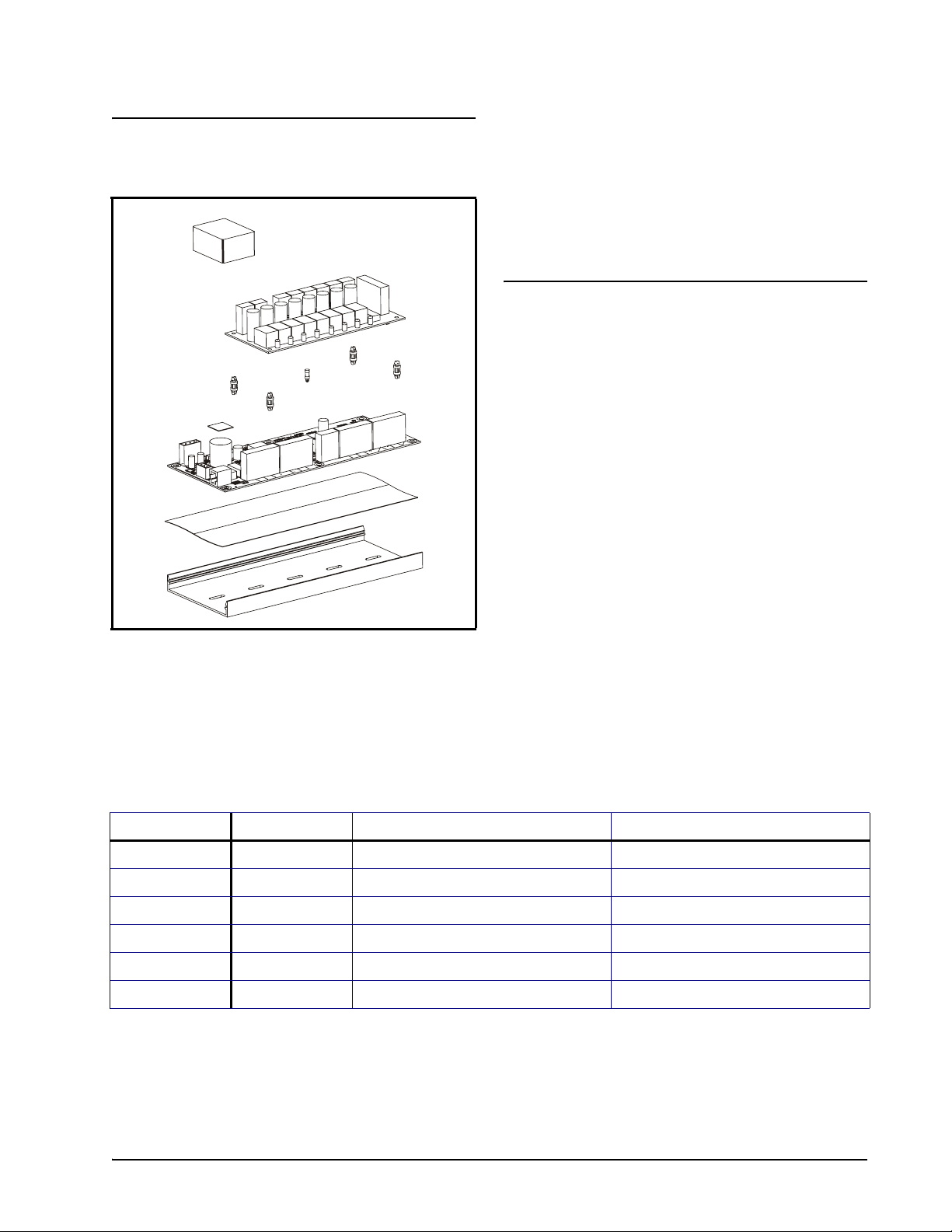
Figure 2-3 - Exploded View -- MultiFlex Combination I/O Board
All MultiFlex boards except the MultiFlex
16 have output sub-boards that plug in to the top
of the base board. These boards are shipped with
the output board pre-installed on the board using
stand-offs, so no additional hardware setup
should be necessary.
Xformer P/N VA Rating Primary Voltage Center Tap?
640-0041 50 VA 110 VAC No
640-0042 50 VA 220 VAC No
640-0056 56 VA Multi-tap (120/208/240 VAC) Yes
640-0050 75 VA 110 VAC No
640-0045 75 VA 220 VAC No
640-0080 80 VA Multi-tap (120/208/240 VAC) Yes
Table 2-1 - Transformers Compatible with MultiFlex Board
The Plug-In Output Board Mounting and Powering • 3
2.3.1. Choosing Transformer Sizes
In most site installations, a single trans-
former will power multiple devices. Choose a
transformer with a VA rating large enough to
power all devices that will be attached to it.
Table 2-2 gives the VA ratings of the MultiFlex
board products. Refer to your site controller’s
manual for VA ratings of the other I/O boards
that may be powered by one of these transformers.
Unit VA VAC Center
tapped?
MultiFlex PAK,
CUB, RTU,
and RCB
MultiFlex 16 624Yes
MultiFlex 88,
88AO, 168,
168AO and
168DO
Table 2-2 - Device Power Requirements
15 24 NO
15 24 NO
2.3.2. MultiFlex Combination Input/ Output Board Power Wiring
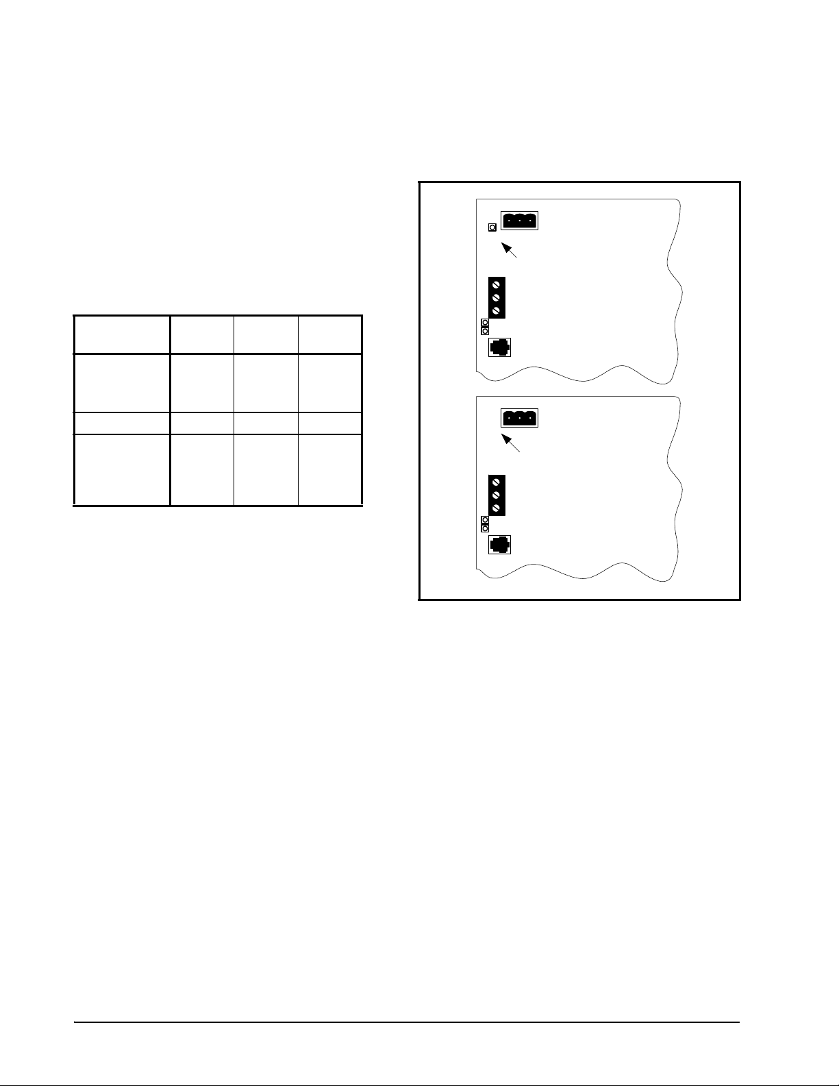
A new-style MultiFlex PAK board has a
green power LED located next to the 24VAC
connection terminal in the upper right corner of
the circuit board (see Figure 2-4 for reference).
24 VAC
POWER LED
New Style
MultiFlex Board
(Top Left Corner)
24 VAC
NO POWER LED
Old Style
MultiFlex Board
(Top Left Corner)
The MultiFlex PAK boards do not use a center tap. Instead, the 0V terminal on the board
should be connected to a separate Earth ground.
Important! The rules that must be followed when connecting a MultiFlex PAK
board to a transformer are different depending on whether you have a "new style" MultiFlex board with an isolated power supply (all
MultiFlex boards shipped after November 1,
2002) or an "old style" MultiFlex board (all
MultiFlex boards shipped before November
1, 2002).
Figure 2-4 - New-Style vs. Old-Style MultiFlex Board
If there is a power LED next to the connector, your MultiFlex is a new-style MultiFlex --
refer to Section 2.3.2.1., New-Style MultiFlex
Combination I/O Boards (with Isolated Power
Supply) for power wiring instructions.
If there is no power LED next to the connector, your MultiFlex is an old-style MultiFlex -refer to Section 2.3.2.2., Old-Style MultiFlex
Combination I/O Boards (No Isolated Power
Supply) for power wiring instructions.
2.3.2.1. New-Style MultiFlex Combina-
tion I/O Boards (with Isolated
Power Supply)
The new-style MultiFlex board can be connected to any of the center-tapped transformers
mentioned in Table 2-2, provided the 0V termi-
nal of the board is connected to an Earth ground.
4 • MultiFlex I/O Board Operator’s Guide 026-1712 Rev 3 03-JAN-2008

A center-tapped transformer may power
both center-tapped and non-center-tapped boards
at the same time, as long as none of the non-
center-tapped MultiFlex boards are old-style
MultiFlex boards. If an old-style MultiFlex
shares the same center-tapped transformer as a
device that uses the center tap, boards on the network will be damaged. Figure 2-5 shows how to
wire a non-center tapped device to a centertapped transformer.
You may also tie one side of the secondary
(but not BOTH sides) or the center tap to an
earth ground, provided none of the boards powered by the same transformer are old-style MultiFlex boards (see Section 2.3.2.2.).
Figure 2-6 - Non-Center-Tapped Transformer Wiring
Figure 2-5 - Wiring Non-Center Tapped MultiFlex Boards to
Transformers With a Center Tap
In addition, the MultiFlex combination
boards can be powered by one of the 50VA or
75VA non-center-tapped transformers listed in
Table 2-1 on page 3. Figure 2-6 shows how to
wire the transformers to the MultiFlex boards.
All wire connections to earth ground should
be less than six (6) inches long and use a wire
gauge of at least 14AWG.
2.3.2.2. Old-Style MultiFlex Combination I/O Boards (No Isolated
Power Supply)
Like the new-style MultiFlex board, the oldstyle MultiFlex board can be connected to any of
the center-tapped transformers mentioned in
Table 2-2, provided you follow the following
three rules:
Rule 1: Ground the 0V terminal on the oldstyle MultiFlex board to an Earth ground.
Do not connect the center tap of the transformer to the 0V terminal.
Rule 2: Do not power an old-style MultiFlex
non-center-tapped board with a transformer
that is also powering a center-tapped device.
Powering the MultiFlex Mounting and Powering • 5

This means you cannot connect an old-style
MultiFlex non-center tapped board to a transformer that is powering a MultiFlex 16, 16AI,
8RO, 4AO, 8DO, a Gateway board, or any previous generation CPC board that uses centertapped power. Doing so will destroy the MultiFlex board.
the transformer that supplies power to them is
not enough to be concerned with. But it is very
important not exceed this maximum wire length
or the boards will malfunction.
Use these formulas to determine if the wire
gauge you are using fits within specification:
Rule 3: The secondary of the transformer
must not be grounded on any side.
Verify that neither side of the transformer
secondary is connected to earth ground before
powering the old-style MultiFlex board. A
grounded secondary will damage the MultiFlex
board.
In addition, the old-style MultiFlex combination boards can be powered by one of the 50VA
or 75VA non-center-tapped transformers listed
in Table 2-1 on page 3. Figure 2-6 shows how to
wire the transformers to the MultiFlex boards.
2.3.3. Wire Types and Maximum
Distances
For powering I/O boards, use only the listed
wire types from Table 2-3. Three-conductor non-
shielded cables are the recommended wire for
connecting between the center tapped transformer and the I/O boards. Shielded cable should
not be used for power wiring. The center tap
should be wired with the third conductor to earth
ground at the transformer.
14 AWG:
Feet = 0.40/(VA/24) x 0.005
18 AWG:
Feet = 0.40/(VA/24) x 0.013
(VA is the total VA rating of the I/O boards)
For example, if you had an 80 VA load:
14 AWG: 24 ft. (rounded down)
18 AWG: 9 ft.
Figure 2-7 - Power Wire Lengths
Each MultiFlex board should have its 0V terminal taken to a short, solid earth ground.
Power Wiring Types
14 AWG Belden 9495 or equivalent
18 AWG Belden 9493 or equivalent
Table 2-3 - Power Wiring Types
The wire length from the transformer and the
number of boards connected to the same wire
determines the type wire gauge used. In most
cases, the distance between the I/O boards and
6 • MultiFlex I/O Board Operator’s Guide 026-1712 Rev 3 03-JAN-2008
3 The I/O Network
All MultiFlex PAK boards and controllers
use an RS485 network connection to communicate with E2 site controllers. Technicians who
are familiar with CPC’s previous generation
16AI, 8IO, and ARTC boards will find the network setup procedure for the MultiFlex boards
to be very much the same.
3.1. Wiring Types
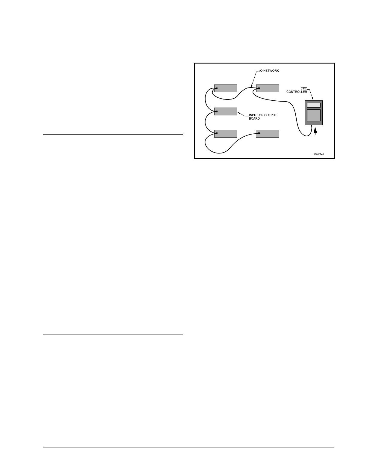
A diagram of this network arrangement is
shown in Figure 3-1.
TERMINATION
TERMINATION
CPC specifies all RS485 I/O and MODBUS
wiring used by the E2 must be Belden 8641
(24AWG, 300V, CPC P/N 135-8641); Belden
8761 (22 AWG, 300V not stocked by CPC); or a
600V-shielded 22AWG equivalent stocked by
CPC (P/N 135-0600). These are two-connector
shielded twisted pair cable that support a maximum daisy chain cable distance of 4000 feet
(1219 m) between the E2 and the end device on
the network.
Provided the cable can be routed away from
noise generators and avoid running in parallel
with high-voltage wire, any of the three specified cables will provide adequate shielding from
external noise. For more instructions on best
practices for minimizing noise, refer to publication 026-1903, E2 Controller Wiring Practices,
available in the Product Manuals section of the
Emerson Retail Solutions website (http://
www.emersonretailsolutions.com/library).
Figure 3-1 - I/O Network Configurations
3.2.1. Network ID Numbers
Each device on an RS485 segment has a network dip switch that must be used to assign the
board a unique network ID number.
The network ID number makes a board
unique from other boards on the network of the
same type. This allows the site controller to find
it and communicate with it.
Boards of the same type should be numbered
in sequence, starting with one and continuing
with two, three, etc.
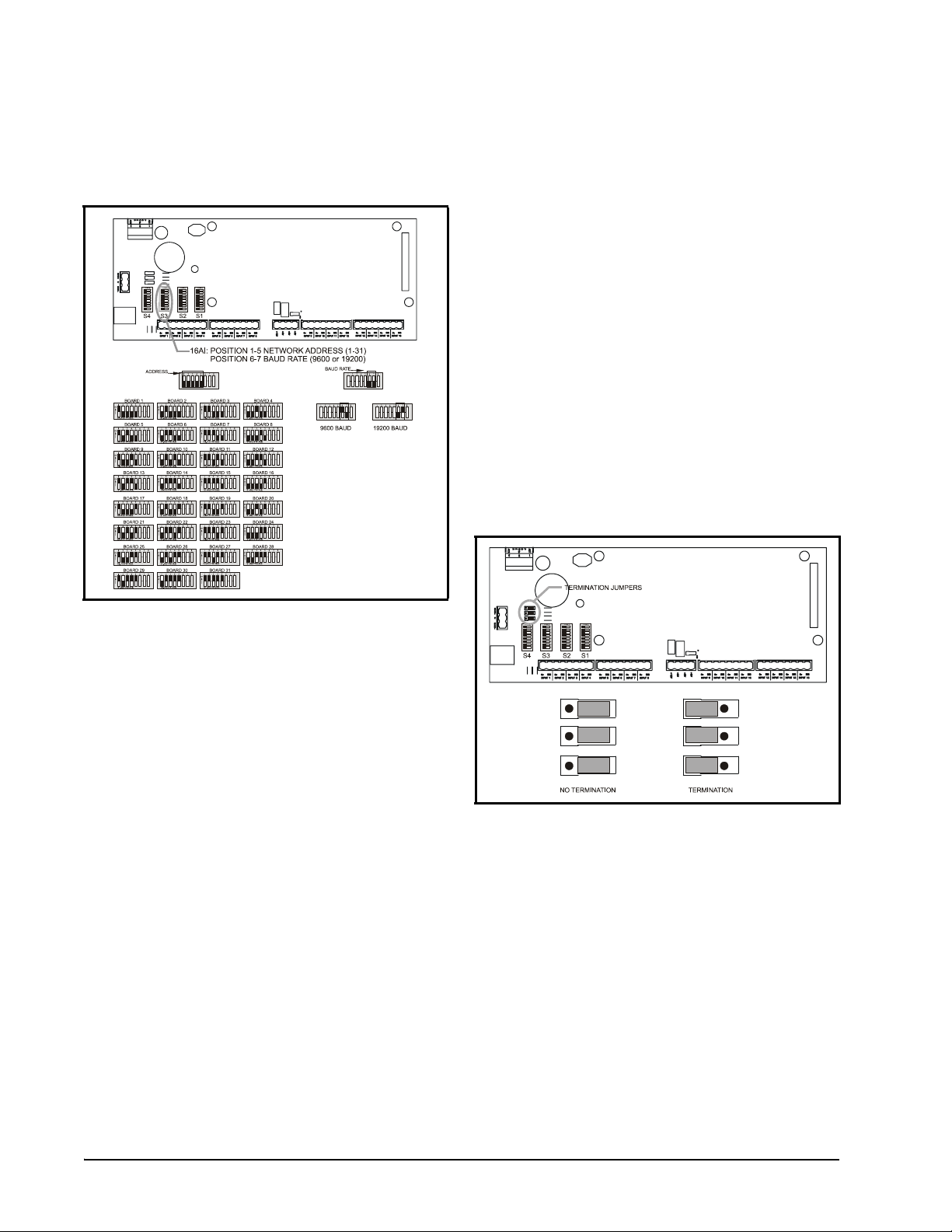
3.2.1.1. Numbering the MultiFlex PAK
The network ID on the MultiFlex PAK is set
using the first five dip switches on dip switch
bank S3. Refer to Figure 3-2 for dip switch setting instructions.
3.2. Daisy Chains
The RS485 Input/Output (I/O) network is
wired in a daisy-chain configuration. In a daisy
chain, boards are wired together in series with no
branches or "star configurations," and the network is terminated at either end of the daisy
chain.
Wiring Types The I/O Network • 7
NOTE: The MultiFlex PAK may only be
numbered up to 16, since E2 will only speak to
a maximum of 16 PAK boards. A PAK numbered above 16 will be ignored.
3.2.3. Setting the Terminating Resistance Jumpers
All MultiFlex boards and other RS485
devices have a set of terminating resistance
jumpers (one jumper for each wire lead). These
jumpers are labeled JP2, JP3, and JP4 on the
MultiFlex board.
The purpose of the jumpers is to indicate the
two ends, or termination points, of the segment.
On a daisy chain, one device at the beginning
and one device on the end must be terminated.
On the MultiFlex, this is done by placing all
three termination jumpers in the OUT (toward
the left edge of the board) position. To unterminate a MultiFlex, these jumpers must be set to
the IN (toward the center of the board) position.
Figure 3-3 shows the termination jumper settings for all MultiFlex boards.
Figure 3-2 - 16 Network ID and Baud Rate Switches
3.2.2. Setting the Baud Rate
All I/O boards have dip switches that determine the baud rate at which they communicate.
Currently, the baud rate dip switch in network
components may be set at either 9600 or 19200
baud. Either may be used -- refer to your site
controller’s user manual for the baud rate recommendation (currently 9600 baud for both
REFLECS and E2 controllers).
On all MultiFlex boards, switches 6 and 7 on
S3 are used to set the baud rate. To communicate
at 9600 baud, set switch #6 UP and #7 DOWN.
For 19200 baud, set switch #6 DOWN and #7
UP. Refer to Figure 3-2 for a visual look at how
the switches must be set.
Figure 3-3 - I/O Network Termination Jumper Settings
8 • MultiFlex I/O Board Operator’s Guide 026-1712 Rev 3 03-JAN-2008
 Loading...