

CPC 537-3094 Technical Bulletin
TECHNICAL BULLETIN
Part #: 026-4212 Revision 0 Date: 10/17/2006
Ethernet Gateway Board Installation Instructions
Overview
The Ethernet Gateway Board (CPC P/N 537-3094) provides a hardware platform that can be used
to communicate with RS485 or RS232 devices through an Ethernet connection. The Ethernet
Gateway Board can be used in various applications, such as providing a web or HHT-accessible
interface to CPC I/O Network devices (such as the MultiFlex).
Mounting
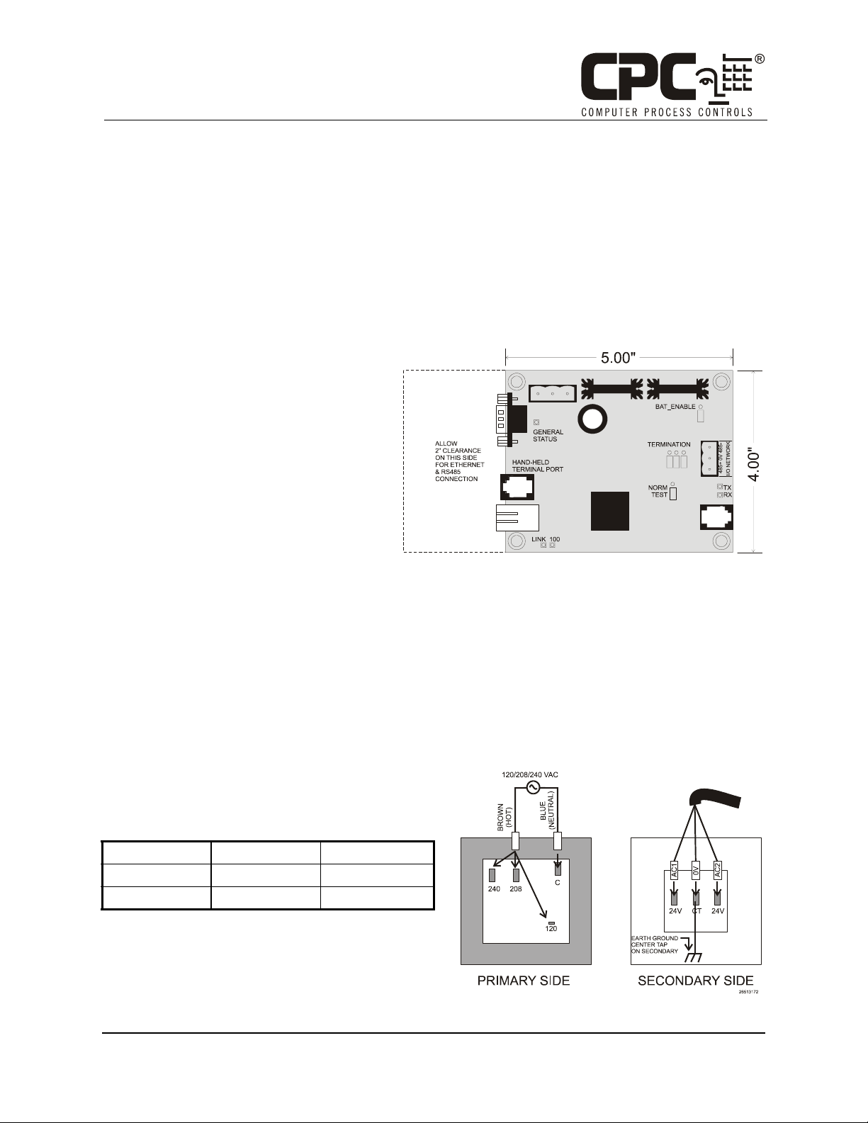
The Ethernet Gateway Board is typically
installed near the devices it will be communicating with. The board is designed to fit
in a standard 4” snap-track or it may be
mounted in a panel or against a wall using
stand-offs. Follow the dimensions in Fig-
ure 1 for panel mounting. Leave at least 2
inches of clearance on the left side of the
board to allow room for the Ethernet and
RS232 connections.
Figure 1 - Ethernet Gateway Board Diagram
The Ethernet Gateway Board must be
mounted in an environment with ambient temperature between -40°F and 150°F with a non-condensing humidity between 5% and 95%.
Powering
The Ethernet Gateway Board requires 24VAC power from a Class 2 center-tapped transformer.
CPC supplies several sizes of center-tapped transformers for powering multiple 16AIs, 8ROs, and
other RS485 peripheral boards of the E2, Einstein, and REFLECS systems.
Figure 2 shows how to connect the 56VA and
80VA transformers to the Ethernet Gateway Board
power connector.
Three-Board Six-Board
P/N
Power Rating
Table 1-US and Canada Power Ratings for
640-0056 640-0080
5 6 VA 8 0 VA
CPC Transformers
Figure 2 - Power Transformer Wiring
COMPUTER PROCESS CONTROLS - http://www.cpcus.com/ Page 1
Technical Bulletin - Ethernet Gateway Board Installation Instructions
Part #: 026-4212 Revision 0 Date: 10/17/2006
Networking
RS485 Networking
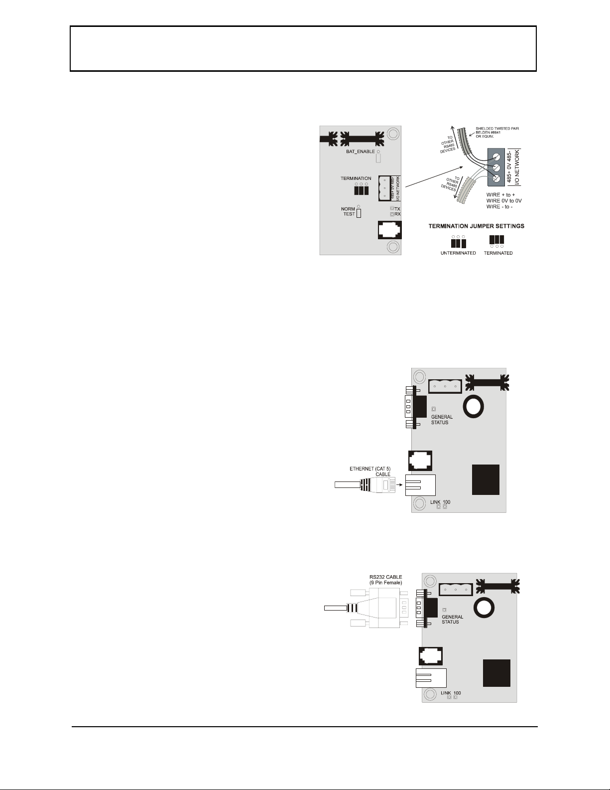
The RS485 network port is located on the right
side of the Ethernet Gateway board. This port is
where you must connect your RS485 devices.
Using shielded three-conductor network cable
(Belden #8641 or equivalent), connect the
RS485 I/O Network wire to the three-terminal
connector on the Ethernet Gateway Board as
shown in Figure 3. For further information
about how RS485 networks are configured,
refer to your site controller’s user manual.
The RS485 network termination jumpers are
located next to the RS485 network port. If the Ethernet Network Gateway board is at either end of
the RS485 daisy-chain, set the termination jumpers to the UP (terminated) position. Otherwise, if
the board is not at the end of the network daisy-chain, set the termination jumpers to the DOWN
(unterminated) position.
Figure 3 - RS485 to Gateway Networking
Ethernet Networking
The Ethernet port is located on the lower left
side of the Ethernet Gateway Board (see Figure
4). The port accepts a standard CAT5 cable with
RJ45 connector. Insert the RJ45 connector tabside down into the port until it clicks. Connect
the other end of the cable to the network hub or
switch.
Like all TCP/IP devices, the Ethernet Gateway
Board requires an IP address, Gateway IP
address, and other network information. These
values are configured through the Hand-Held
Terminal (HHT) interface.
RS232 Networking
The RS232 port is located on the upper left side
of the Ethernet Gateway Board (see Figure 5).
Use any standard serial cable with a 9-pin
female connector. Plug the connector into the
RS232 port and secure the connection using the
screws on the cable connector.
Figure 4 - Ethernet Connection
RS232 baud rate settings are configured
through the Hand-Held Terminal (HHT) interface.
COMPUTER PROCESS CONTROLS - http://www.cpcus.com/ Page 2
Figure 5 - Ethernet Connection
 Loading...