

CPC 210-2006 Installation Instructions Manual
COMPU
TER PROCESS CONTROL
S
®
(
)
technical bulletin
Installation Instructions: Wall-Mount
Dewpoint Probe (210-2006)
The Wall-Mount Dewpoint Probe (P/N 210-2006) measures dewpoint for indoor applications such as
anti-sweat heater control and HVAC dehumidification. The sensor’s linear 0-5VDC output makes the
sensor compatible with the E2 site controller and all legacy CPC site control products that use MultiFlex
and 16AI input boards.
Specifications
Property Description/Value Property Description/Value
Operating Temperature -5°C — 55°C (-23°F — 131°F) Relative Humidity Range 0-95% RH
Storage Temperature -40°C — 80°C (-40°F — 176°F) Accuracy +/- 1.2°C (+/- 3.6°F)
Supply Voltage 12-35VDC or 24VAC Output Voltage 0-5VDC
Current consumption 12mA, maximum External Load R
min. 10kΩ
L
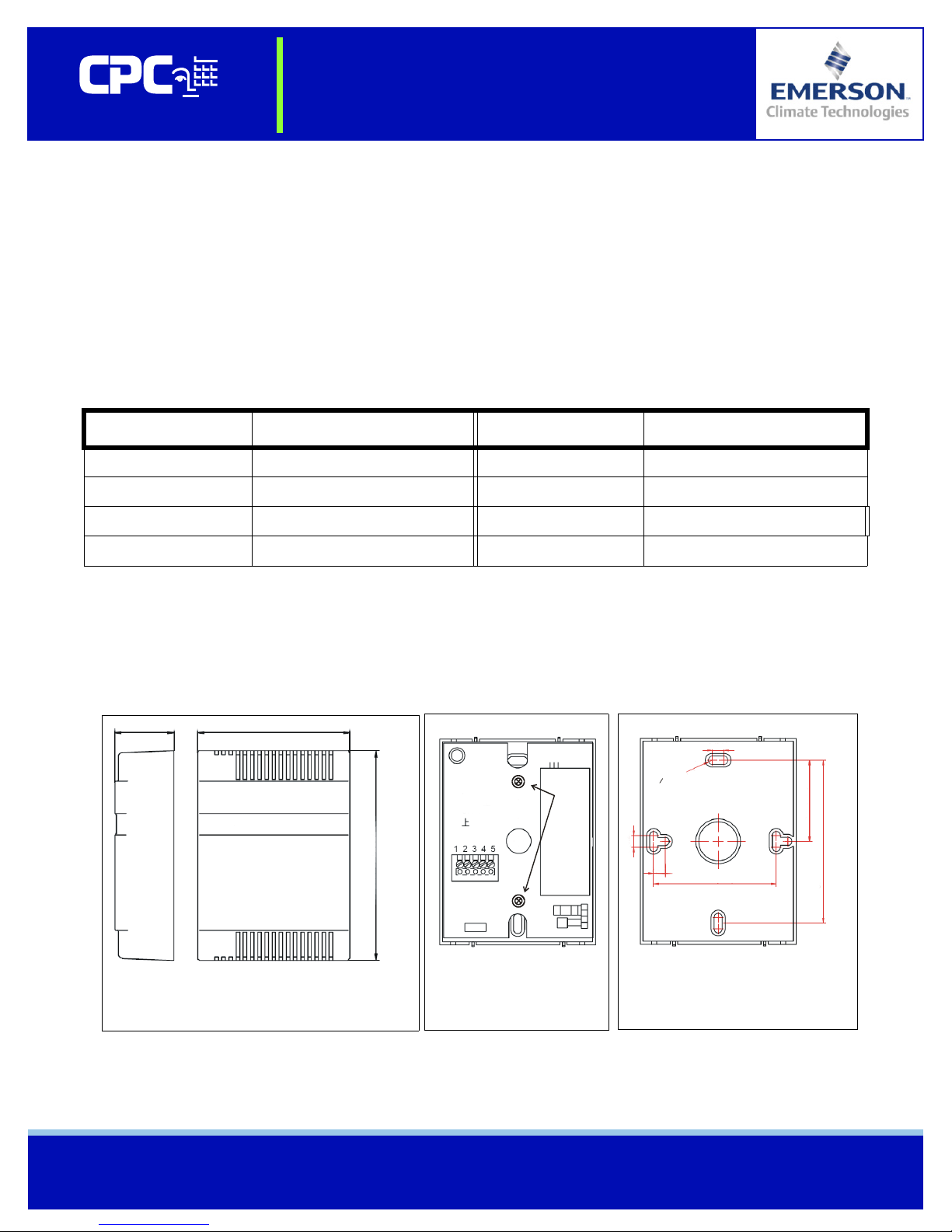
Mounting
Mount the dewpoint probe enclosure against a flat surface (such as a wall or riser) or junction box.
Remove the front cover, and remove the two screws that attach the sensor’s circuit board to the rear
mounting plate (Figure 2). Attach the mounting plate to the mounting surface (Figure 3), then reattach
the circuit board and snap the cover back in place.
1.3"
(33 mm)
DEWPOINT ENCLOSURE DIMENSIONS
WITH COVER ATTACHED
Figure 1 - Enclosure Dimensions
3.35"
(85 mm)
4.33"
(110 mm)
REMOVE
SCREWS
Figure 2 - Circuit Board
0.23" (6 mm)
O0.16" (4.2mm)
0.23" (6 mm)
3.29"
0.23" (6 mm)
Figure 3 - Mounting Plate Dimensions
2.49"
(63.3 mm)
(83.5 mm)
Document Part # 026-4824 Rev 0 5/8/2007 Page 1 of 2
©2007 Emerson Climate Technologies Retail Solutions, Inc. This document may be photocopied for personal use.
Visit our website at http://www.emersonretailsolutions.com/ for the latest technical documentation and updates.
technical bulletin
Installation Instructions: Wall-Mount Dewpoint Probe
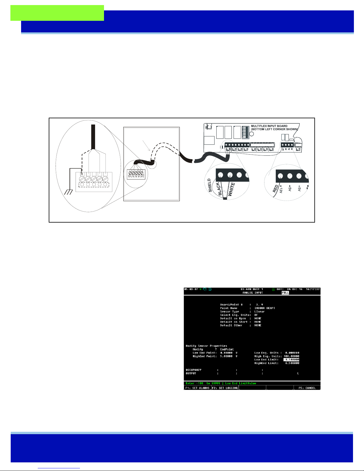
Power and Input Wiring
To wire the Dewpoint Probe to a MultiFlex or 16AI input point, use Belden #8771 three-conductor shielded 22AWG wire (or equivalent). Figure 5 shows the connection point on the Dewpoint
Probe’s circuit board and where to connect the wires to the probe as well as the input point. The
sensor is powered by one of the +12VDC power supply terminals on the MultiFlex or 16AI input
boards.
RUN CABLE
THROUGH
WALL O R
CONDUIT
AND FEED
END THROUGH
HOLE IN
MOUNTING PLATE
1 2 3 4 5
1 2 3 4 5
CIRCUIT BOARD, FRONT VIEW
(COVER REMOVED)
CABLE
(BELDEN #8771)
CONNECT
TERMINAL 1
TO EARTH
GROUND
CABLE
(BELDEN #8771)
SHIELD (GND)
1 2 3 4 5
BLACK (SGND)
WHITE (SIG)
RED (12VDC)
Figure 5 - Dewpoint Probe Wiring
Terminal 1 of the Dewpoint Probe must be connected to a solid earth ground. Also, the input type
dip switch on the MultiFlex or 16AI input board must be set to the DOWN position. Input type
dip switches for points #1 through #8 are located on switch bank S1, while points #9 through #16
are located on switch bank S2.
E2 Input Setup
NOTE: Do NOT set up this probe with a sensor type of
“Dewpoint”; this setting only works for old-style CPC
Dewpoint Probes (P/N 203-1902). This probe must be set
up with a sensor type of “Linear.”
1. Log into the E2 and press
mary).
2. Highlight the input point the Dewpoint Probe is connected to, and press
3. When prompted to select the data type, press
(Analog).
4. In the Analog Input setup screen, enter the following
information in the fields listed below:
• Name: A description of the sensor’s function
and/or location (e.g. INDOOR DEWPT).
• Sensor Type: Linear
• Eng. Unit: DF
• Low Eng Units: 0.0
• High Eng Units: 100
5. Press
J to save changes and exit the Analog Input setup screen.
I (Input Sum-
A (Setup).
Document Part # 026-4824 Rev 0 5/8/2007 Page 2 of 2
©2007 Emerson Climate Technologies Retail Solutions, Inc. This document may be photocopied for personal use.
Visit our website at http://www.emersonretailsolutions.com/ for the latest technical documentation and updates.
 Loading...