

CPC 203-5850 Installation Instructions Manual

TECHNICAL BULLETIN
Part #: 026-4800 Revision 0 Date: 0 9/13/2000
COMPUTER PROCESS CONTROLS - http://www.cpcus.com/ Page 1
New CPC Humidity Sensor Installation Instructions
Overview
CPC is supplying a new relative humidi ty (RH) sensor model (P/N 203-5850) to replace the sensor previously supplied with its REFLECS and Einstein controls system products (P/N 203-5850).
The new model is func tionally identical to the pre vious RH sensor model with the same + 0-5VDC
output signal, but with distinct differences in the way it must be mounted and wired.
Mounting
The dimensions of the sensor are 4½” x 2¾”. To mount the sensor, pull the front cover from the
rear mounting plate of the sensor. Using the two mounting holes on the mounting plate, screw the
plate against a flat surface such as a wall or column. The sensor may also be mounted to a standard electrical wiring box. Make sure the plate is mounted so that the orientation arrow on the left
side of the mounting plate points UP (refer to picture on the reverse side of this page).
When used indoors, mount the sensor in a central location within the zone to be measured, away
from doors, windows, vents, heaters, and outside walls that could affect temperature readings.
The sensor should be at least four feet from the floor, and no higher than necessary to prevent
tampering.
Wiring
Cable Type
The cable type used to connect the humidity sensor with the CPC input board is Belden #8771
(shielded, 3-conductor 22AWG).
Wire Connections
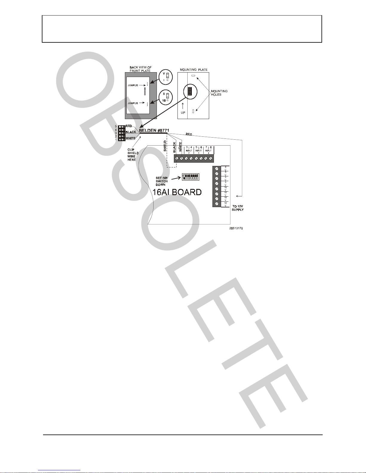
Connect the sensor cable from the five-pin connector on the RH sensor’s mounting plate to a
point on a CPC 16AI input board or equivalent.
1. Connect the RED (power) wire from sensor terminal #5 to one of the +12VDC supply terminals on the
16AI.
2. Connect the BLACK (ground) wire from sensor terminal #3 to the ODD-NUMBERED terminal of the 16AI
point to w h ich you wan t to connect the sensor.
3. Clip the BARE (shie ld) wire at the sensor end of the cable. On the 16AI end of the cable, connect the B ARE
wire to the same ODD-NUMBERED terminal you connec ted the BLACK wire to in step 2.
4. Connect the WHITE (signal) wire from sensor terminal #1 to the EVEN-NUMBERED terminal of the 16AI
point to w h ich you wan t to connect the sensor.
OB
SOL
E
TE
Technical Bulletin - New CPC Humidity Sensor Installation Instructions
Part #: 026-4800 Revision 0 Date: 09/13/2000
COMPUTER PROCESS CONTROLS - http://www.cpcus.com/ Page 2
RH Sens or Jump er Settings
On the back side of the RH sensor’s front cover plate, there are two three-pin jumpers on the circuit board. These jumpers determi ne whether the sensor’s output signal will be voltage or current
(V - I) and 5VDC or 10VDC (5 - 10). Set both jumpers in the UP position (as shown in diagram)
so that the V-I jumper is set to “V” and the 5-10 jumper is set to “5.”
Input Board Dip Switch Settings
On the 16AI board, locate the input type dip switch that corresponds to the point the RH sensor is
connected to, and set this switch to the DOWN position.
Replacing the RH Sensor Front Cover
After wiring and setting the jumpers on the RH sensor, replace the sensor’s front cover, making
sure the five pins on the front cover’s circuit board plug in to the receptacle on the mounting plate.
If installed correctly, the front cover should snap into place.
Figure 1 - RH Sensor Wiring and Installation
OB
SOL
E
TE
 Loading...