

CPC 203-5771 Installation Instructions Manual
TECHNICAL BULLETIN
Part #: 026-4807 Revision 0 Date: 02/26/2003
Duct-Mounted Humidity Sensor (P/N 203-5771)
Installation Instructions
CPC specs a duct-mounted relative humidity (RH) sensor with a 0-5VDC output for use in building control and anti-sweat control applications using CPC input boards.
Specifications
Sensing Element
Accuracy
Stability
Operating
Humidity Range
Temperature
Coefficient
Digitally profiled thin-film capacitive
±2% RH over the range 20%-90% RH
±1%@ 20°C (68°F) annually for 2 years
0-100% RH
±0.03% RH /°C over 0-60°C (32-140°F)
Analog Output
Scaling
Input Power
EMC
Conformance
0-5VDC; 3-wire, observe polarity
0-100% RH
12VDC
EN 50081-1, EN 50082-1, EN 61000-4-4,
EN 61000-4-5, EN 61000-4-3, ENV
50204, EN 61000-4-6
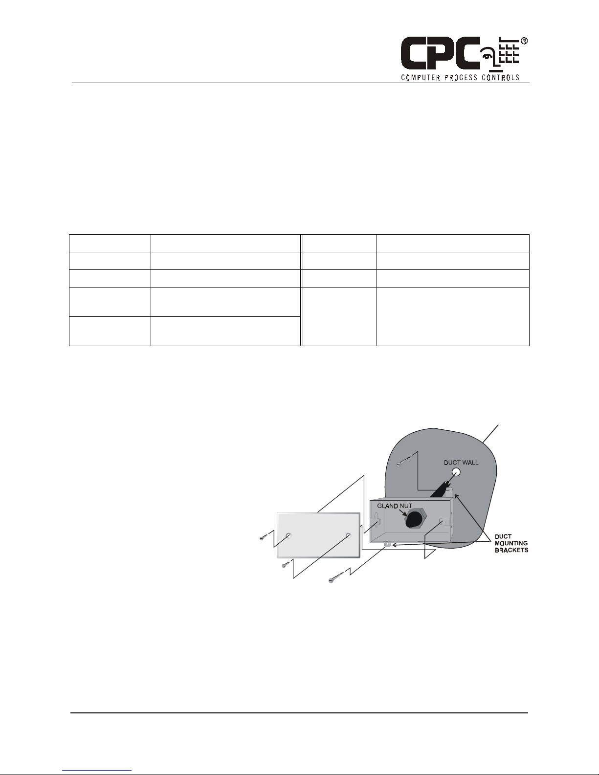
Choosing a Mounting Location
Select a supply air duct that draws air from the area in which you wish to measure relative humidity. You may mount the sensor in any orientation provided the sensor element is in the air stream.
Mounting
1. Cut a small circular hole in the duct large
enough for the sensor tube to fit through.
2. Bolt the sensor enclosure against the outside of
the duct wall so that the sensor element fits
through the hole and into the duct. The enclosure may be mounted horizontally (as shown in
Figure 1) or vertically. The screws should be
tight enough for the foam gasket around the
bottom of the sensor to form an airtight seal
between the hole in the duct wall and the outside air.
COMPUTER PROCESS CONTROLS - http://www.cpcus.com/ Page 1
Figure 1 - Humidity Sensor - Exploded View
Technical Bulletin - Duct-Mounted Humidity Sensor (P/N 203-5771) Installation Instructions
Part #: 026-4807 Revision 0 Date: 02/26/2003
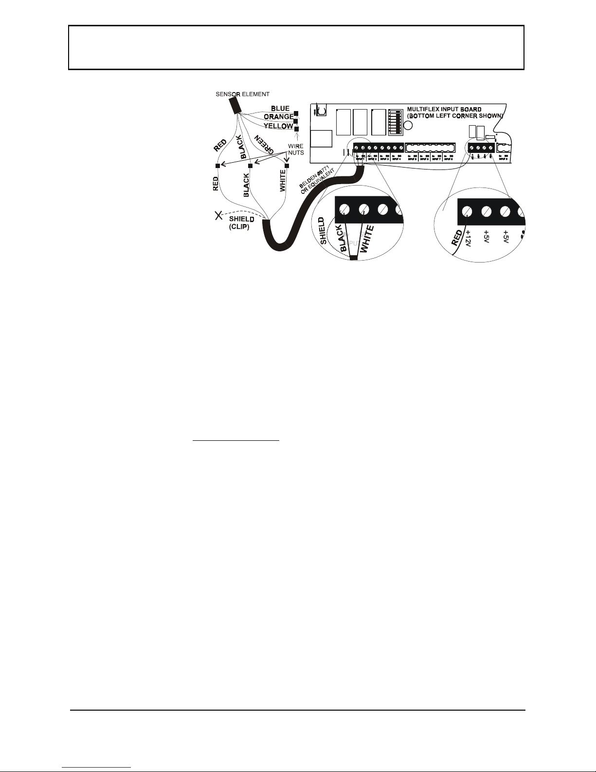
Wiring
NOTE: Do not clip or shorten the
wires leading from the sensor
tube!This will allow enough slack to
remove the sensor element without
having to unmount the enclosure.
1. Use Belden #8771 shielded threeconductor cable or equivalent.
2. Connect the RED, BLACK, and
WHITE wires to the RED,
BLACK, and GREEN wires from
the sensor using the wire nuts
supplied in the kit. Use the
remaining wire nuts to cap and
insulate the unused leads (BLUE,
ORANGE, and YELLOW). Clip
the shield (BARE) wire.
3. On the input board, connect the SHIELD and BLACK wires to the 0V terminal. Connect the WHITE wire to the SIG terminal
of the input board.
Figure 2 - Sensor and Input Board Wiring
4. Connect the RED wire to the +12V power terminal on the input board.
5. Locate the input dip switch for the sensor point, and set to the OFF position (LEFT for MultiFlex, DOWN for 16AI). Refer to
the input board’s user manual for locations of the input dip switches.
Finishing the Installation
Once the duct sensor is mounted and the sensor and board wiring is complete, check the gland nut that
secures the sensor tube and tighten it if necessary (see Figure 1 for the location of the gland nut). Attach
the cover plate (with the foam gasket included) to the sensor enclosure using the screws provided. Tighten
all conduit connections, and cap all unused holes
in the sensor enclosure.
Calibration and Replacement
The sensing element of the 203-5771 duct-mount RH sensor is pre-calibrated and will require no physical
adjustment. If the sensor drifts over time, the sensor can be ‘recalibrated’ by replacing the pluggable sensing element. Contact CPC to order replacement elements (P/N 203-5795).
To replace a sensor element, pull the sensor’s power connection from the input board. Remove the
cover plate of the enclosure, loosen the gland nut, and slide the sensor tube out through the enclosure until
the sensor element is completely out of the duct and the tip of the tube can be accessed. Unscrew the top of
the sensor tube to expose the pluggable RH sensor element.
Note the orientation of the sensor element before unplugging it and plug the new sensor element in
using the same orientation. Replace the top when finished, reinsert the tube into the duct, tighten the gland
nut, and restore power to the sensor. There is no other calibration method needed, and no adjustments are
present in the unit.
Note: Do not expose sensor element to the fumes of curing RTV silicone rubber. Doing so
will damage the calibration of the element.
COMPUTER PROCESS CONTROLS - http://www.cpcus.com/ Page 2
 Loading...